
Abstract
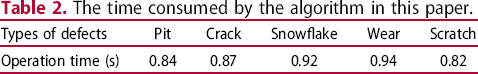
In order to improve the detection efficiency and image quality of Si3N4 ceramic bearing balls surface defects, digital image processing technology is used to analyse the information characteristics of Si3N4 ceramic bearing balls surface. A multi-scale decomposition enhancement algorithm for surface defect images of Si3N4 ceramic bearing balls based on the stationary wavelet transform is proposed. By building the surface defects detection system of Si3N4 ceramic bearing balls, the image enhancement program based on stationary wavelet transform with index low-pass filtering and nonlinear transform enhancement is designed. Finally, the effectiveness of the algorithm is verified by experiments. The experimental results show that the algorithm is applied to the surface defects image of Si3N4 ceramic bearing balls can effectively weaken the background noise and surface grinding texture, and enhance the contrast between defects and background clearly. In addition, the binary image is obtained by an adaptive threshold binary algorithm. After removing the tiny points by morphological opening operation, the defects are accurately and completely segmented, and then the Canny operator is used for edge detection to extract the edge contour of defects. When the decomposition level is set to 3, the average calculation time is 0.88 s, which are relatively short and have sufficient precision, and the algorithm can be extended to other kinds of ceramic ball surface damage detection.
Introduction
Si3N4 ceramic bearings are commonly used in optical precision instruments, high-speed machine tools, aeroengines, armoured machinery and other fields because of their excellent properties such as wear resistance, corrosion resistance, oxidation resistance, low specific gravity and high strength [1-4]. Si3N4 ceramics are almost not afraid of corrosion, so Si3N4 ceramic bearings can work under harsh conditions covered with corrosive media [57]. The density of ceramic balls is lower than that of the steel balls and its weight is much lighter [8]. Therefore, the centrifugal effect of Si3N4 ceramic bearing on the outer ring can be reduced by nearly 40% when it works, thus prolonging its service life [9]. However, Si3N4 ceramic bearing balls still have some problems, such as brittleness, low impact resistance, fragility and so on [10,11]. Therefore, in the process of use, due to the influence of bearing working environment, human interference and other factors, the surface defects of Si3N4 ceramic bearing balls will inevitably appear. These defects will seriously affect the service life and performance of Si3N4 ceramic bearings [1215]. As a result, it is very important to identify the surface defects of Si3N4 ceramic bearing balls and take measures to eliminate them.
Digital image processing technology has the advantages of non-contact, high flexibility and easy to observe results [16-18]. It is widely used in various non-destructive testing, such as cracks, corrosion and scratch defects on metal surface, bonding quality defects between interfaces, etc. [19,20]. Image enhancement is a dependent on digital image processing. Its purpose is to enhance, weaken or remove some information in the image according to specific requirements, so that the original image can be more suitable for observation and analysis [21,22]. In order to recognise the target clearly from the defects target and enhance the contrast between the target area and the background, many experts and scholars have done a lot of research. Hanzaei et al. [23] used RIMLV operators to detect defects edge in defects detection, and adopted closed morphology operator to fill and smooth the detection area. High precision and efficient automatic image processing systems were proposed. Zhang et al. [24], based on the specular reflection characteristics of ceramic balls, adopted a stripe flat screen designed with anti-precision ray tracing method, and proposed a surface defect detection method based on stripe reflection. Stripe distortion will appear in the defective area of the ceramic ball, and processing through a specific algorithm proves the feasibility of the method. Liu et al. [25] used an infrared thermal imager to obtain the image, within the framework of stationary wavelet transform, applied Fourier transform to carry out exponential low-pass filtering on the approximation coefficient. Then nonlinear transformation was used to process the image to improve the contrast of the solid rocket motor debonding defect image. Zhao et al. [26], in order to improve the contrast between the weak and the small target area and the background in infrared remote monitoring, proposed a fast image enhancement method based on a multi-scale decomposition of salient feature extraction. This method gets a good robustness and effectiveness for infrared image enhancement. Although the above scholars use different enhancement algorithms to detect the target, most of them are not designed for the surface analysis of ceramic bearing ball. The surface of Si3N4 ceramic bearing balls is spherical. The biggest difference between spherical imaging and planar imaging is that spherical imaging has a certain radian. Therefore, in the imaging process, the defect area is not a plane. If the image is directly imaged, the defect and the surrounding background will produce deviation. Therefore, the above-mentioned enhancement algorithm is difficult to achieve a satisfactory enhancement effect. Yang et al. [27] proposed a ceramic ball defect detection system based on machine vision, using high heat filter and median filter algorithm to preprocess, and using the region growth algorithm to extract the defect area. However, due to the limitation of the depth of field of the microscope, the detection system is only suitable for ceramic balls with a diameter of more than 10 mm, and the single effective detection area is small. The detection algorithm is only suitable for extracting the defect areas with obvious differences in grey level, so there is the possibility of missing detection.
In order to enhance the detection efficiency and image quality of Si3N4 ceramic bearing balls surface defects, the information characteristics of Si3N4 ceramic bearing balls surface were analysed by using digital image processing technology. A multi-scale decomposition and enhancement algorithm of Si3N4 ceramic bearing balls surface defect images based on stationary wavelet transform was proposed. This enhancement algorithm has good adaptability to planar and spherical imaging. Stationary wavelet transform (SWT) adopts multi-scale decomposition method, which does not need any upper and lower sampling process, and does not reduce the SWT datum after transformation, which can help us to retain more information [28,29]. Therefore, the image of Si3N4 ceramic ball surface defect is processed by using SWT, and the corresponding coefficients of different scale regions are filtered by index low-pass filter. After the multi-scale decomposition of the image, the target can be extracted more easily and better image enhancement effect can be obtained.
The rest of the paper is structured as follows. The second section introduces the construction of Si3N4 ceramic bearing balls surface defects detection system. The third section analyses the image information characteristics of Si3N4 ceramic bearing balls samples and their surface defects. In the fourth section, the stationary wavelet transform algorithm is presented, and the image multi-scale decomposition and enhancement algorithms are designed. The fifth section analyses image enhancement results of Si3N4 ceramic bearing balls surface defects image, and verifies the reliability of the image enhancement algorithm. Finally, the conclusion is brought in the sixth section.
The construction of Si3N4 ceramic bearing balls surface defects detection system
Preparation of Si3N4 ceramic bearing balls
The technological process of preparing Si3N4 ceramic bearing balls mainly includes the preparation of Si3N4 powder, ball billet forming, ball billet sintering and ceramic ball finishing. First, silicon powder is directly nitride into Si3N4 powder by chemical method (chemical equation:
Preparation process of Si3N4 ceramic bearing balls.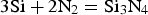 ), and then sintering and forming aid are added. Then, the powder is pressed into 10 mm spherical billets with a certain strength and density. Then, Si3N4 ceramic bearing balls are sintered by hot isostatic pressing machine (HIP200, Beijing disao instrument Co., Ltd.) to form Si3N4 ceramic bearing balls. At this time, the surface of Si3N4 ceramic bearing balls is still relatively rough with a small amount of burr after sintering. The surface of rough Si3N4 ceramic bearing balls is finely ground with a disc vibration grinder (F-VD600, Hunan fucas experimental instrument Co., Ltd.), so as to obtain the precise Si3N4 ceramic bearing balls. The preparation process of Si3N4 ceramic bearing balls is shown in Figure 1.
Construction of Si3N4 ceramic bearing balls surface defects detection system
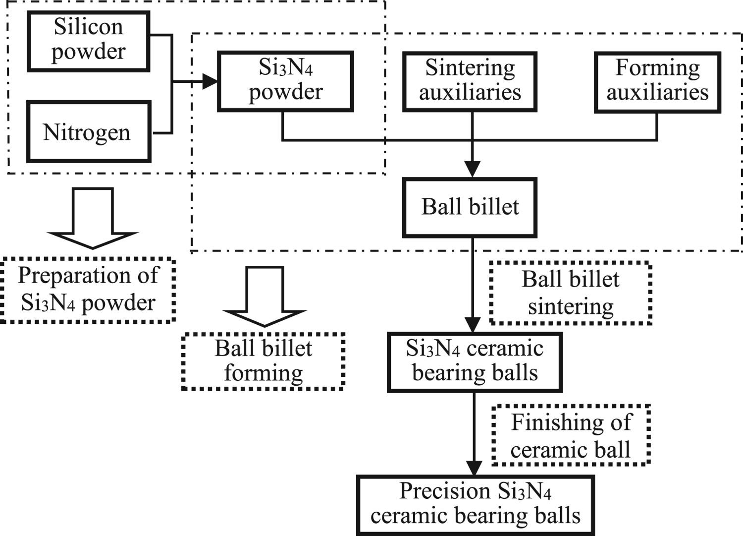
In order to detect the surface defects of Si3N4 ceramic bearing balls, the surface damage detection system of Si3N4 ceramic bearing balls was established. The system is mainly composed of computer, stereo microscope, CCD camera, image acquisition card, loading platform, fluorescent lamp, etc. The structure of the image data acquisition system is shown in Figure 2. The biggest difference between spherical imaging and planar imaging is that spherical imaging has a certain radian. Therefore, in the process of imaging, the defect area is not a plane. If the image is taken directly, the defect will deviate greatly from the surrounding background. First, a microscope (RICOH FL-YFL3528, China daheng (Group) Co., Ltd.) was used to aim at the surface of Si3N4 ceramic bearing balls to be detected, and then the image surface of the ceramic bearing balls is magnified. Then, the image of the enlarged ceramic ball surface was imaged by a CCD camera (MER2-2000-6Gx, China daheng (Group) Co., Ltd.). The control console is controlled by a computer to make the ceramic ball rotate anticlockwise, so that the camera can take pictures of the entire surface of the ceramic ball. At this time, the spherical defect is transformed into the plane defect type for analysis. After that, collected image data are input into the computer. The digital image is processed by using the multi-scale decomposition and enhancement algorithm of Si3N4 ceramic bearing balls surface defects image based on SWT.
Structure of image data acquisition system.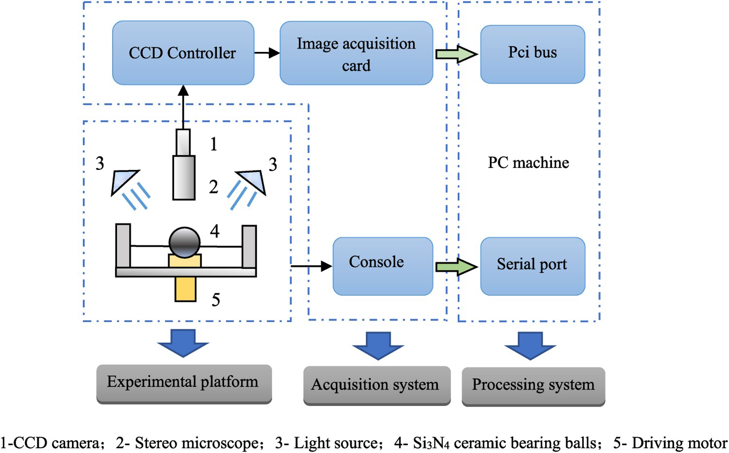
Surface defect image characteristic analysis of Si3N4 ceramic bearing ball
The experimental specimen
The actual specimen and size of Si3N4 ceramic bearing balls are shown in Figure 3. The test specimen is black and grey, with a diameter of 10 mm. After working, the surface of Si3N4 ceramic bearing balls has become significantly rougher, resulting in defects that can be observed or not by the naked eye.
Physical object and size of Si3N4 ceramic bearing balls test specimen.
By observing the surface of Si3N4 ceramic bearing balls, the defects can be divided into five categories: pit, crack, snowflake, wear and scratch. The pit defects showed local tissue peeling, the crack defects showed annular or linear ring and linear shape, the snowflake defects showed large area of netted white spot or pitting, the wear defects is banded and there is no obvious depression, and the scratch defects showed linear and the trace is relatively shallow. In the process of collecting the surface defects image of Si3N4 ceramic bearing balls, the cleaning degree of ceramic ball surface, the error of the image acquisition system and the surrounding environment will greatly affect the subsequent image processing process. It can be found that in the image, the contrast between the defects area and the normal area is low, and the noise in the image is high, which makes the defects recognition difficult. Therefore, it is very important to enhance the surface defects image of Si3N4 ceramic bearing balls. Take scratch defects as an example. The 2D and 3D images of the scratch defects on the surface of Si3N4 ceramic bearing balls are shown in Figure 4.
Scratch defects image of Si3N4 ceramic bearing balls.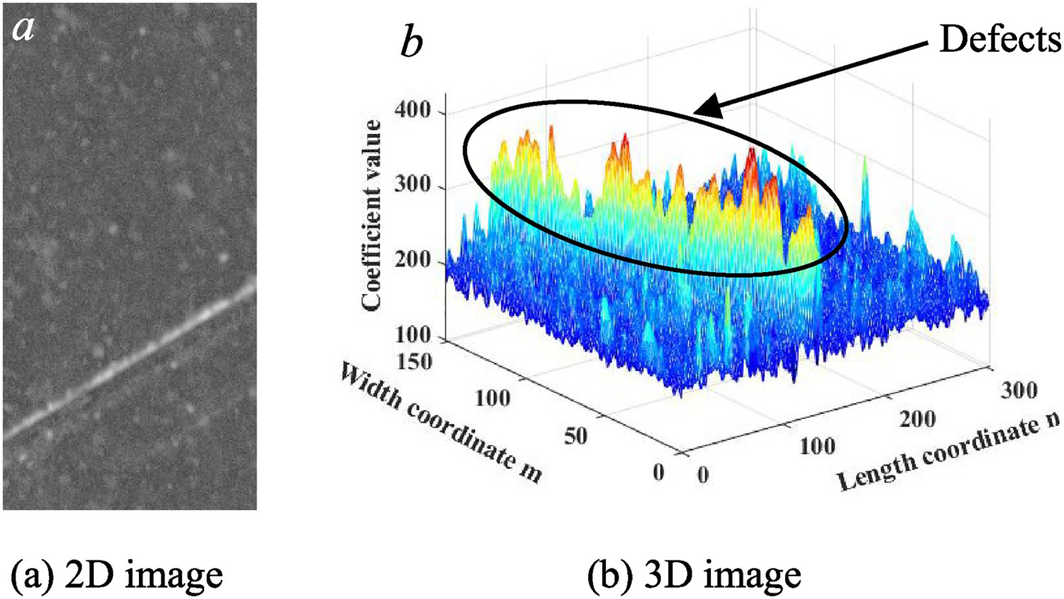
Information properties of Si3N4 ceramic bearing balls surface defects image
The surface image signal of Si3N4 ceramic bearing balls generally includes defects signal, background signal and noise signal. Both defects signal and background signal are in the low frequency subband of frequency domain or wavelet domain. In the defective image of Si3N4 ceramic bearing balls, the grey value of the defects area is higher than that of the normal area. The grey value of defects area corresponds to a defects signal, while that of normal area corresponds to the background signal. The grey level of the two kinds of signals changes slowly in the image, so the signal can be retained after index low-pass filtering. The noise signal is located in the high frequency sub-band of the frequency domain or the wavelet domain, which is not conducive to defects identification. In the image shown in Figure 4(a), there are a large number of noise points, which are all from the noise. The threshold segmentation method is adopted to remove these noise. In the defects area, some may be mistaken for the normal area, which can be eliminated in the frequency domain or the wavelet domain through index low-pass filter.
Design of image multi-scale decomposition enhancement algorithm
Analysis of stationary SWT
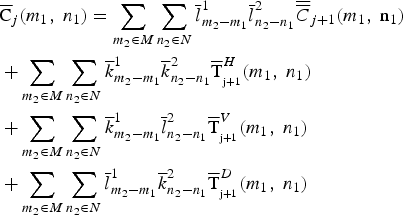
SWT is a type of wavelet transform method based on orthogonal wavelet transform. It can overcome the shortcomings of orthogonal wavelet transform on image, achieve the beneficial effect of removing dryness, and deal with details better. This is likewise the reason for using SWT. The realisation of discrete wavelet transforms mainly includes Mallat algorithm and á trous algorithm. Mallat algorithm will cause large change of wavelet transforms coefficient when the input signal has a small displacement. That is, it has no displacement invariance. Therefore, in order to overcome this shift invariant feature, the á trous algorithm is used for the stationary wavelet transform. Given the size of an image as M*N, the approximation coefficient Cj(m1,n1) is decomposed into four components: the approximation coefficient Cj +
1(m1,n1) with the scale of j +
1 and the wavelet coefficient Tj +
1(m1,n1). The wavelet coefficients are further divided into horizontal wavelet coefficients
 , vertical wavelet coefficients
 and diagonal wavelet coefficients
 .
.
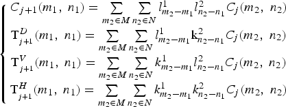
 ,
,
 are low-pass filters;
 ,
,
 are high-pass filters.
The coefficient decomposition process of á trous algorithm is shown in Figure 5. The á trous algorithm does not need the down extraction and sampling process, which retain more details in the approximation coefficient and has displacement invariance, which is conducive to achieving the ideal effect of subsequent image enhancement.
Coefficient decomposition process of á trous algorithm.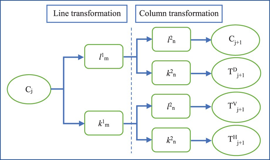
Design of image enhancement algorithm
The method of image enhancement is to add some information or transform data to the original image by a series of technical means, transform the image into a form more suitable for human or machine analysis and processing, selectively highlight the features of interest in the image or suppress some unnecessary features in the image, so as to match the image with the visual response characteristics. Image enhancement can be divided into two categories: frequency domain method and spatial domain method. The former regards the image as a 2D signal and enhances it based on the 2D Fourier transform. The low-pass filtering method can remove the noise in the defects image; the latter directly processes each pixel of the image, which can be divided into point operation and local operation, which can be used to remove or weaken the noise. In this paper, an image enhancement program based on index low-pass filtering and nonlinear transformation enhancement based on SWT is designed. The design process is shown in Figure 6.
The design flow of image enhancement program.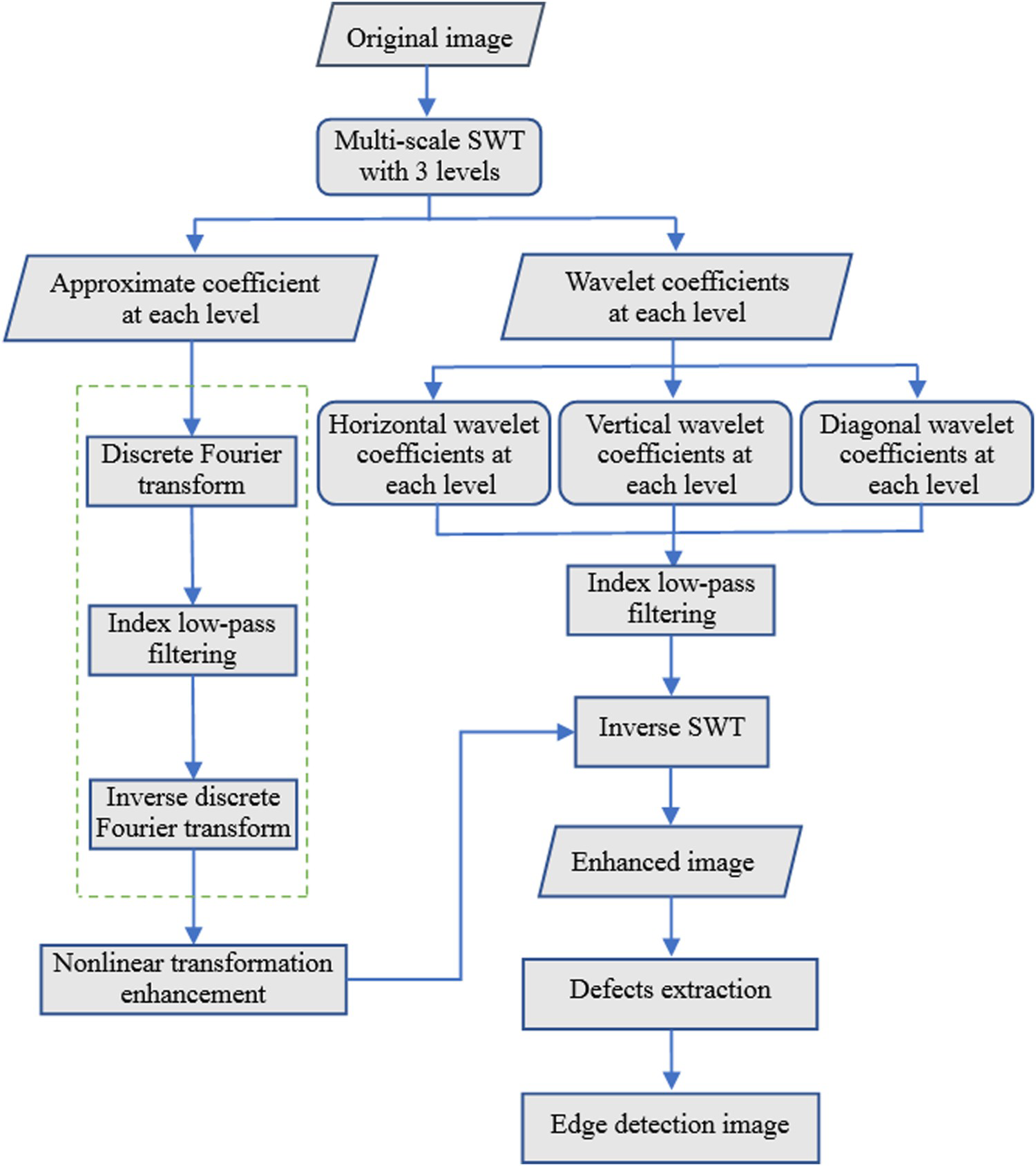
According to the design process of image enhancement program, the image processing process is described as follows:
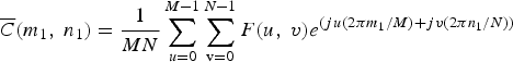
In order to achieve a balance between detection accuracy and computational complexity, the fourth-order Daubechies wavelet transform (db4) is used to decompose the surface defects image of Si3N4 ceramic bearing balls into four levels, and the approximate coefficients of the fourth level and the wavelet coefficients at each level are obtained. The appropriate approximation coefficient can retain the defects image information to a large extent, and the image noise is small. The wavelet coefficients and noise are between the high frequency subbands, and most of the wavelet coefficients in each layer are noise. Therefore, the horizontal wavelet coefficients, vertical wavelet coefficients and diagonal wavelet coefficients are set to 0, so as to eliminate the noise to the greatest extent. In order to further eliminate noise interference, the fourth-level approximate coefficients C(m1,n1)are transformed from the space domain to the frequency domain by Fourier transform. The mathematical formula of the Fourier transform is:
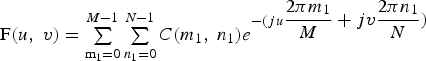 (2)where (u,v) is the point coordinates in the frequency domain; F(u,v) is the Fourier transform value.Then, the index low-pass filtering is carried out in the frequency domain, and the formula is as follows:
 (3)
(3)
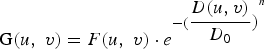
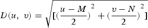 (4)where G(u,v) is the modified Fourier spectrum; D(u,v) is the distance from the point (u,v) to the centre of Fourier transform; n is the order; and D0 is the cut-off frequency.
Finally, the modified Fourier spectrum G(u,v) is used to calculate the inverse Fourier transform, and the approximate coefficients
 are obtained, by using the following equation:
 (3)In order to segment the surface defects in the reconstructed Si3N4 ceramic bearing balls image better, it is necessary to further improve the contrast between the defects region and the background region. Use nonlinear transformation enhancement method to further process the approximate coefficient
 after index low-pass filtering, which can be expressed as:
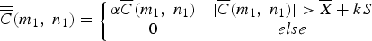 (6) where
 is the approximate coefficient after enhancement processing; α is the enhancement coefficient of defects signal, with the value range of [0,+∞];
 is the average value of the approximate coefficient; S is the standard deviation of approximate coefficient; k is the scope of enhancement, with the value range of [0,+∞].(4) Through the obtained
 and horizontal, vertical and diagonal wavelet coefficients, the synthesised image is obtained by inverse stationary wavelet transform, by using the following equation:
 (7)where
 ,
,
 are low-pass filter reconsecrated;
 ,
,
 are high-pass filter reconsecrated;
 ,
,
 ,
,
 are the horizontal, vertical, and diagonal wavelet coefficients at various levels, respectively.
The experimental results and discussion
In the surface defects of Si3N4 ceramic bearing balls, the scratch defects are representative. Therefore, this paper will illustrate the enhancement process of scratch defects image. Treatment results of other defects types will be described in the last part.
The multi-scale decomposition of defects images
The multi-scale decomposition of Si3N4 ceramic bearing balls scratch defects image is divided into 1–3 levels. After many experiments, when the decomposition level is 3, the defects image enhancement effect can be achieved. The decomposition coefficient of the three levels is shown in Figure 7. The horizontal, vertical and diagonal wavelet coefficients contain different degrees of the defects information, and the value of the defects region is higher than that of the normal region. Therefore, the horizontal, vertical and diagonal wavelet coefficients of each layer are processed by index low-pass filtering.
Comparison of three levels wavelet coefficients.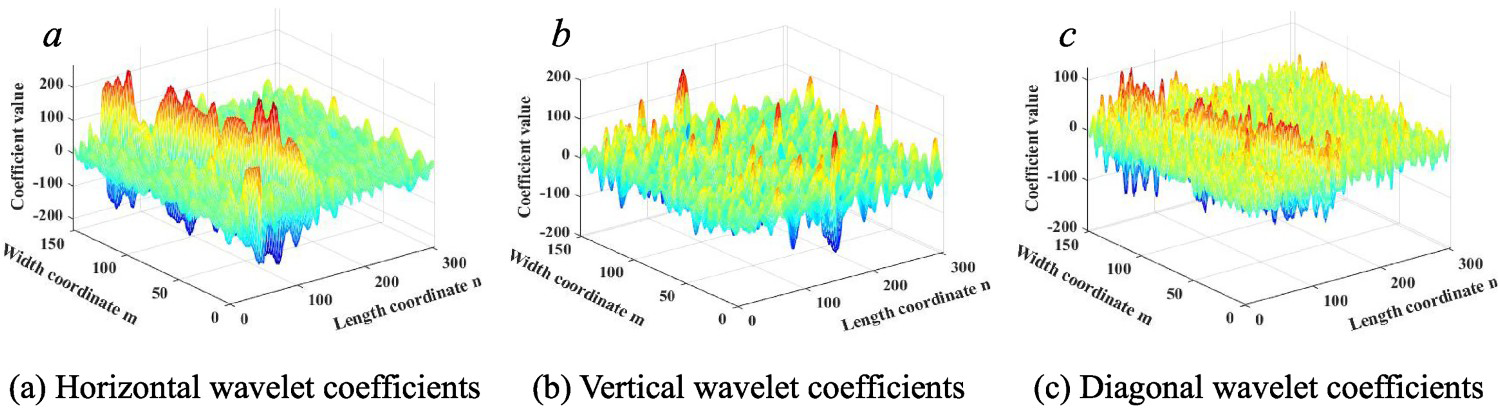
The maximum and minimum values of approximate coefficients of three-level decomposition.
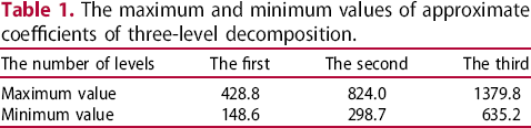
Figure 8 shows the 3D diagram of the approximate coefficient of each layer. It can be observed from the figure, the noise is reduced in Figure 8(b) compared with Figure 8(a). In Figure 8(c), the noise is further reduced compared with Figure 8(b). With the multi-scale decomposition step by step, the noise on the approximate coefficients will be less and less. After three-level decomposition, the noise is obviously decreased, which is conducive to the next enhancement process.
3D diagram of approximate coefficients of each level.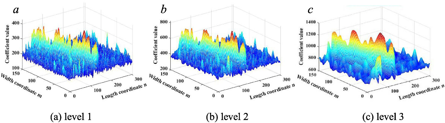
Defects image enhancement process
Index low pass filtering
An index low-pass filter based on Fourier transform is used to process the third order approximation coefficients in Figure 8(c). Set the cut-off frequency D0 = 60 Hz and exponent n = 3. The 2D Fourier spectrum before and after index low-pass filtering and the image after Fourier transform are shown in Figure 9. As shown in the figure, the 2D Fourier spectrum after logarithmic transformation is brighter near the origin and darker away from the origin, i.e. more low-frequency components and less high-frequency components.
2D Fourier spectrum before and after index low-pass filtering.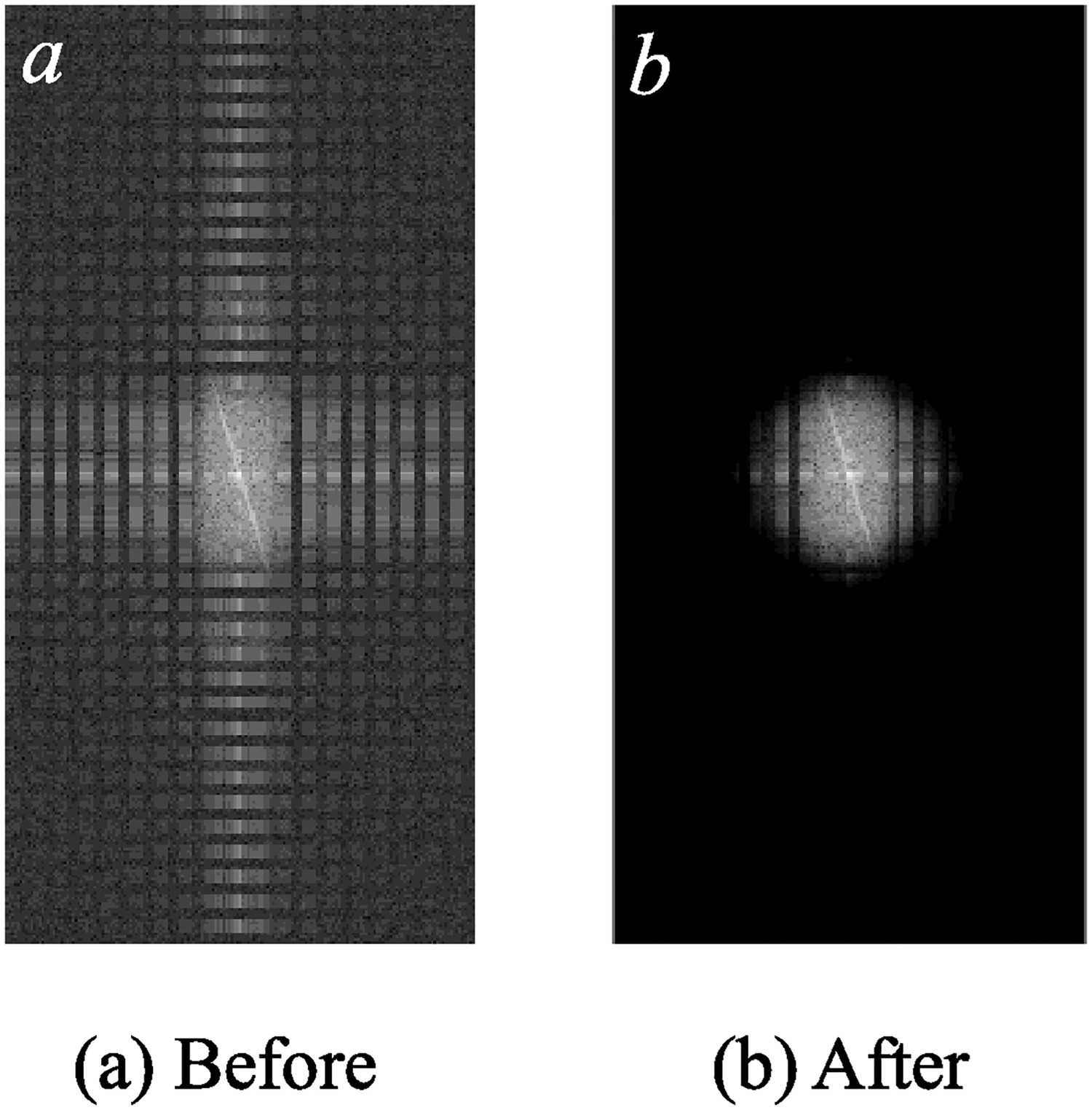
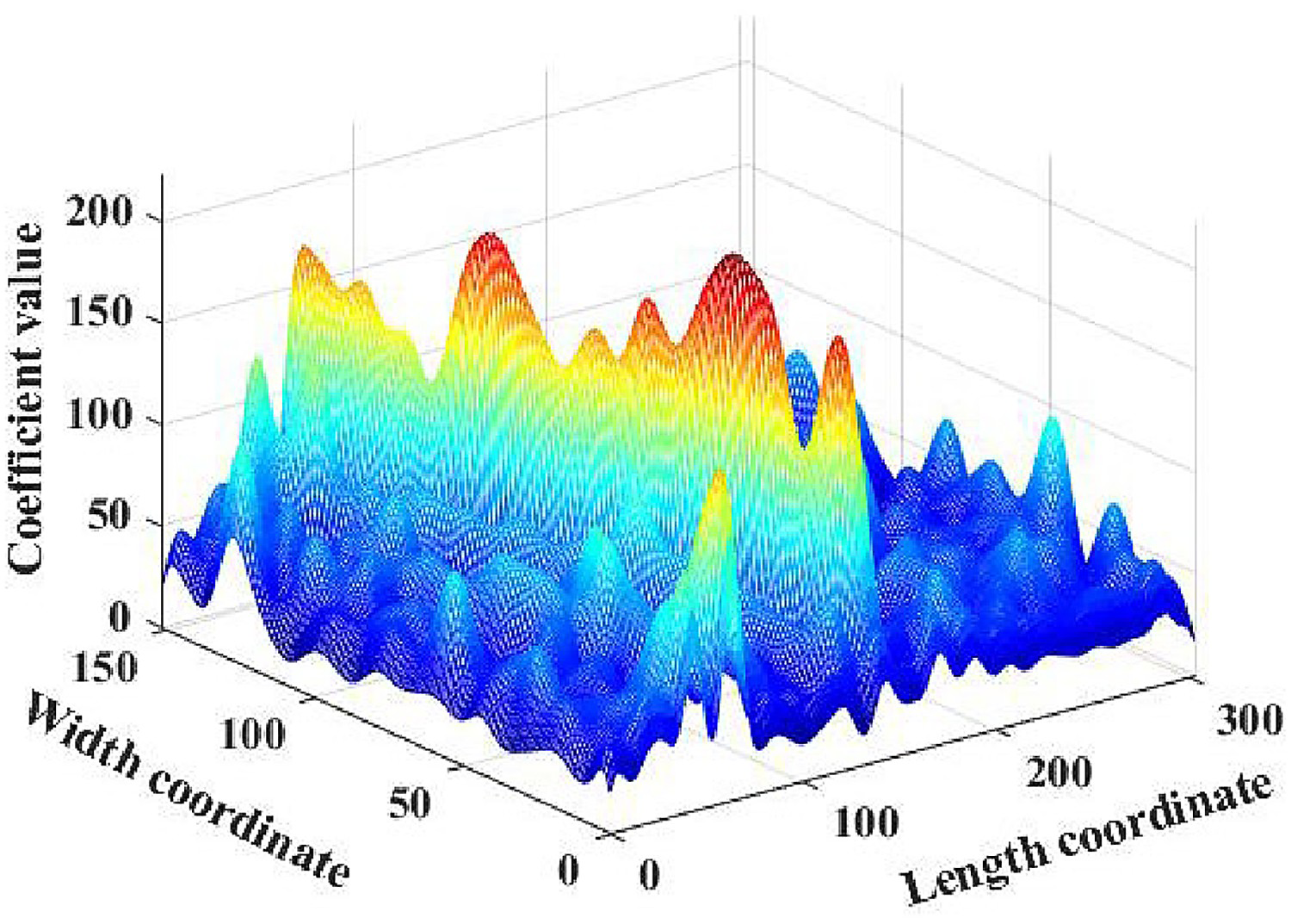
Because the defects area signal is located in the low-frequency component, the high-frequency component will be eliminated after exponential low-pass filtering, and the defects information can be well preserved. The 3D image after exponential low-pass filtering is shown in Figure 10. At this point, the scratch defects have been clearly shown in the 3D image.
(2) Nonlinear transformation enhancement 3D image after index low-pass filtering.
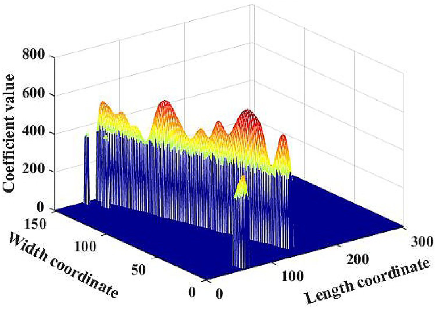
Then, the defects image after exponential low-pass filtering is enhanced by nonlinear transformation with formula 6. Set the coefficient α = 3, k = 3. The 3D image after non-linear transformation enhancement is shown in Figure 11. After the non-linear transformation enhancement processing, the defective area of the image is well preserved, the noise signal and background signal are eliminated, and the contrast between the defects area and the normal area is enhanced.
(3) Defects image reconstruction 3D image after non-linear transformation enhancement.
Finally, based on the approximate coefficient of three-level decomposition and the horizontal, vertical, diagonal wavelet coefficients at each level. The inverse SWT is used to obtain the reconstructed image of the noiseless signal and background signal. The final enhanced image is shown in Figure 12. The 2D and 3D images in the figure can clearly and accurately show the scratch defects. The defects area in Figure 12(b) contrasts strongly with the surrounding area, highlighting the scratch defects.
The final enhanced image of damage defects is obtained.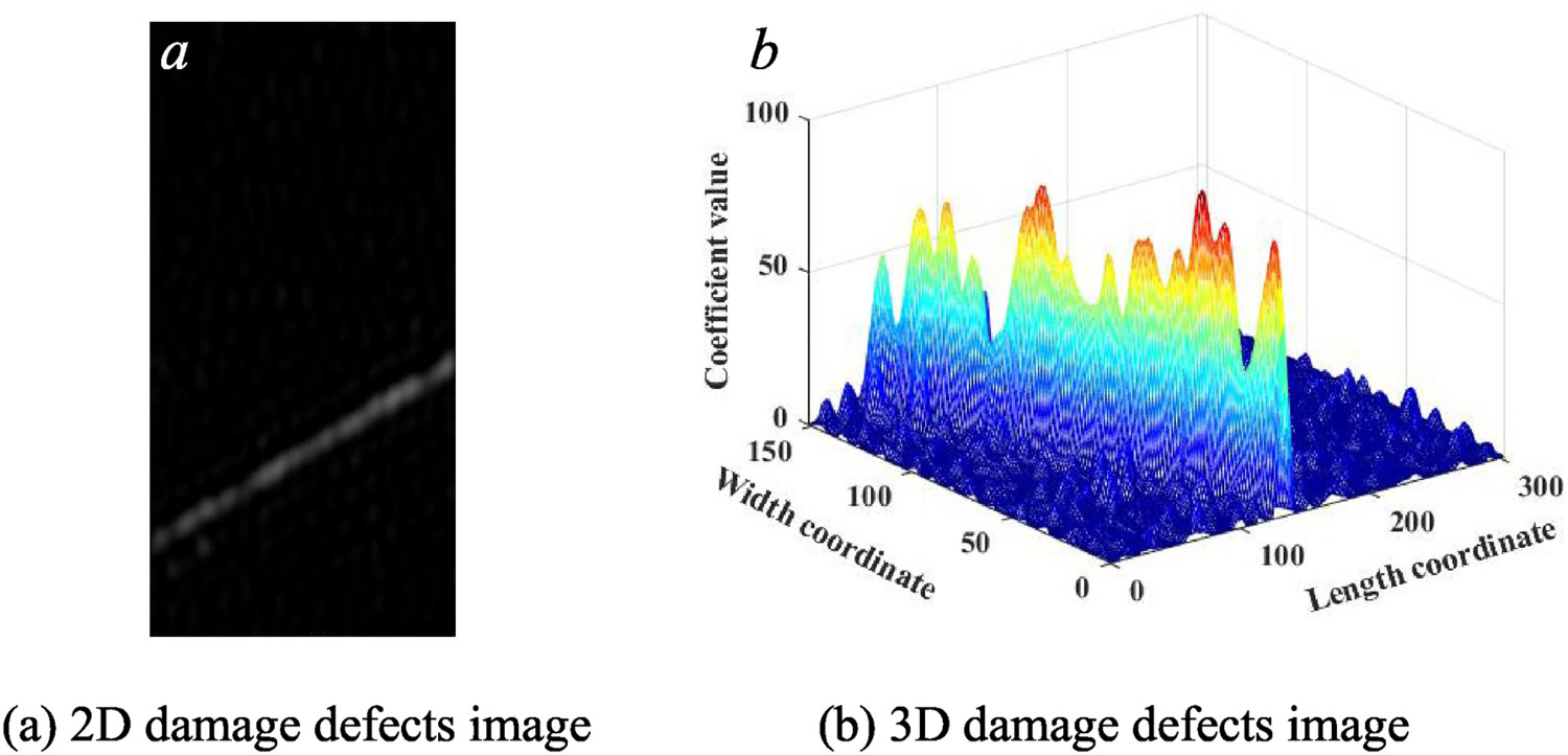
Defects binary image and defects extraction
In order to show the scratch defects area more clearly, the adaptive threshold binarisation algorithm is used to obtain the binary image. Then, by using the morphological open operation, the structural element is set to 2, the small points are removed, and the final binary image of scratch defect is obtained. The scratch defects area accounts for 9.23% of the whole image area. At this time, the small points in the image have been removed, and there is almost no noise, and the defects are well preserved. Next, in order to extract the defects, Canny operator is used to detect the edge of the scratch defects. The scratch defects binary image and defects extraction process are shown in Figure 13.
Scratch defects binary image and defects extraction process.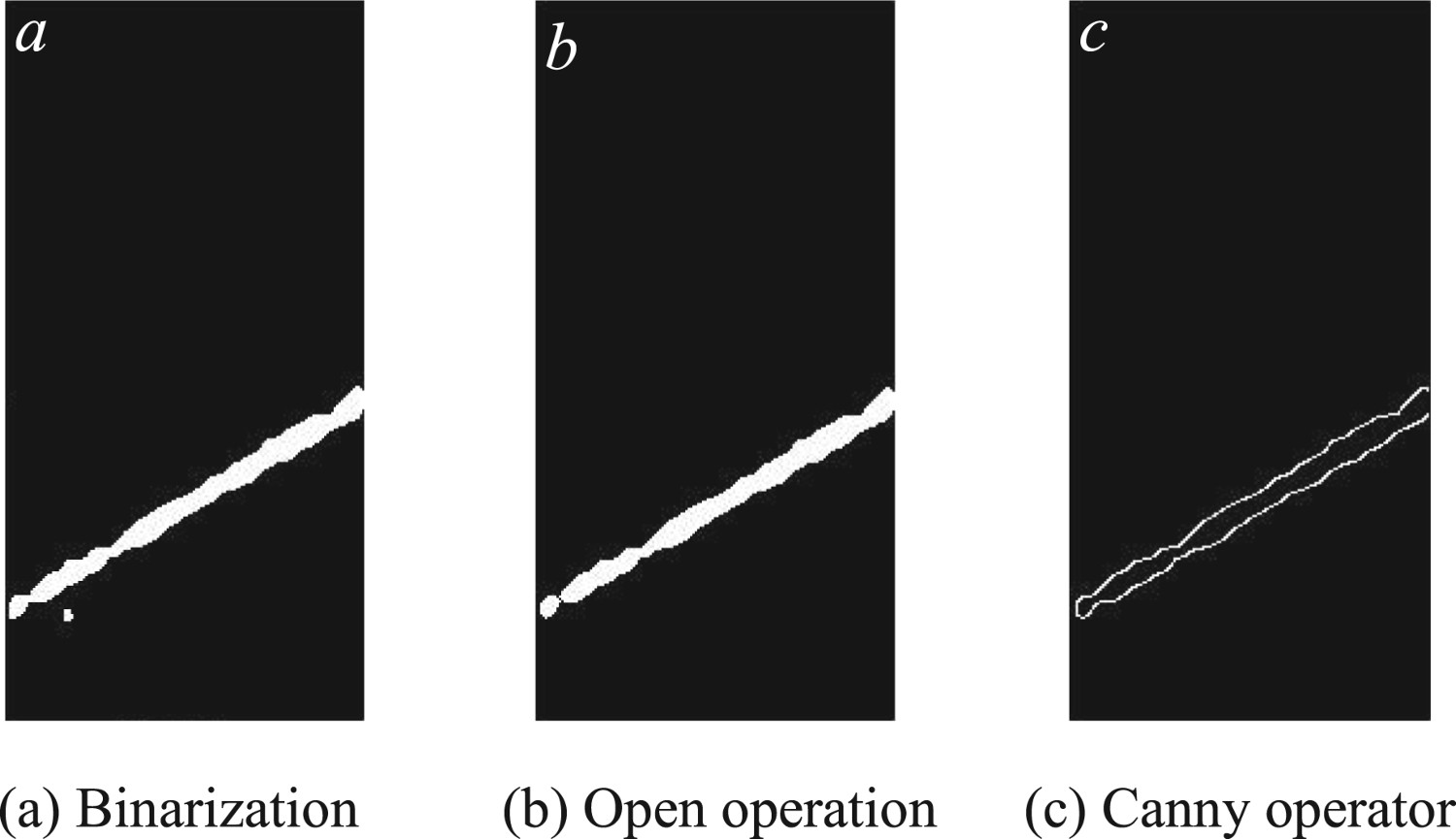
Comparison of defects types
Based on the image enhancement algorithm proposed in this paper, five kinds of defects such as pit, crack, snowflake, wear and scratch are processed for Si3N4 ceramic bearing balls surface defects image. The main processing flow of five types of defects is shown in Figure 14. It can be seen from the figure that the enhanced image (Figure 14(d)) extracted by the enhanced image algorithm proposed in this paper can effectively weaken the background noise and surface grinding texture, and clearly and effectively enhance the contrast between defects and background. Therefore, as shown in Figure 14(f,g), the defects can be accurately and completely segmented and the defects edge contour can be extracted.
2D images of main processing flow of five kinds of defects.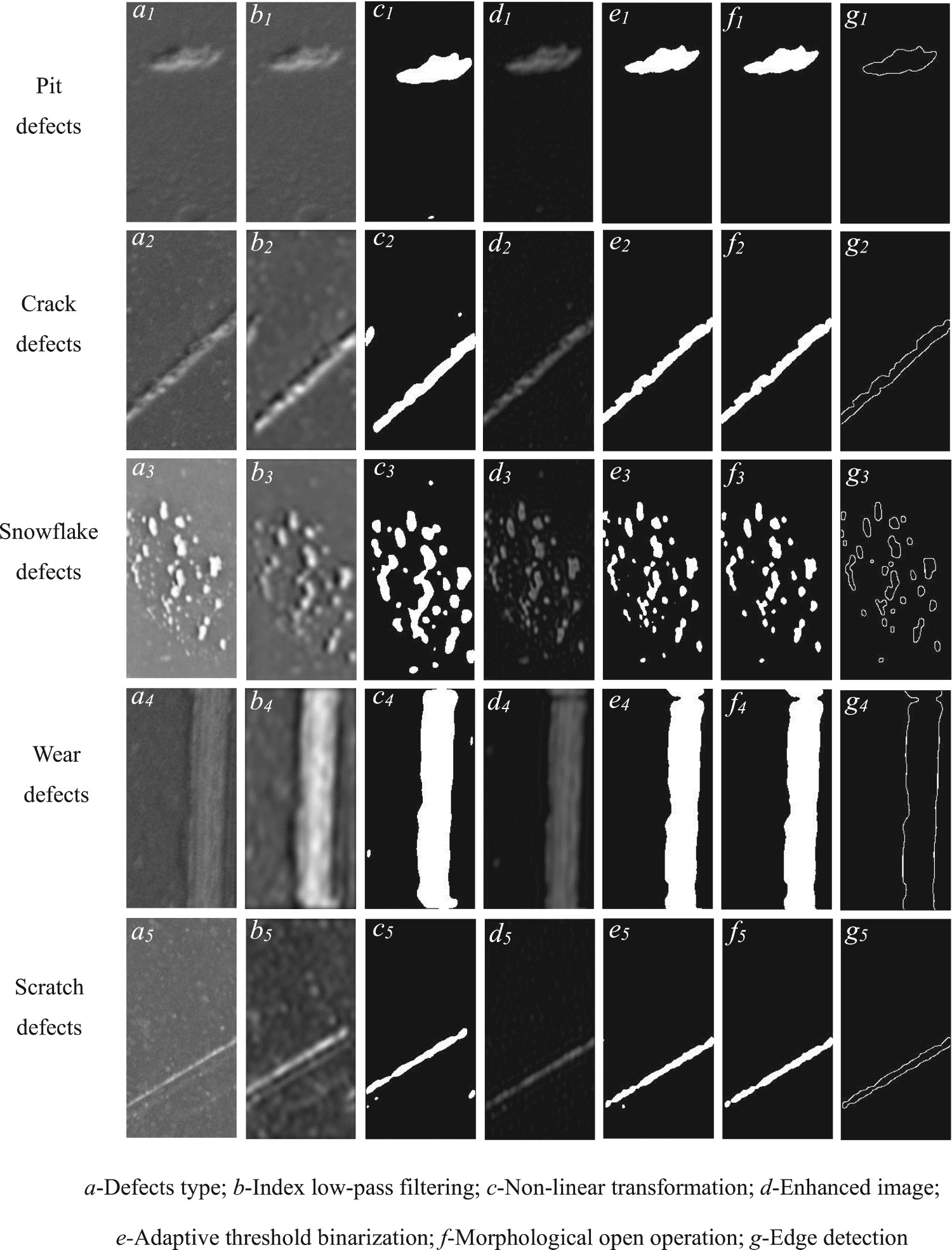
The time consumed by the algorithm in this paper.
Conclusion
In this paper, a multi-scale decomposition enhancement algorithm for surface defects image of Si3N4 ceramic bearing balls based on the stationary wavelet transform is proposed. According to the image characteristics of Si3N4 ceramic ball surface defects, the detection system of Si3N4 ceramic bearing balls surface defects is built, and the image enhancement program based on stationary wavelet transform with index low-pass filtering and nonlinear transform enhancement is designed Finally, the effectiveness of the algorithm is verified by experiments. The experimental results show that the method can effectively weaken the background noise and surface grinding texture, and enhance the contrast between defects and background clearly. In addition, an adaptive threshold binarisation algorithm is used to obtain the binarisation image. The defects are segmented accurately and completely after removing the tiny points by morphological opening operation. Then Canny operator is used to detect the edge of the defects, and the contour of the defects edge is extracted. Although the algorithm is designed to enhance the surface defects image of Si3N4 ceramic bearing balls, the process of weakening background noise and surface grinding texture, enhancing the contrast between defects and background has good generalisation ability for the surface defects image of Si3N4 ceramic bearing balls. And the imaging detection system takes into account the problem of spherical imaging radian, which further improves the detection effect of Si3N4 ceramic bearing ball surface defects. Therefore, it can be extended to other kinds of ceramic ball surface damage detection.
Footnotes
Acknowledgements
This work was supported by National Natural Science Foundation of China (Grant number 51964022).
Disclosure statement
No potential conflict of interest was reported by the author(s).