
Abstract
Boundary slip as well as surface texturing is an effective method to improve the tribological performance of lubricated mechanical components. This article analyzes the combined effect of single texturing (pocketing) and wall slip on pressure that strongly related to the load-carrying capacity of slider bearing. The modified Reynolds equation for lubrication with non-Newtonian power-law fluid is proposed. The equation was solved numerically using a finite difference equation obtained by means of the micro-control volume approach. Further, numerical computations for slider bearing with several power-law indexes were compared with the presence of the pocket and slip. The numerical results showed that the characteristic of non-Newtonian is similar to Newtonian fluid with respect to hydrodynamic pressure distribution. The maximum load support is achieved when the pocket depth is equal to the film thickness.
Introduction
In recent years, bearing have offered significant technological advancement and have played important roles in many significant areas. However, one main factor that limits the widespread development and reliability of bearing is a high level of friction and wear. 1 The use of artificial surface texturing is becoming popular in oil-lubricated devices because of its potential benefits in terms of load support and friction force, both experimentally and theoretically. It was shown experimentally that such texturing enhances the load support and reduces friction force, for instance, systems with two parallel sliding surfaces, 2 and in reciprocating (cylinder-liner) contacts, 3 Recently, in addition to surface texturing, the use of an artificial slip surface was also of great interest with respect to lubrication.4–6 The Newtonian fluid lubricants were used to analyze the lubrication performance in previous researches.
As a consequence of the development of modern machines and the requirement of severe operation conditions, the increasing use of non-Newtonian fluids as lubricants has received much attention. For slider bearings with non-Newtonian fluids investigation, Dien and Elrod 7 developed the regular perturbation technique to extend pressure and velocity into series of forms. It is then substituted into the Navier–Stokes equation to derive a modified Reynolds equation for a power-law fluid model. Buckholz 8 used a power-law model as a non-Newtonian lubricant to analyze load capacity and friction for plane slider bearing. Yürüsoy 9 investigated an infinitely wide lubricated slider bearing consisting of connected surfaces with power-law fluid as lubricant. Dynamic characteristics of slider bearings with finite width have been analyzed by Jaw-Ren Lin et al. 10 . Furthermore, they explored the effects of non-Newtonian couple stresses on Rayleigh step slider bearing lubrications. 11 Many investigators have also introduced an analytical approach for the analysis of slider bearing with non-Newtonian lubricants.12–14 However, all of them still implemented the assumption of the no-slip surface boundary condition.
In order to reflect the more real phenomena, it is necessary to include the boundary slip effect on the non-Newtonian-lubricated contact. This paper is focused on deriving the new lubrication model based on Reynolds theory with a non-Newtonian lubricant. The behaviour of hydrodynamic performances as in pressure is of particular interest. Moreover, various parameters (power-law indexes, pocket height, pocket length, slip zone and slip coefficient) affecting the pressure as well as the load support were examined.
Method
The hydrodynamic thin-film lubrication can be expressed using a mathematical model obtained by the Reynolds theory. This equation is obtained from the simplification of Navier–Stokes momentum equation and the equation of continuity. The elastic deformation of the bearing surface is very small and can be ignored in the hydrodynamic lubrication regime. Further, in this paper, the modified Reynolds equation was applied for lubrication with a non-Newtonian power-law fluid.
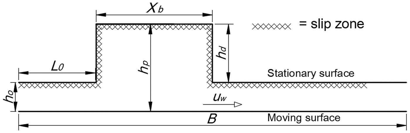
Numerical simulations were used to investigate the hydrodynamic performance of pocketed slider bearing with a boundary slip. The Navier-slip stress criterion was conducted to analyze slip on bearing surface. The flow was assumed to be laminar, isoviscous and isothermal. The schematic of a lubricated slider bearing is presented in Fig. 1. The lower body slides at a constant velocity u
w
, while the upper body is stationary. In this study, a non-Newtonian fluid is modelled by the power-law. It reads:

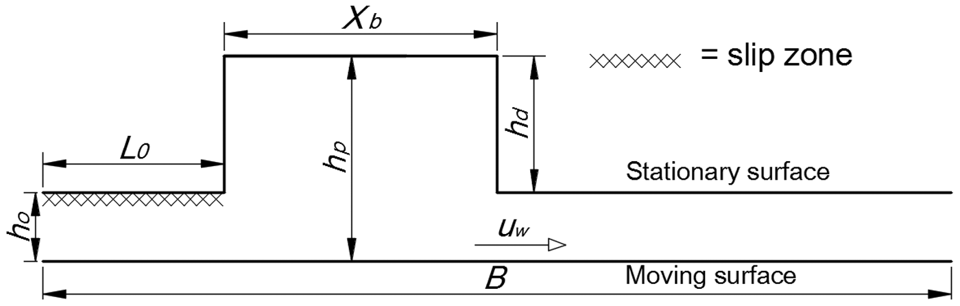
Schematic of a lubricated slider bearing. (Note: h o = inlet film thickness, h p = texture thickness, h d = pocket height, X b = pocket length, u w = moving velocity)
The fluid velocity is expressed as:
With the assumption of Navier slip for modelling the boundary slip, the modified flow rate reads:
The derivation of equation (3) is explained in detail in Appendix 1. It should be noted that equation (3) is the modified Reynolds equation derived for over the whole bearing. The physical meaning of the symbols in equation (3) is as follows: h, the local film thickness; p, the lubrication film pressure; η, the lubricant viscosity; α, slip coefficient; subscript s refers to the moving wall; and subscript h refers to the stationary wall. It can be seen that if the slip coefficient α is set to zero (no-slip condition), equation (3) reduces to the classical Reynolds equation.
The slip coefficient α as well as the slip zone L
s
is of particular interest. The slip coefficient is defined as an extrapolated distance relative to the wall where the tangential velocity component vanishes. The lubricated sliding contact presents the following characteristics:
Film thickness, h = 1 × 10⁻⁶ m. Length of slider bearing, B = 2 × 10⁻³ m. Slip coefficient, α = 0.02 Inlet length, L0 = 0.2 B Power-law index, n = 0.85 Pocket height, h
d
= 2.5 h0 Pocket length, X
b
= 0.3 B
In this study, the modified Reynolds equation is solved numerically using a finite difference equation obtained by means of the micro-control volume approach. 15 The entire computed domain is assumed as a full fluid lubrication. By employing the discretization scheme, the computed domain is divided into number of control volumes. The mesh number for all the situations obtained from a mesh refinement study is 1000 for model validation and 5000 nodes for pocketed slip slider bearing analysis, respectively. For all derivatives, the central difference is used except at the boundaries. Appropriate one-sided difference is used at the boundaries.
Based on equation (3), the hydrodynamic pressure distribution is solved iteratively at each grid point using the alternating direction implicit with the tridiagonal matrix algorithm. 15 Further, the load support can be determined by integrating the calculated hydrodynamic pressure. It should be noted that the following simulation results are obtained with an accuracy of tolerance (Tol) of 10−6.
Results and discussion
Focus of this research consists of two main parts: the validation model and the simulation of pocketed slip slider bearing lubrication with a non-Newtonian fluid. Dien and Elrod work is used as the validation model. In addition, the present numerical computation is compared to their model.
7
The primary parameters are set up as follows: inlet–outlet ratio, h0/h1, is 2, the power-law indexes, n, are 1/3, 1/2 and 1. The comparison results will be presented in dimensionless pressure
 .
.
For investigating the effect of the slip parameters and pocketing characteristics on the lubrication performance of sliding surfaces, various parameters are initially defined. The main parameters of the lubricated sliding contact are given as follows: sliding velocity, u
w
, is 1 m/s (the corresponding Reynolds number, Re, is 1 and the dynamic viscosity, η, is 0.001 Pa.s). In the following simulations, slip coefficient, α
s
, varies from 0 to 0.1 m2 s/kg based on the other published works.
16
The power-law indexes, n, are 0.7, 0.85 and 1 for investigating the effect of power-law indexes. The pocket height, h
d
, varies from 0.5 h0 to 7.5 h0 for searching the optimum value. The pocket length, X
b
, are simulated from X
b
= 0.1 B to X
b
= 0.7 B. To enhance the optimum slip zones, L
s
, its value varies from 0.2 B to 0.85 B. Further, the results were compared to the other published works.5, 6 The results of simulation will be presented in dimensionless form, i.e. for dimensionless pressure and
 for dimensionless load support. It should be pointed that in this present investigation, the dimensionless load support, w+, as well as dimensionless pressure, p+, is proportional to η′ u
w
.
for dimensionless load support. It should be pointed that in this present investigation, the dimensionless load support, w+, as well as dimensionless pressure, p+, is proportional to η′ u
w
.
Validations
In order to validate the model, the numerical code is developed. A comparison between this result and other published works has been performed. Fig. 2 shows the comparison of the dimensionless pressure distributions to various power-law indexes of pseudoplastic for classical (no-slip) bearing. For the validation of the present numerical computation, the results were compared to the exact solution proposed by Dien & Elrod 7 . It can be seen in Fig. 2, the simulation results match well to the theoretical prediction, 7 especially with n = 1. In the case of non-Newtonian fluid with n = 1/3, n = 1/2, the deviation is relatively small (<3%). Therefore, the numerical algorithm can be extended for analyzing the pocketed bearing with boundary slip.

Pressure distribution for infinite width slider with various pseudoplastics (h0/h1 = 2, n = 1/3, 1/2 and 1). (Note:
and x+ = L
x
/B)
The effect of power-law indexes
The power-law index, n, showing the level of non-Newtonian fluid is also investigated in this paper. Fig. 3 shows the comparison of the dimensionless pressure distributions with various power-law indexes of pseudoplastic for pocketed slider bearing with boundary slip. As reflected in Fig. 3, the peak of dimensionless pressure distribution reaches the highest value in the highest power-law index. Consequently, the bearing will have the highest load support. For Newtonian fluid (when n = 1), the generated load support has the highest value. It can be noted that when n = 0.85, the pressure is not significantly different to the result with n = 1. On the other hand, when n = 0.7, the pressure drop is significant. This is as expected because in non-Newtonian analysis (
 ,
,
 ), the pressure is dependent on the n value exponentially.

Pressure distribution for pocketed slider bearing with various pseudoplastics (n = 0.7, 0.85 and 1).
The effect of pocket height
A comparison between the dimensionless pressure distributions and various pocket heights is presented in Fig. 4. The peak of dimensionless pressure distribution is the highest for the pocket height h d equal to film thickness h0. This indicates that the finding is similar to the Newtonian-lubricated bearing with slip. It was stated that for Newtonian fluid, the highest load support is achieved when the contact is flat (no pocket), while the slip zone is introduced at the leading edge of the contact.5, 6
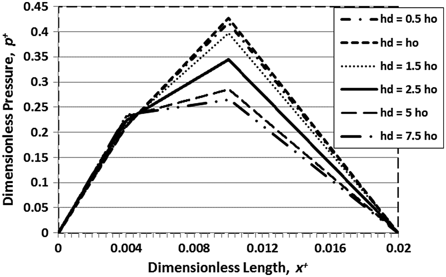
Pressure distribution for pocketed slider bearing with various pocket heights (h d = 0.5 h o , h o , 2.5h o , 5h o and 7.5h o ).
The effect of pocket length
Fig. 5 shows that the pressure distributions increase from X
b
= 0.1 to 0.5. After 0.5, the graph trend tends to decrease gradually. The peak of dimensionless pressure distribution is the highest for the pocket length X
b
= 0.5 B. Based on this figure, there is an optimal pocket length with respect to the hydrodynamic pressure. For example, the dimensionless load support (
 ) for X
b
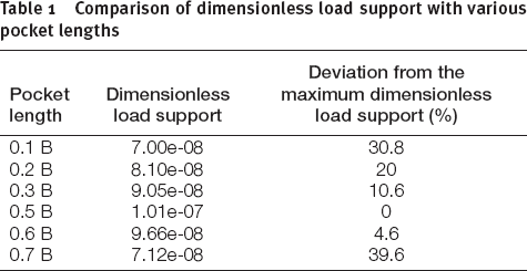
= 0.5 B is 1.01e-07, which is 10.6% higher than Xb = 0.3 B. The calculation results of load support with various pocket lengths are presented in Table 1.
) for X
b
= 0.5 B is 1.01e-07, which is 10.6% higher than Xb = 0.3 B. The calculation results of load support with various pocket lengths are presented in Table 1.
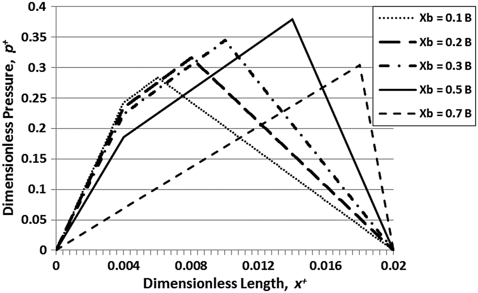
Pressure distribution for pocketed slider bearing with various pocket lengths (X b = 0.1 B, 0.2 B, 0.3 B, 0.5 B and 0.7 B).
Comparison of dimensionless load support with various pocket lengths
The effect of slip zone
Fig. 6 describes the schematic representation of pocketed slip bearing where the slip zone (L s ) is applied. It is noted that the level of slip (hydrophobicity) is represented by the slip coefficient (α). The slip is positioned on the stationary surface as well as on the pocket surface.
Schematic of slip zone for various analyses.
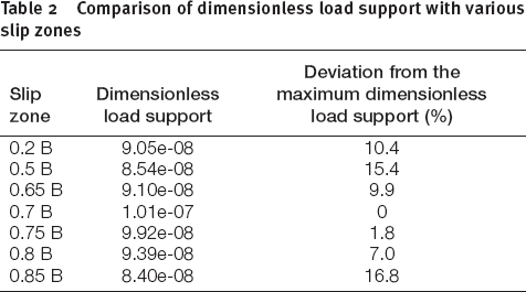
As reflected in Fig. 7, the peak of dimensionless pressure distribution is the highest for the slip zone L s = 0.75 B. However, the load support reaches peak performance at the slip zone (L s = 0.65–0.7 B). This shows that an optimal slip zone for lubricated contact with non-Newtonian is similar to Newtonian-lubricated contact.5, 6 Therefore, it underlines that the pressure distribution will decrease if the slip zone is applied along pocket area. The completed calculations of load support with various slip zones are summarized in Table 2.

Pressure distribution for pocketed slider bearing with various slip zones (L s = 0.2 B, 0.5 B, 0.65 B 0.7 B, 0.75 B, 0.8 B and 0.85 B).
Comparison of dimensionless load support with various slip zones
Effect of slip coefficient
Fig. 8 shows that the greater the slip coefficient (α), the higher the maximum pressure is. However, when the slip coefficient (α) is above 0.05, its influence on the maximum pressure is not extensively significant. It means that an optimal slip coefficient (α) is 0.05.
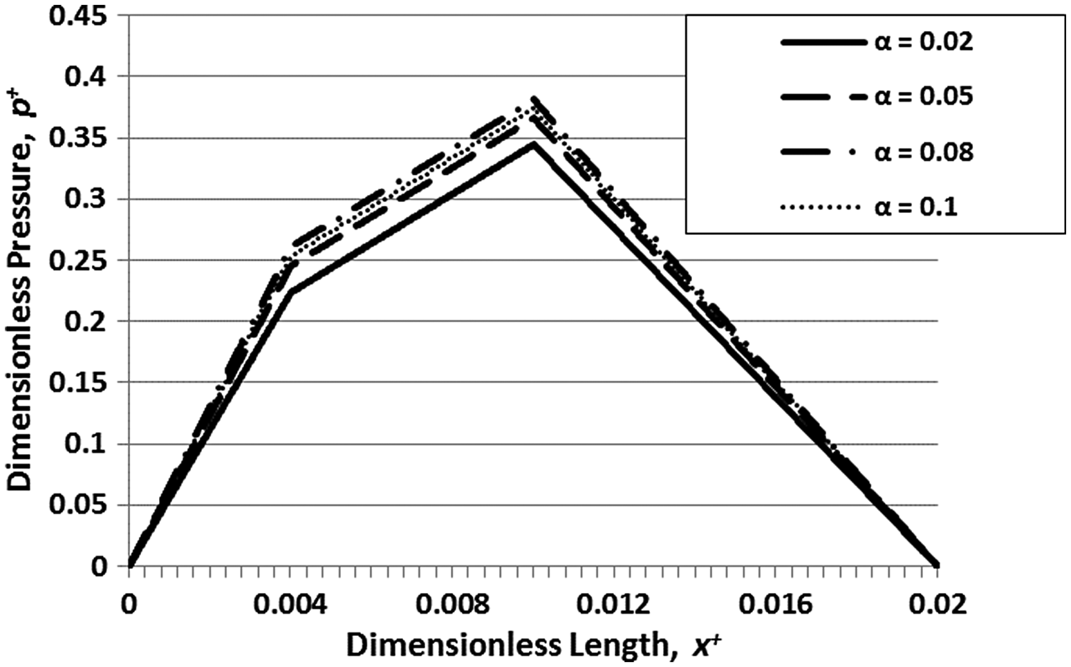
Pressure distribution for pocketed slider bearing with various slip coefficients (α = 0.02, 0.05, 0.08 and 0.1).
Conclusions
In the present study, pocketed slider bearing with non-Newtonian lubricant with slip boundary was investigated using numerical analysis. Based on the analysis mentioned earlier, the following conclusions can be drawn:
An optimal slip zone as well as slip coefficient is highlighted. The characteristic of non-Newtonian is similar to Newtonian fluid with respect to pressure distribution. The pocket depth gives the highest value of load support when it is equal to film thickness.
List of symbols
length of slider bearing
local film thickness
inlet film thickness
outlet film thickness
pocket height
texture thickness
Inlet length
slip zone
power-law index
fluid film pressure
Reynolds number
moving velocity
load carrying capacity,

pocket length
slip coefficient
slip coefficient at stationary surface
slip coefficient at moving surface
apparent viscosity coefficient, a material constant
Dimensionless parameters


Footnotes
Acknowledgements
The research was originally accepted for and presented at MITC 2015.