
Abstract
Sliding between crossed cylinders, one large work material cylinder and one smaller coated tool cylinder, can be used to simulate the contact between a chip and the rake face of a cutting tool. However, accurate simulations require the mode of material transfer in the test to match that in real machining. The mode is strongly dependent on normal load and sliding speed, and it is classified into four types; negligible oxide, only iron oxide, iron oxide and alloy oxide, and metallic transfer with coating cracking. A high load proved to be the most important to accurately simulate the mode and area of material transfer occurring in milling. The diameter of the work material cylinder influences the shape of the contact mark, but has no influence on the mode of transfer. This means smaller work material diameters can favourably be used, reducing costs and facilitating handling during both tests and analysis.
Introduction
Machining, such as turning, drilling and hobbing, is recognised as one of the most important processing methods for structural component manufacturing, mainly because it enables high-precision processing. However, the cost of a machining process is significantly higher than that of materials or other processes like forging. 1 An improvement of the productivity of machining is thus the most efficient way to decrease the cost of the manufactured components. There are several criteria for machinability, such as tool life, chip breakability and surface integrity. Tool life is generally considered the most important when machining structural steels.
When machining steels, the interface between the chip and the cutting tool is under high pressure and high temperature due to the large deformation at high speed close to the tool edge. The maximum normal stress on the tool has been reported to be about 500–1600 MPa, depending on the work materials and machining conditions.2, 3 It is also reported that the maximum temperature may exceed 1000 °C at the tool/chip interface. 2 These severe conditions promote strong material transfer between the chip and the rake face of the cutting tool. It is well-known that such material transfer can have strong effects on the cutting performance and tool life. For example, it is reported that the oxide layer formed on the rake face at high cutting speed prolongs the tool life. 4 − 6 Thus, in order to improve the tool life, it is of great interest to understand the mechanisms of material transfer.
Since machining is a complex process, several different test methods have been utilised to simulate the contact between the chip and the rake face. 7 − 10 In recent years, Gerth et al. 11 have proposed a sliding test with crossed cylinders for reproducing work material transfer in milling. In this test, the chip forming in the primary shear zone during cutting is excluded and only the contact between the chip and the rake face is imitated. Contact parameters, such as normal load, sliding speed and contact mode (intermittent or continuous contact), can easily be controlled.
This test method has been applied to simulate material transfer when PVD coated high speed steel (HSS) tools are slid against a case hardening steel. It was revealed that material transfer on the tools was often divided into two regions; one with alloy oxide and one with iron oxide. 11 − 13 It was reported that the alloy oxide is dominating in the central region of the contact, defined as zone I, where the contact pressure and the temperature are higher and where there is a low oxygen supply from the environment. The iron oxide is formed in the outer region of the contact, defined as zone II, i.e. at low pressure, low temperature and a high oxygen supply. It was proposed that the formation and properties of the transfer layers depend on the operating conditions. Unfortunately, the contact parameters in these studies 11 − 13 were limited to quite narrow ranges, simulating only certain cutting operations. The influence of normal load specifically has not been studied at all. Knowledge of this is valuable as it will tell how an increase in load, caused by e.g. an increased cutting feed and/or an increased cutting depth, influences material transfer and the cutting process.
With focus on oxide formation, this study investigates the influence on material transfer from normal load, combined with different sliding speeds and work material diameters. The parameters are varied over broad ranges, covering a multitude of different cutting conditions and extending beyond those of typical milling. It allows for optimisation of the sliding test conditions to properly simulate material transfer in milling.
Material and methods
Materials
Cylinders with a diameter of 5 mm and a length of 20 mm were produced from a powder metallurgy HSS ASP2023 with a hardness of about 850 HV. The cylinders were polished and coated with PVD TiN. After coating deposition, the cylinders were polished to a Ra value of 0.083 ± 0.009 μm. The coating thickness is approximately 3.6 μm. The coating hardness, measured using nanoindentation with an indent depth of 200 nm, is 25 ± 2 GPa. A case hardening steel, EN-ISO 20NiCrMo2, see Table 1, was used as the work material, as in the previous studies. 11 − 13 The steel was composed of ferrite and pearlite microstructure and the hardness of the steel was approximately 180 HV.
Chemical composition of the work material 20NiCrMo2 (wt-%)

Chemical composition of the work material 20NiCrMo2 (wt-%)
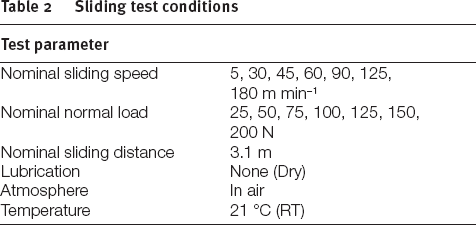
The test rig was the same used in the previous studies, 11 − 13 see Fig. 1. It consists of two crossed cylinders sliding against each other. The small TiN coated HSS cylinder represented the rake face of the tool and the large rotating work material cylinder represented the chip. Work material cylinders of four different diameters were used: 139, 110, 80 and 54 mm, all controlled to within 0.6 mm of those values. The work material cylinders were turned right before starting the test to make sure a clean surface was achieved. The turning was carried out with coated carbide tools under dry condition, with a cutting speed of 265 m min−1, a feed of 0.061 mm rev−1 and a cutting depth of 0.1 mm. The small cylinder was pressed against the large cylinder with a normal load applied by a spring. The normal load was kept constant during the test. In order to avoid repeated sliding in the same track, the tool cylinder was fed in the lateral direction during the tests. This results in a contact more similar to that in actual machining. Based on a previous study in the same test rig, 12 concluding that the same type of oxide layer formed in both intermittent and continuous sliding, all tests in this work were performed in continuous sliding mode. The tests were performed at room temperature with conditions shown in Table 2. The sliding speeds and the normal loads were varied in the intervals 5–180 m min−1 and 25–200 N, respectively. Generally, the sliding speed and normal load were controlled to within 2.3 and 1.8%, respectively. For the slowest test, the speed differed more, about 5.2 m min−1 instead of 5 m min−1. The total sliding distance was 3.1 ± 0.2 m which was almost the same as that in the previous study. 12
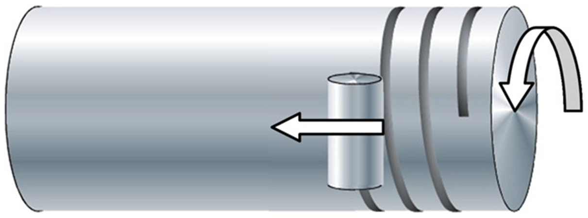
Schematic view of the contact situation in the crossed cylinders test setup
Sliding test conditions
After the tests, the tool cylinder surfaces were observed using optical microscopy, scanning electron microscopy (SEM) and energy dispersive X-ray spectroscopy (EDS). The electron beam acceleration voltage for SEM imaging and EDS analysis was either 10 or 20 kV.
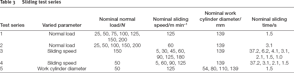
Five series of experiments with different contact parameters as shown in Table 3 were performed. The varied contact parameters were normal load, sliding speed and work cylinder diameter. Only one of the three parameters was varied in each test series keeping other parameters constant, i.e. the varied parameter was normal load in series 1 and 2, sliding speed in series 3 and 4, and cylinder diameter in series 5. Different constant sliding speeds were used in series 1 and 2, and different constant normal loads were used in series 3 and 4. The sliding speed was changed by adjusting the rotational speed of the work cylinder. The rotational speed was also adjusted in series 5 to make the sliding speeds the same when cylinders with different diameters were used. The sliding distance was kept almost the same for all tests by adjusting the sliding time.
Sliding test series
Sliding test series
Influence of normal load on material transfer
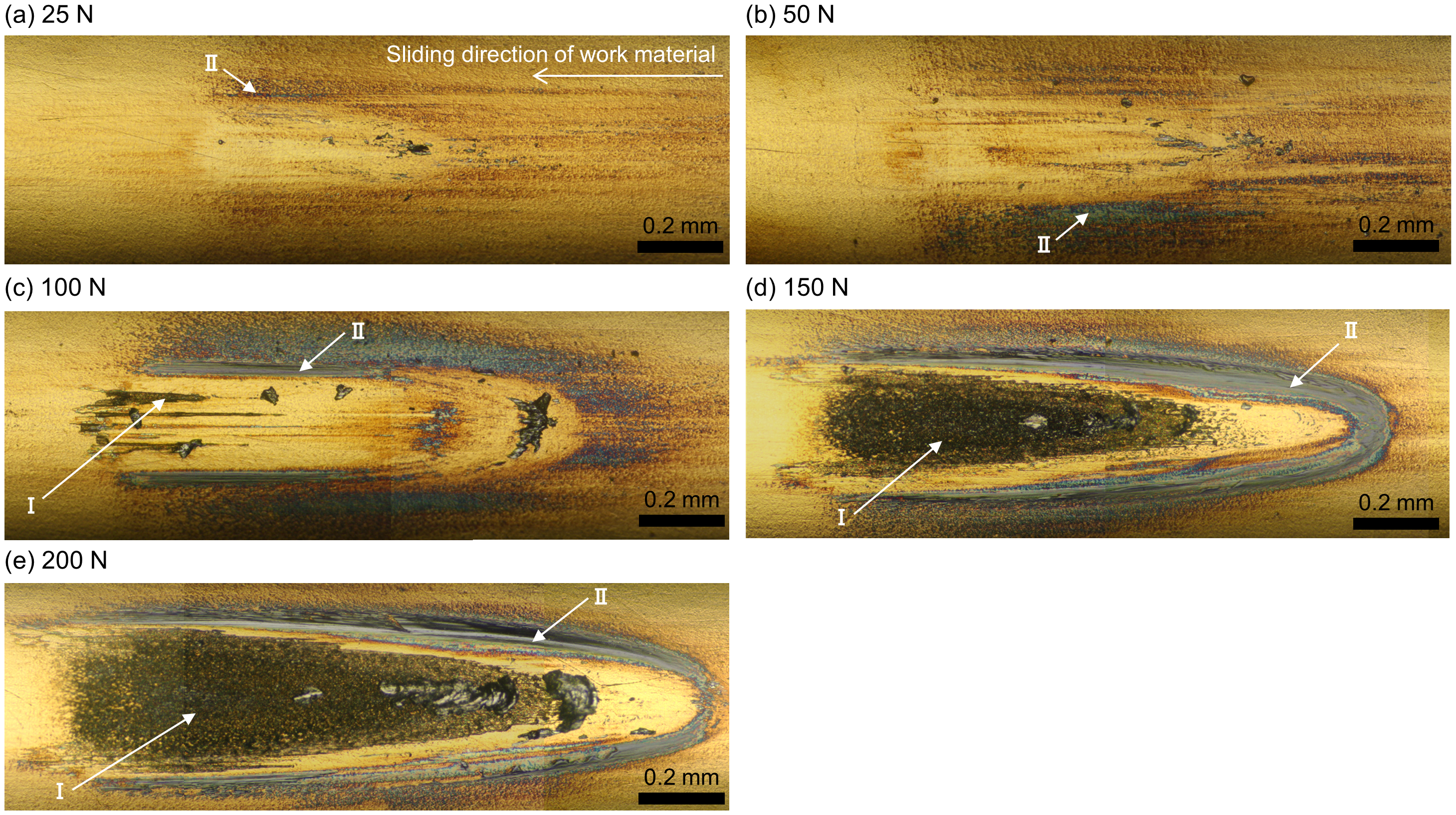
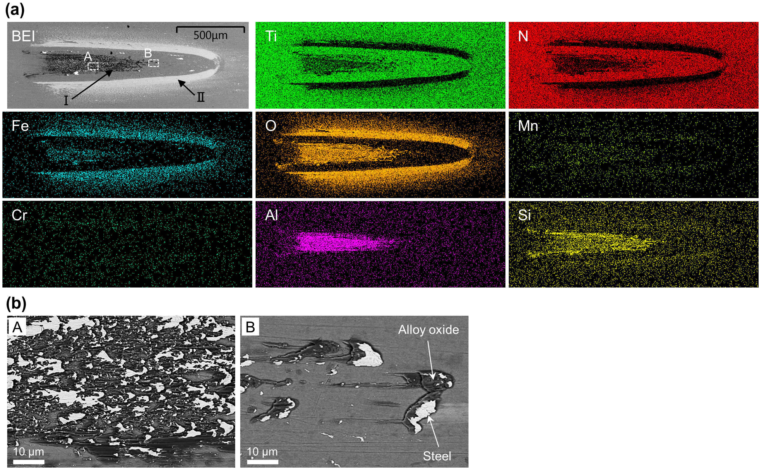
In the test series 1, a constant sliding speed of 125 m min−1 and different normal loads were used. At the low load of 25 N, zone II (light grey region) covered a relatively wide area, while zone I was not seen, see Fig. 2a. Zone II was an iron oxide containing small amounts of Si, Mn and Cr, see Fig. 3a. As the load was increased stepwise to 100 N, zone II shrunk towards the rim of the contact mark, while zone I (black region) appeared in the inner region and expanded outwards, see Fig. 2b–d. Zone I was mainly an alloy oxide including Al, Si and Mn, see Fig. 3b. When the load was 125 N, a typical zone I was not seen in the very middle, see Fig. 2e. Instead small cracks in the coating and substantial material transfer appeared in the region pointed out by the white rectangle in Fig. 2e. At 150 N, clear cracks and transferred lumps were observed, see Figs. 2f and 4. The alloy oxide of zone I seems to have been rubbed off, as the strong signal from N in the central region indicates that the coating is exposed, see Fig. 4. Cracks seem to promote material transfer, and the EDS maps indicate that this transfer is not in the form of an oxide but steel itself from the work material. No exposed substrate was observed as shown by the absence of a signal of W, which is an abundant element in the substrate. Further increase in normal load to 200 N resulted in huge metallic steel transfer, see Figs. 2g and 3c.

Optical microscope images of the contact marks on the TiN coated tool cylinders after sliding with a sliding speed of 125 m min−1 and different normal loads against a work cylinder with a diameter of 139 mm. Black and light grey regions are indicated by zone I and zone II, respectively. Cracks in the coating are indicated by arrows. The sliding direction of the work material is from right to left in the plane of the paper
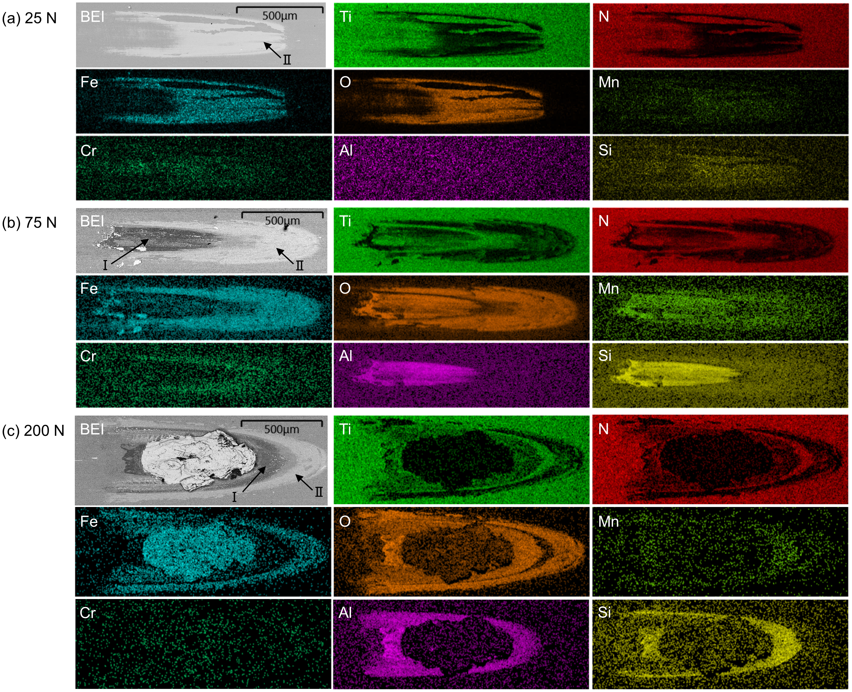
Backscattered electron images and EDS maps of the contact marks on the TiN coated tool cylinders after sliding with normal loads of a 25 N, b 75 N and c 200 N and a sliding speed of 125 m min−1 against a work cylinder with a diameter of 139 mm. The electron beam acceleration voltage was 10 kV
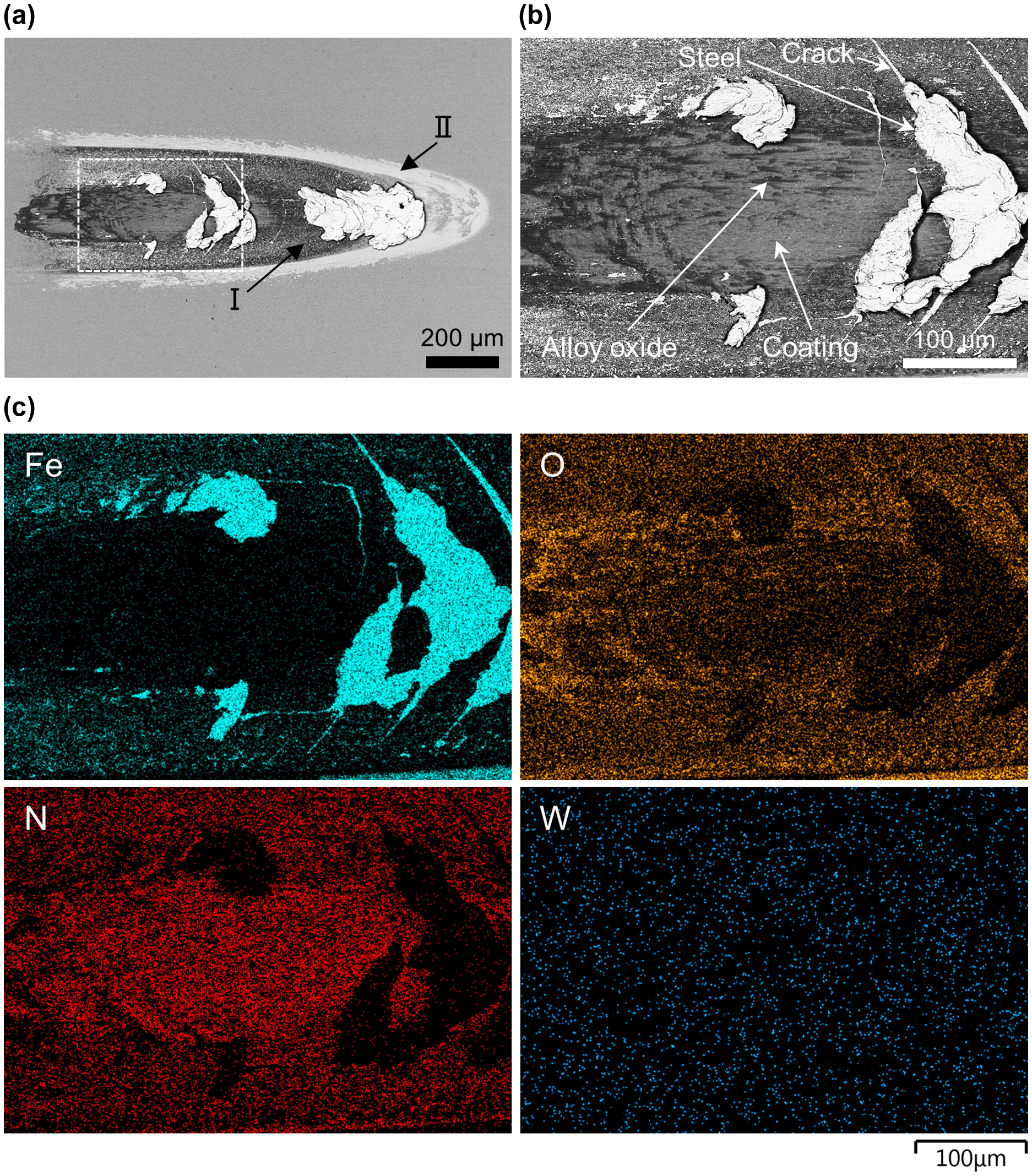
a and b Backscattered electron images and c EDS maps of the TiN coated tool cylinder after sliding with a normal load of 150 N and a sliding speed of 125 m min−1 against a work cylinder with a diameter of 139 mm. a The entire material transfer region, b a magnification of the middle area indicated by the white dashed rectangle in a. The alloy oxide, the exposed TiN coating, cracks in the coating and the metallic steel transfer are indicated by arrows in b. The electron beam acceleration voltages for SEM imaging and EDS mapping were 10 kV and 20 kV, respectively
When using a lower sliding speed of 60 m min−1 in the test series 2, only a very small amount of material transfer was observed at 25 and 50 N, see Fig. 5. At 100 N, zone I and zone II appeared clearly in the inner and outer regions, respectively. Zone I obviously became larger at the higher loads of 150 and 200 N.
Optical microscope images of the contact marks on the TiN coated tool cylinders after sliding with a sliding speed of 60 m min−1 and different normal loads against a work cylinder with a diameter of 139 mm
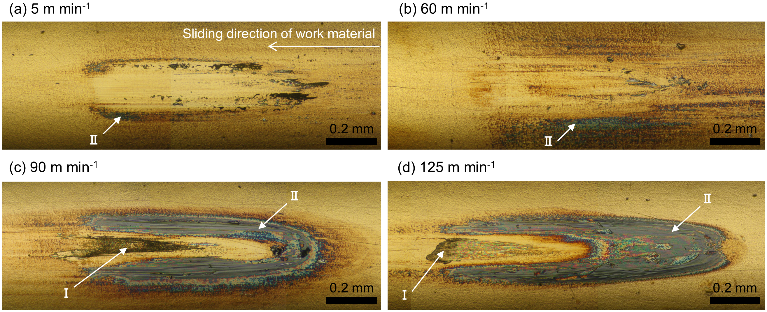
In the test series 3, a constant normal load of 150 N and different sliding speeds were used. At the low sliding speed, almost no material transfer was observed in the central region, see Fig. 6a. The backscattered electron image and EDS maps in Fig. 7 revealed that the small amount of material transfer present in the outer region was an early stage of the iron oxide of zone II. At a sliding speed of 30 m min−1, zone II became clearly visible in the outer region, see Fig. 6b. In the central region, a few small black lumps were observed and confirmed, using EDS, to be an early stage of the alloy oxide of zone I, see Fig. 8. When the sliding speed was increased from 45 to 60 and 90 m min−1, zone I grew from the central region towards the rim, see Fig. 6c–e. As shown in Fig. 9a, at 45 m min−1 and 150 N zone I was an alloy oxide including Al, Si and Mn, with a composition similar to the alloy oxide generated with 125 m min−1 and 75 N in series 1, c.f. Fig. 3b. The Fe map in Fig. 9a shows some Fe content also in the central region. This was analysed at higher magnification using SEM and EDS, and always confirmed to be non-oxidized steel on top of the alloy oxide, see Fig. 9b. At 125 m min−1, cracks and steel transfer along the cracks were observed, as shown in Figs. 6f and 4. The steel transfer became even more dominant at 180 m min−1, see Fig. 6g.

Optical microscope images of the contact marks on the TiN coated tool cylinders after sliding with a normal load of 150 N and different sliding speeds against a work cylinder with a diameter of 139 mm
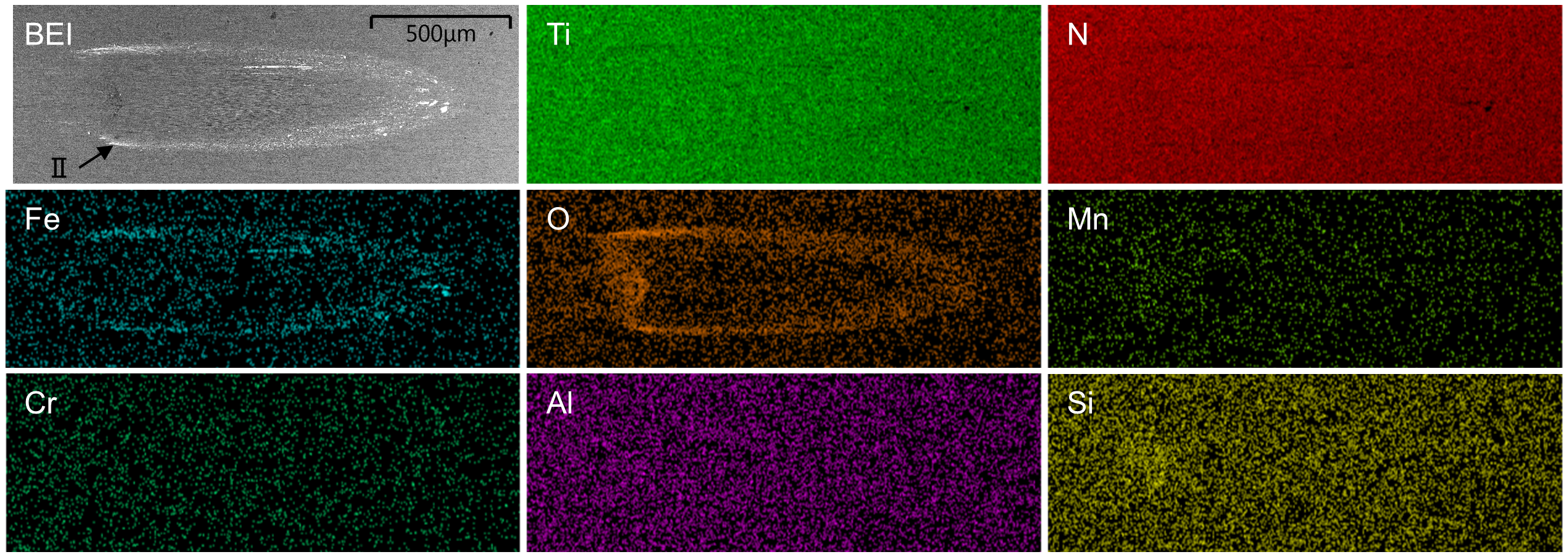
A backscattered electron image and EDS maps of the contact mark on the TiN coated tool cylinder after sliding with a normal load of 150 N and a sliding speed of 5 m min−1 against a work cylinder with a diameter of 139 mm. The electron beam acceleration voltage was 10 kV
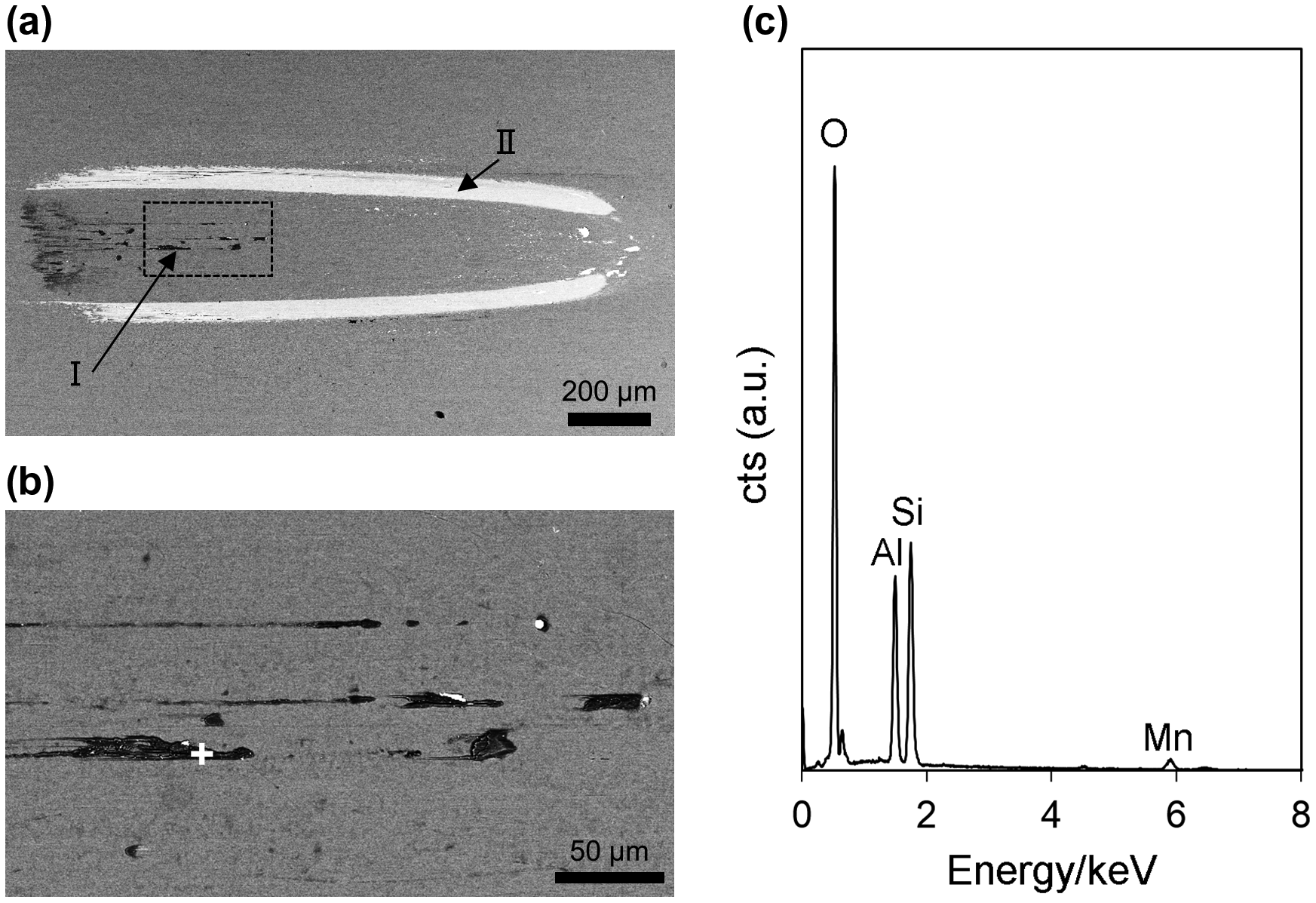
a and b Backscattered electron images and c an EDS spectrum of the contact mark on the TiN coated tool cylinder after sliding with a normal load of 150 N and a sliding speed of 30 m min−1 against a work cylinder with a diameter 139 mm. a The entire material transfer region, b a magnification of the middle area indicated by the black dashed rectangle in a, and c the EDS spectrum obtained at the white cross in b. The electron beam acceleration voltage was 10 kV
Backscattered electron images and EDS maps of the contact mark on the TiN coated tool cylinder after sliding with a normal load of 150 N and a sliding speed of 45 m min−1 against a work cylinder with a diameter of 139 mm. (a) The entire material transfer region and (b) magnifications of the centre (A) and the front (B) areas indicated by the two white rectangles in (a). The alloy oxide and the metallic steel transfer are indicated by white arrows in (b). The electron beam acceleration voltage was 10 kV
When using a lower normal load of 50 N in the test series 4, a very small amount of material transfer was seen at sliding speeds of 5 and 60 m min−1, see Fig. 10. As the sliding speed was increased to 90 and 125 m min−1, zone I and zone II were clearly seen.
Optical microscope images of the contact marks on the TiN coated tool cylinders after sliding with a normal load of 50 N and different sliding speeds against a work cylinder with a diameter of 139 mm
The smaller the work cylinder diameter was, the shorter the length of contact mark and the larger the width of contact mark became, see Fig. 11, showing the results of the test series 5. However, the modes of material transfer did not change by changing the cylinder diameter. No strong relationship between the areas covered with transferred material and the cylinder diameter is seen, see Fig. 12.
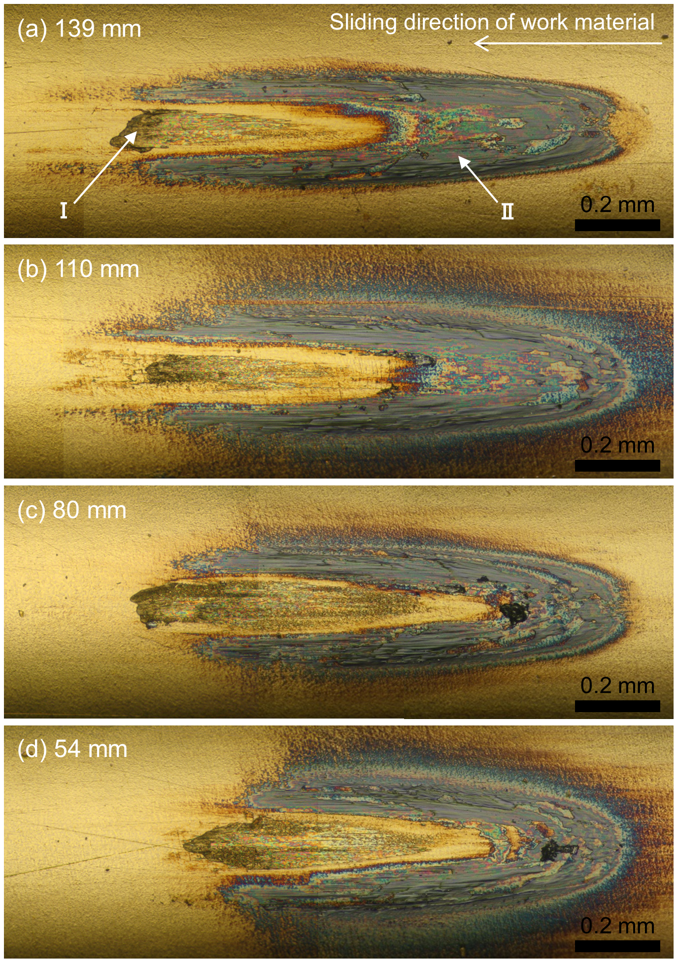
Optical microscope images of the contact marks on the TiN coated tool cylinders after sliding with a sliding speed of 125 m min−1 and a normal load of 50 N against steel cylinders with diameters of (a) 139, (b) 110, (c) 80 and (d) 54 mm
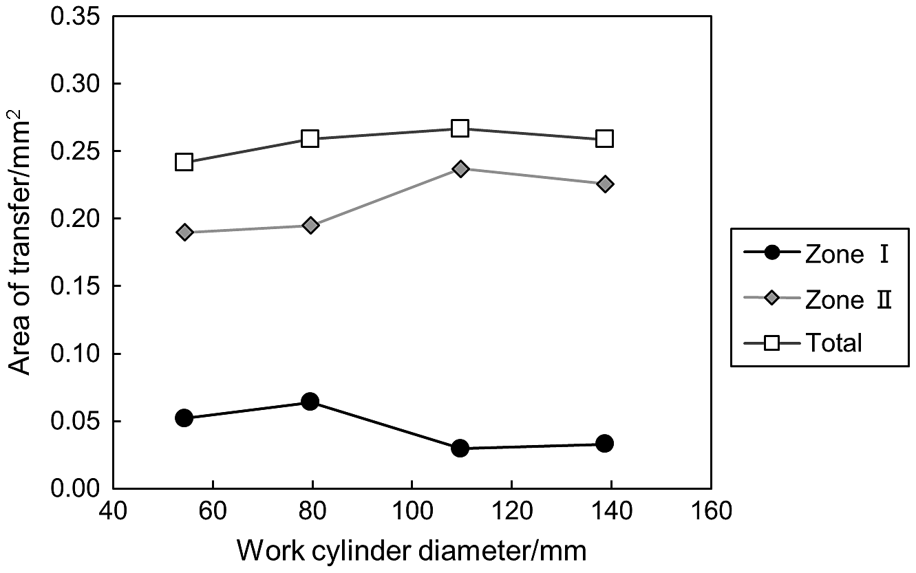
Areas of transferred material plotted against work cylinder diameters when using a sliding speed of 125 m min−1 and a normal load of 50 N. Total means the sum of the areas of zone I and zone II. The areas were measured using optical microscope images
The mode of material transfer
The experimental results in this study revealed a strong influence of experimental conditions on the material transfer from a case hardening steel to the surface of a TiN coated tool. The characteristic modes of material transfer are shown in the sliding speed–normal load diagram in Fig. 13. Each test is classified into one of four types of material transfer; negligible oxide, only iron oxide, iron oxide and alloy oxide, and metallic transfer with coating cracking. It should be noted that this diagram focuses on characteristic features in surface appearance. Minor amounts of other transfer modes may co-exist but these are not considered in this classification. The dashed lines in Fig. 13 show the iso-lines of the heat generation during sliding, estimated by the very simplified model

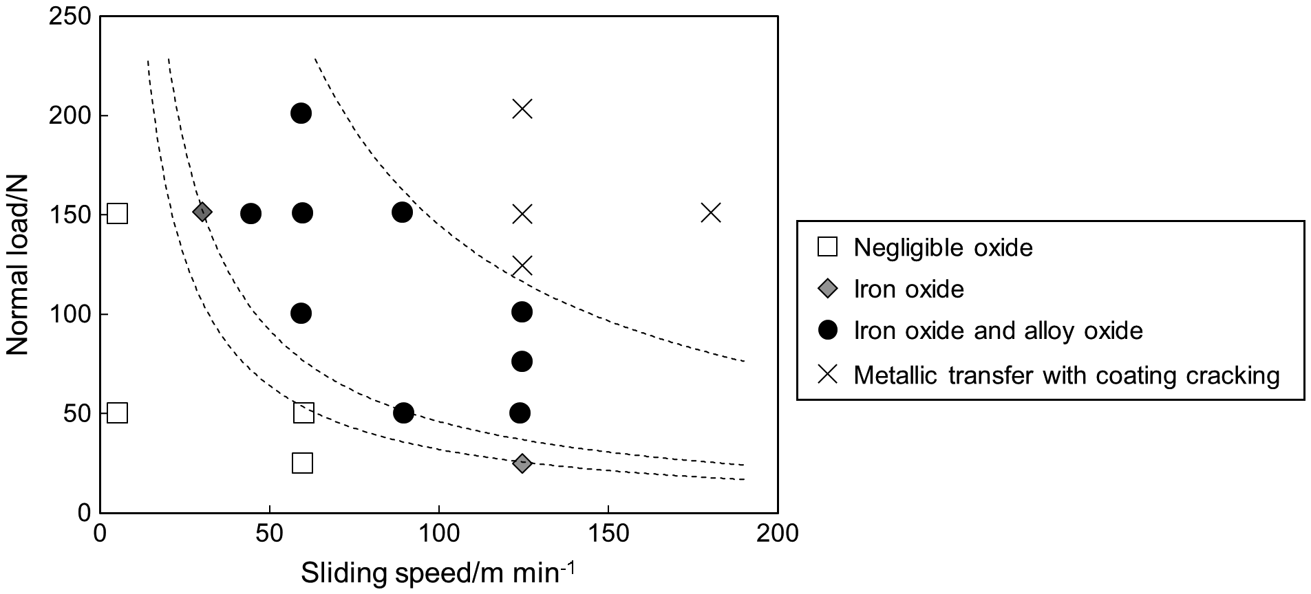
The characteristic modes of material transfer at different sliding speeds and normal loads. Each test is classified into one of four types: negligible oxide formation, only iron oxide formation, iron oxide and alloy oxide formation, and metallic transfer with coating cracking. The dashed lines are iso-lines of the heat generation estimated by a very simplified model
where Q, μ, W and v are the heat generation rate, the dynamic friction coefficient, the normal load and the sliding speed, respectively. 14 Here, the friction coefficient was not considered, because the friction coefficient varied only slightly between the tests; always in the range 0.85–1.1 as long as the coating remained intact or only showed minute cracks. The iso-lines properly divide different modes of material transfer. This means that the heat generation, caused by an increase in normal load or sliding speed, is a dominant factor for the oxide formation and the coating cracking.
The influence of sliding speed was investigated also in the previous study, 13 although the experimental conditions were different from those in the present study. It was reported that almost no oxide formation occurred at low sliding speed. The iron and alloy oxides were formed only as the sliding speed, and thus heat generation, was increased. At even higher sliding speed, the large heat generation caused thermal softening of the substrate. This made the support of the coating insufficient, causing coating deformation and cracking. Ultimately, the coating was destroyed in the centre of contact region, exposing the HSS substrate and initiating work material transfer to the exposed substrate. Our results in Figs. 6 and 10 are fully consistent with those results. In addition, this study shows that at higher normal load the oxide formation and the cracking of coating began to occur at lower sliding speed. As shown by the equation above, an increase in normal load also increases the amount of heat generated in a sliding contact. Such an increase in heat generation will promote the generation and growth of oxide. However, a too high normal load leads to higher heat generation than the coated tool can endure. This leads to plastic deformation of the substrate and destabilises both the coating and the growing oxide. It promotes rubbing off of the alloy oxide, cracking of the coating and then metallic transfer of work material.
Although each test was performed only once, the contact parameters were systematically varied over broad enough ranges to make the results on trends in material transfer reliable.
In the previous study, 11 it was pointed out that the area of zone II was larger than that of zone I in the sliding test, although the area of zone I was larger in actual milling. This is an important point because the areas of the material transfer were concluded to largely influence the friction behaviour. 11 The sizes of zone I, zone II and the total area with material transfer, obtained with different normal loads in this work, are plotted in Fig. 14. In this figure, the condition of the previous study, 11 which resulted in too small zone I, is indicated by a dashed line. The sizes of zone I and the total area increase with increased normal load. This is reasonable because in this test the work material will experience macroscopic plastic deformation. The contact area is likely determined mainly by the hardness of work material and normal load, and thus it increases as the normal load increases. In contrast, zone II becomes slightly smaller as the load is increased. This might be because the distance oxygen from environment can penetrate into the mark is shorter at higher contact pressure. Testing at a higher load condition results in a higher relative coverage by zone I, see the percentage covered by zone I in Fig. 14. The simulating sliding test can thus be made more similar to the situation in real milling by using a higher normal load, but still within the range where there is no coating cracking according to Fig. 13.
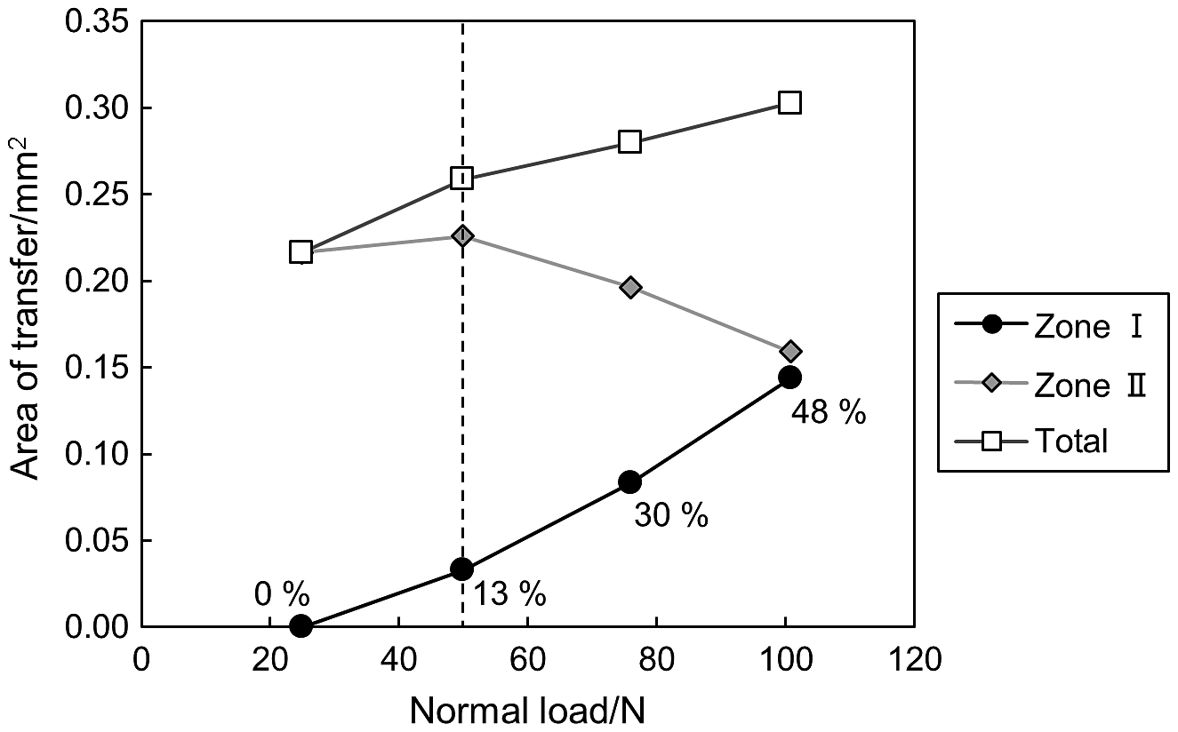
Areas of transferred material plotted against normal loads when using a sliding speed of 125 m min−1 and a work cylinder with a diameter of 139 mm. Total means the sum of the areas of zone I and zone II. The ratios between zone I and total are shown as percentages in the figure. The areas were measured using optical microscope images, and only conditions where no rubbing off of the alloy oxide or large metallic transfer had occurred are included. The condition corresponding to the previous study 11 is indicated by a dashed line
Regarding the influence of the work cylinder diameter, the shape changes of the contact mark match that expected from Hertz contact theory, i.e. a larger work cylinder diameter gives a more elliptical mark, c.f. Fig. 11. The contact area size is also expected to increase slightly when increasing the cylinder size, based on the Hertz theory. On the other hand, the contact area is determined mainly by the hardness of work material and normal load as explained above, and thus it did not change with the different cylinder diameters, c.f. Fig. 12. This means there will not be any significant change in contact pressure with different cylinder diameters, and therefore the mode of material transfer will not change largely. The pressure distribution will change, however, and this will affect the shape of the contact mark and the distribution of material transfer. In previous studies, 11 − 13 relatively large work cylinders, about 140 mm in diameter, have been used. This has the benefit of extending the contact mark which facilitates analysis. However, larger cylinders are larger in mass, the cost to prepare the work material is higher and the handling of samples is also more cumbersome. The results obtained in this study clearly show that the test is quite insensitive to the choice of work material diameter when characterising the material transfer, and that cylinders as small as 54 mm in diameter can successfully be used instead of e.g. the 140 mm used in previous studies. 11 − 13 This fact allows both cost savings and more efficient experiments.
The material transfer occurring at the interface between a case hardening steel and a TiN coated HSS tool was investigated in a crossed cylinders sliding test. Main foci were on the influence of normal load and the optimisation of the sliding test conditions for proper simulation of the contact situation in real milling. The main conclusions are as follows:
The mode of material transfer was strongly dependent on the normal load as well as on sliding speed. The contribution from both parameters is explained by the heat generation in the sliding contact. From a low load and/or low speed situation to a high load and speed condition, i.e. from low to higher heat generation, the modes of transfer are classified into four types: neither iron oxide nor alloy oxide are generated in significant amounts mainly an iron oxide forms in the outer region also an alloy oxide starts to form in the central region the alloy oxide is rubbed off, and metallic transfer with coating cracking occurs Using a high normal load, avoiding the range where there is coating cracking, is important to appropriately simulate the mode and area of material transfer occurring in real milling. In the interval 54–139 mm, the diameter of the work material cylinder does not affect the mode of material transfer, only the shape of the contact mark. Cylinders as small as 54 mm in diameter can successfully be used for efficient experiments simulating material transfer.
Disclosure statement
No potential conflict of interest was reported by the authors.
Footnotes
Acknowledgements
Financial support from Nippon Steel & Sumitomo Metal Corporation is acknowledged.