
Abstract
Nanosize B4C and/or MoS2 particles reinforced AA2219 alloy composites were prepared using the stir casting process. The wear properties were evaluated for several speed (3.14–5.65 m s−1), load (10–50 N) and distance (0–2500 m) conditions. The nanoparticles dispersion, density, wear resistance, morphology of the worn surface and loose wear debris were discussed in detail. The wear resistance improvement results by nanoparticle addition correspond well with the hardness. Between the nanocomposites, hybrid composites show significantly higher wear resistance for all load, speed and sliding distance conditions. The better wear resistance is attributed to the matrix strengthening by nanoparticles and the lubricant-rich tribolayer controlled wear in the hybrid composites. The intensity of abrasive, oxidation and delamination wear mechanisms decide the wear rate at any particular wear testing condition.
Keywords
Introduction
In recent days, aerospace and automobile designers are looking for lightweight and at the same time, high performance materials. This requirement drives material scientists to shift focus to composite materials from conventional monolithic metallic alloys. Among the metals, aluminium is the most commercially used lightweight, cost-effective alloy in aerospace and automobile industries. The lightweight properties have high influence in minimising cost and environment pollutions through reducing the weight and fuel consumption. 1 However, the strength, thermal stability and tribological properties of these alloys are still a concern and need to be improved. In 1990s, the ceramic particle reinforced Al composites, a class of metal matrix composites (MMCs), emerged to replace the conventional Al alloys especially in tribological applications such as sliding contacts, piston rings, brake rotors, clutch, brake shoes or pads and so on. 2 The presence of particle reinforcements helps to improve the wear resistance by resisting the matrix plastic deformation in addition to enhancing the high specific strength, stiffness and damping capacity. Many processing methods such as stir casting, spray deposition, squeeze casting, mechanical alloying and powder metallurgy were established to fabricate aluminium matrix composites (AMCs). Among these processing methods, the stir casting (liquid state) method is most widely used because of its low capital cost, excellent bonding characteristics between the matrix and the particles, near net shape and high volume production. 3 In this process, second phases are mixed with a molten matrix by means of mechanical stirring. The stirring action ensures the uniform dispersion of second phases and also, refines the matrix microstructure by breaking dendrites during solidification. 4
Among the Al alloys, the Al 2219 alloy is quite popular in cryogenic applications because of its superior specific strength and stiffness, excellent formability and fracture toughness, improved cryogenic properties and outstanding weldability. 5 Currently, this alloy is extensively used in rocket fuel tanks and airframe contact parts. 6 Thus, this alloy is selected in our study. Next important constituent responsible for mechanical, thermal and tribological properties improvements is particle reinforcements. Variety of particles (Al2O3, SiO2, TiC, B4C, SiC, TiB2, Si3N4, MgO, mullite and Al4C3) are used as reinforcements in AMCs. 7 Among these particles, B4C particles are least studied. The B4C is the third hardest material which comes after diamond and cubic boron nitride. The unique properties of B4C such as high impact resistance, good wear resistance, high melting point (2450 °C) and elastic modulus (445 GPa), outstanding resistance to chemical agents, high neutron absorption capacity and low density (2.51 g cm−3) makes this an ideal reinforcement in Al alloy matrix.8–11 Besides the matrix and hard particle reinforcements, the lamellar structure soft particles (referred as solid lubricants) such as Gr, MoS2, h-BN, Cu2S and Sb2S3 are preferred to be added in the composites used in the tribological applications. 2 These soft particles assist in improving the wear resistance, oxidation resistance and stabilise the friction.12, 13 Also, they help in reducing counter surface wear by forming tribolayer at the interface. 2 Among the solid lubricants, MoS2 is found to be superior because of its intrinsic lubricity properties and high temperature stability. 13 Hence, it is selected in our study.
Recent researches suggest that the particle size has a profound effect on mechanical and tribological properties of the AMCs. Particularly, the size ranges of nanoscale showed tremendous mechanical properties improvements through several mechanisms such as particle-assisted grain refinement, Orowan strengthening, work hardening, dislocation strengthening through elastic modulus mismatch and thermal mismatch, dislocation and particle interaction effects.14–16 With respect to tribological properties, two contrasting hypothesis exist. In one hypothesis, the large size particles of several microns are expected to improve the wear resistance by deeper embedment in the matrix. The deeper embedment delays the removal of particles and thus the particle load bearing effects persist for longer cycles. Hence, the wear resistance is improved. 17 On the other hand, the small size particles of sub micron or nanoscale are expected to improve the wear resistance by matrix strengthening effects. Further, the interparticle spacing is significantly reduced as the size reduces. This increases the number of particles per unit area and thus helps in improving the friction and wear resistance by more particles and counter surface metal contacts. 18
There are limited wear reports on metal matrix nanocomposites. In particular, the studies on dry sliding wear behaviour of Al matrix/B4C nanocomposites are very few. Harichandran et al. 19 investigated the wear behaviour of micro (70 μm) and nanosize (80 nm) B4C-reinforced Al matrix composites processed by ultrasonic cavitations method. The wear rate of nano B4C particle-reinforced AMCs was significantly lesser than micro B4C particle-reinforced AMCs. They attributed the nanoparticle-assisted grain refinement to the wear resistance improvements. Abdollahi et al. 20 have compared the wear resistance of AA 2024 alloy with the nanosize B4C (10 nm) particle-reinforced AA 2024 matrix composites under the low load (20 N) and sliding speed (0.6 m s−1) condition. It was found that the wear rate of nanoparticle-reinforced composites is about 33% of that of AA 2024 alloy. 20 Alizadeh et al. 21 processed the nano B4C particle (80 nm) reinforced AA 2024 matrix composites by the combination of mechanical milling and hot extrusion processes. They have also observed significant improvements in wear resistance by nanosize particle additions. The wear resistance and tensile properties increases with an increase in volume fraction of B4C nanoparticles. 21 From the above reports, it is clear that there is a scope to improve the wear resistance by nanoceramic particle additions in AMCs.
Although the studies on wear behaviour of nanoceramic and solid lubricant particles-reinforced AMCs have not been conducted yet, there are few reports on wear behaviour of micron size ceramic and lubricant particles reinforced AMCs. For instance, Kumar et al. 22 investigated the wear behaviour of AMCs reinforced with micron size B4C (90 μm) and MoS2 (1.3 μm) particles processed by stir casting techniques. The results showed that the increase in MoS2 addition up to 5 wt% has a significant influence in improving the wear resistance of hybrid composites. This improvement is not affected by increasing sliding velocity (1.26–6.30 m s−1), load (10–50 N) and/or sliding distance (500–2500 m).
In light of the facts of no wear reports on nanoparticles-reinforced Al matrix hybrid composites and to provide a clear understanding on particle size especially in nanoscale effects on wear resistance of AMCs, the present work is designed. Two types of nanocomposites, one without lubricant (AA2219/B4C) and one with lubricant (AA2219/B4C/MoS2) were developed by stir casting techniques. The wear behaviour of these composites was examined in a range of speed (3.14–5.65 m s−1), sliding distance (500–2500 m) and load (10–50 N) conditions to understand the nanosize and hybridisation effects.
Experimental procedures
In this present work, the matrix was selected as an AA 2219 alloy. The chemical composition of the AA 2219 matrix is shown in Table 1. The ceramic (hard) and solid lubricant (soft) particles used were n-B4C and MoS2, respectively. The size range of both the particles was measured using GEMINI ULTRA 55 high resolution scanning electron microscope. The particle size ranges of n-B4C and MoS2 were found to be 30–60 nm and 600–900 nm, respectively, as shown in Fig. 1a and b, respectively. The particles appear irregular in shape. The characteristics of the particles are given in Table 2.
Chemical composition of AA 2219 aluminium alloy (wt)

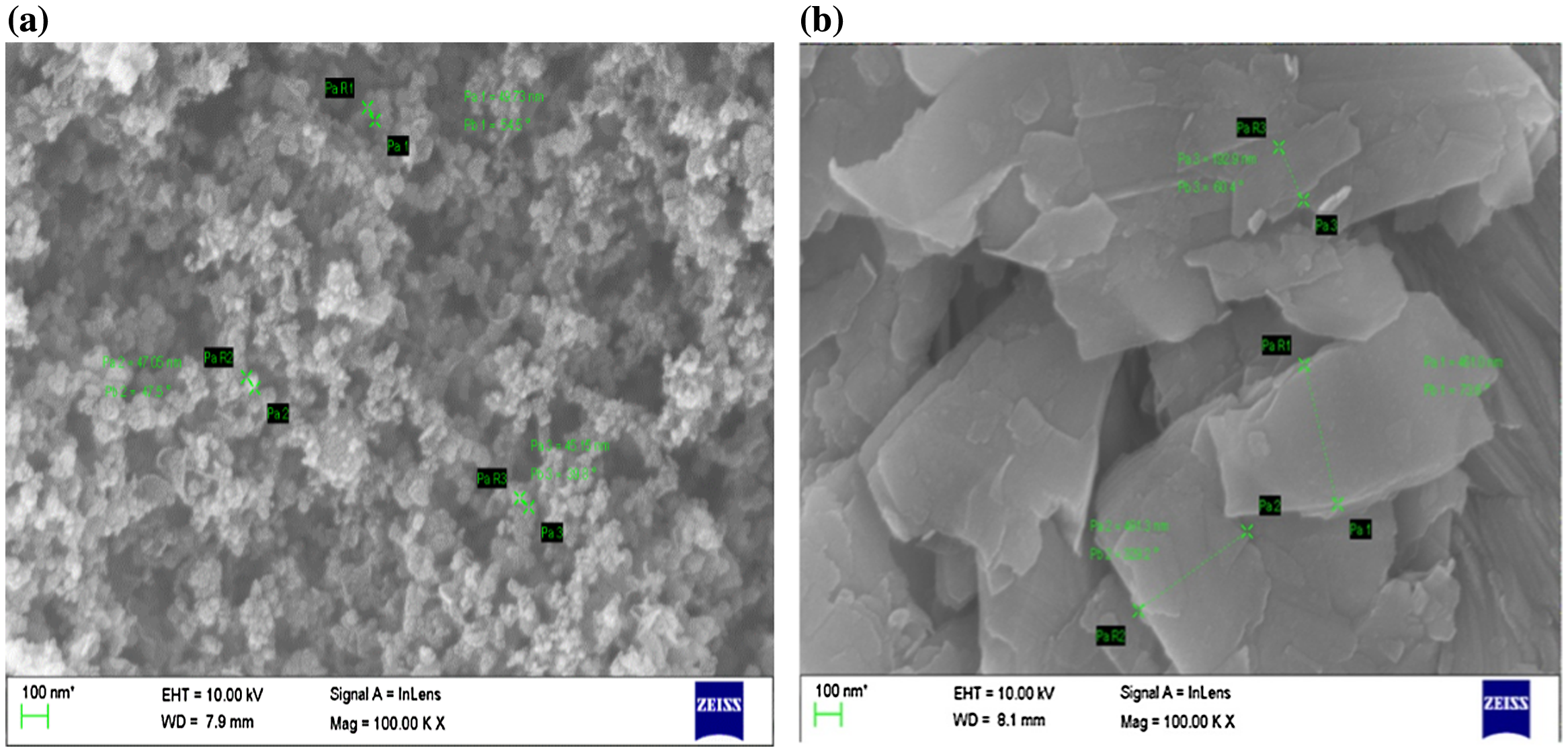
SEM images of a n-B4C particles and b MoS2 particles
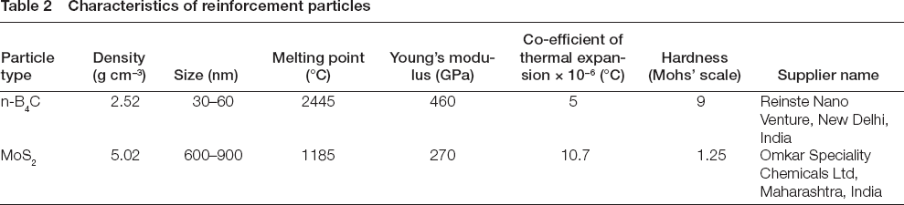
Characteristics of reinforcement particles
The AA2219 alloy was melted at a heating rate of (5 °C min−1) in a resistance-type electric furnace (capacity: 5 kg, power rating: 7.5 kW and heating element: SiC) under the normal air atmosphere. The super heat temperature of the melt was maintained at 750 °C. Both hard (n-B4C) and soft (MoS2) nanoparticles were preheated to 250 °C to remove the moisture and other loose adherent impurities. In order to avoid the clustering of B4C particles, the B4C particles were mixed with potassium fluorotitanate (K2TiF6) halide salt in the ratio of 5:2 to obtain the slurry. The halide salt coupled with the intense stirring action was expected to improve the wettability of the particles with the matrix and to avoid the particle agglomeration. Finally, the MoS2 particles were added. Two types of composites: one with only 2 wt% B4C particles and another with both the 2 wt% B4C particles and the 2 wt% MoS2 particles were prepared. The preheated particles were added into the melt in one or two steps to prepare unhybrid or hybrid nanocomposites in a graphite crucible. In the first step, the slurry of B4C and K2TiF6 was mixed with the Al alloy melt and convulsed with a mechanical stirrer vigorously before and after the addition of B4C particles. The stirring was activated for 5–8 min at a speed of 200–250 rpm. In the second step, the MoS2 particles were added and vigorously stirred to complete the preparation of hybrid nanocomposites. The casting process parameters are given in Table 3. The cast bars were machined to prepare the samples for microstructure, density, hardness and dry sliding wear tests.
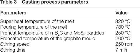
Casting process parameters
The bulk density of the samples was measured using the Archimedes method. The void fraction was evaluated from the measured and theoretical density values. The hardness of the alloy and composites was measured in a micro Vickers hardness tester. The hardness of the composites was measured at a distance of 1, 3, 6, 9 and 12.5 mm from the outer periphery region (edge). The load and indenter type used were 100 gf and pyramidal diamond indenter with the square base having an angle of 136° between the opposite diagonals, respectively. The procedure followed for the hardness test was according to the ASTM E 384 standard. Maximum of three indentations were taken for each location in the sample and the average value for all the readings was reported as hardness. The samples for microstructure were prepared by standard metallographic techniques. The samples were cut into a cylindrical shape and these samples were polished using different grit size abrasive silicon carbide papers (220–1200). After the emery paper polishing, the samples were cleaned, polished with the diamond paste and velvet cloth was used to get a mirror-finished surface. The grain structure, the particles distribution and the nature of the interfaces were observed with the aid of field emission scanning electron microscope (FESEM).
A pin on disc tribometer unit (TR 20LE-PHM-400 model, DUCOM, India), as shown in Fig. 2, was used to conduct dry sliding wear tests. The samples were machined into the pin shape. The height and diameter of the samples were 30 mm and 8 mm, respectively. The steel disc (EN 31 grade) of 120 mm diameter was used as a counter surface. The chemical composition (wt%) of the steel disc was as follows: C: 0.15%, Mn: 0.8%, Si: 0.26%, S and P: 0.04%. The tensile strength, hardness and surface roughness of the disc were 430 MPa, 62 HRc and 1.6 Ra, respectively. Table 4 gives the input parameters for the wear test.
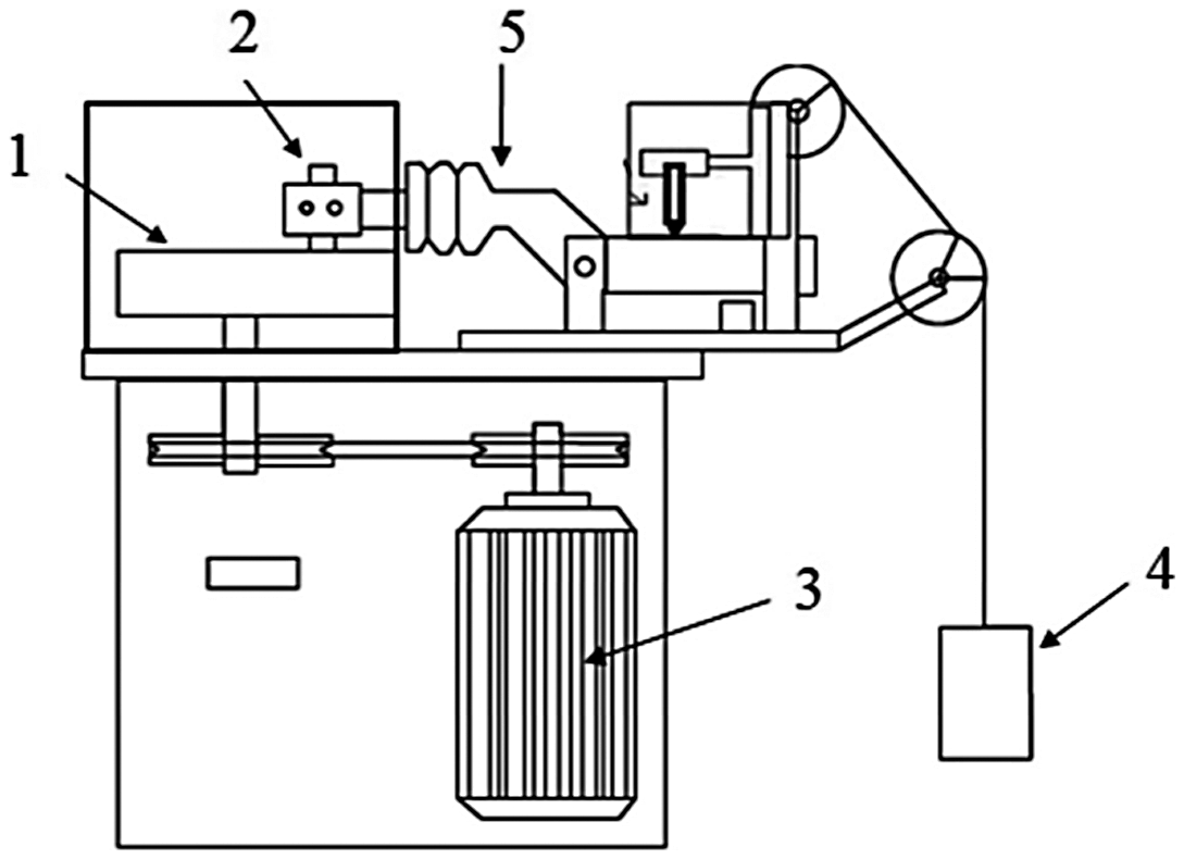
Pin on disc apparatus used for dry sliding wear test (1) Steel disc, (2) Specimen holder, (3) Lever mechanism, (4) Motor and (5) Dead weight
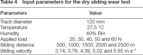
Input parameters for the dry sliding wear test
All the wear tests were conducted in an unlubricated condition. The ASTM G 99-05 standard was followed for the dry sliding wear testing. After each run, the samples were ultrasonically cleaned in acetone, dried and weighed in a digital balance (METTLER, precision: 0.01 mg). The specific wear rate (mm3 Nm−1) of the composites was computed by taking the ratio of the mass loss (g) to the density (g mm−3), the applied load (N) and the sliding distance (m). The wear surface morphology of the composite and the loose wear debris were characterised with the aid of FESEM with energy dispersive spectroscopy (EDS) (GEMINI ULTRA 55) to understand the potential mechanisms operating at different speed and load conditions.
Results and discussion
Microstructure
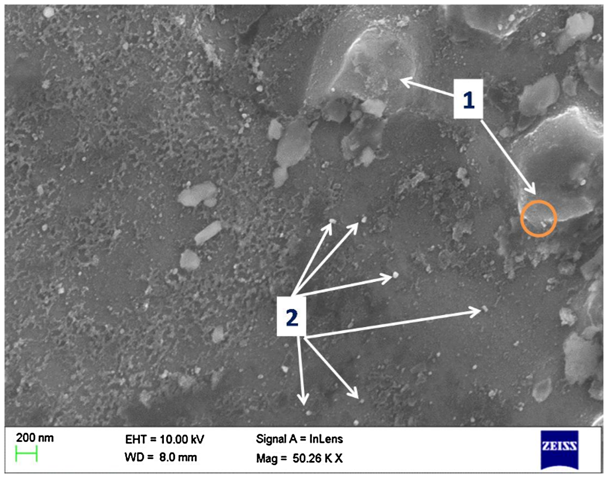
Figure 3 shows the SEM micrograph of AA 2219 + 2% n-B4C nanocomposites. There are no cluster zones of nano-B4C particles in the microstructure. Homogenous distribution of nanoparticles is very important in improving the mechanical and tribological properties. Dendritic solidified structures are not found in the microstructure. There are no observations of nanoparticle clusters in the microstructure. Equilibrium precipitates are also seen in the microstructure. The spot EDS on tiny particles confirms the presence of B4C, as seen in Fig. 4. The identification of Ti comes from the exothermic reaction of K2TiF6 salt with the B4C particles in the melt. The dissociation K2TiF6 flux during the reaction liberates K and F that remove the oxides from the matrix surface.23, 24 The heat generated by the exothermic reaction locally increases the temperature adjacent to the matrix/B4C particle interfaces.
10
The rise in temperature helps in more wetting of particles in the melt matrix and also assists in breaking up agglomerated nanoparticles.
19
The reaction also removes the thin oxide layer present around the particles and forms the very thin layer of Ti compound (TiB2 and TiC) around the particles by the following reaction.25, 26

Microstructure of 2219 + 2% n-B4C composites, Arrow shows the n-B4C particles, the circle is the region where EDS was taken. The EDS spectrum is reported in Fig. 4
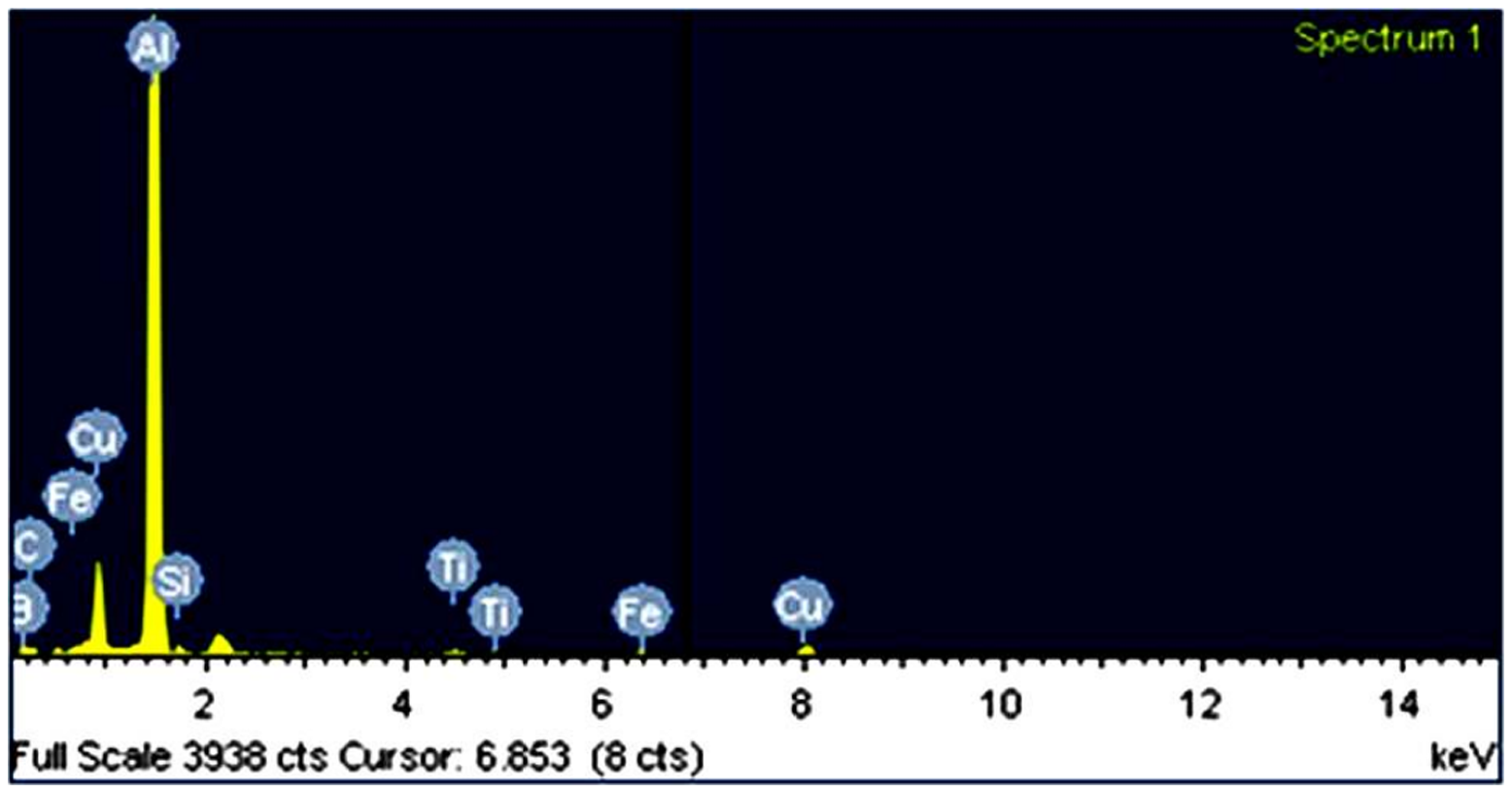
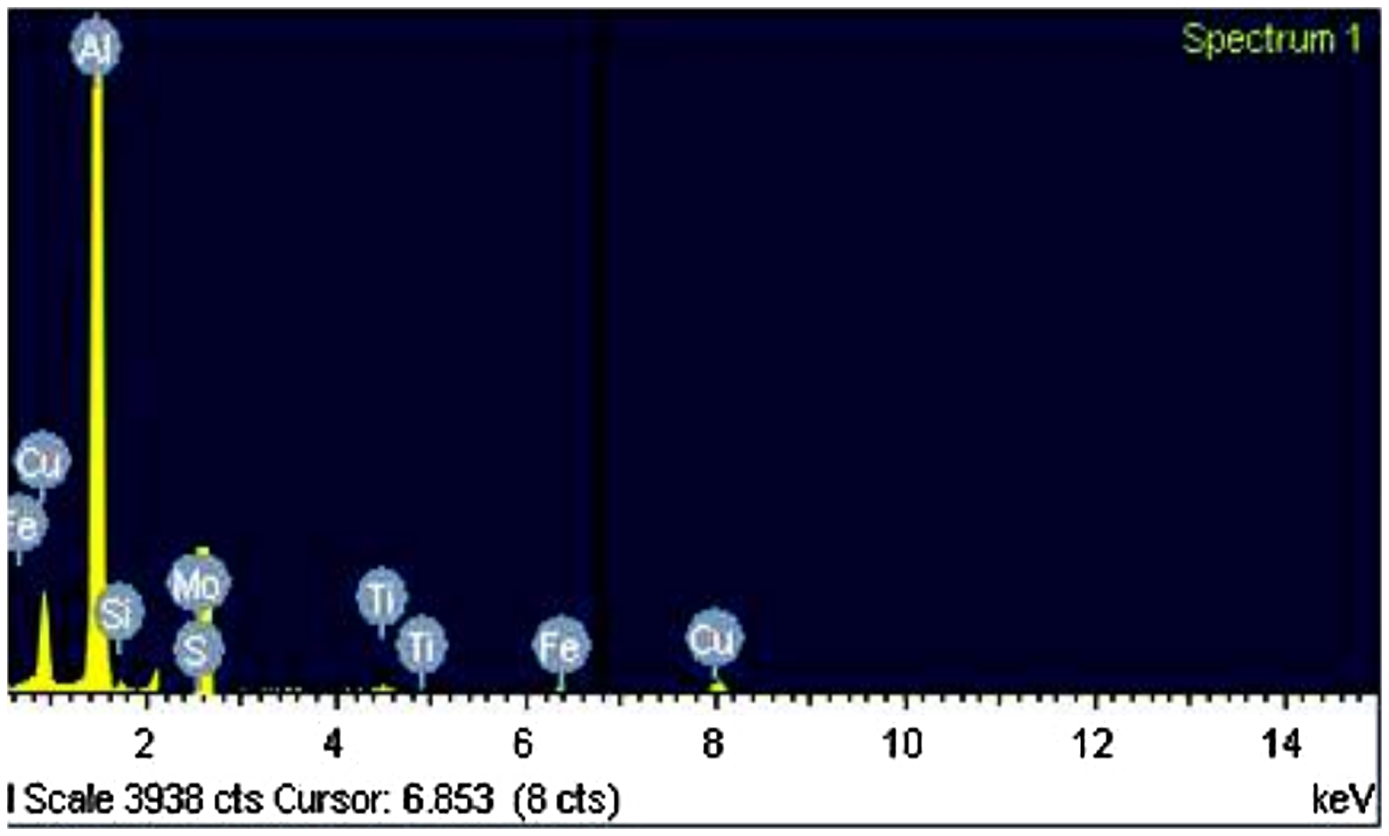
EDS spectrum showing the peaks of B, Ti and C (confirming the presence of B4C and thin layer of Ti compounds (TiB2 and TiC)) in the AA 2219 + 2% n-B4C composite
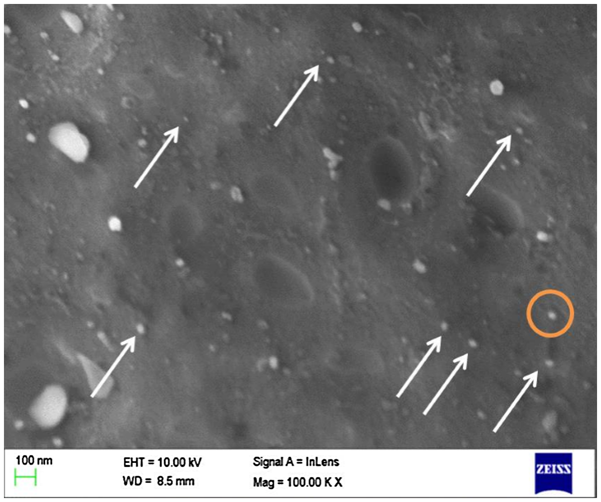
The identification of elements such as Ti, B and C in the EDS spectrum in Fig. 4 supports the above explanation. The formation of Ti compounds helps to improve the wettability of the B4C particles with the matrix.10, 11, 25 In addition, it prevents nanoparticle clustering and undesirable interface reaction between the Al matrix and B4C particles by acting as a strong barrier. 27 Thus, the nanoparticles are well bonded with the matrix. The studies by Kalaiselvan et al. 10 and Toptan et al. 25 showed the beneficial effects of K2TiF6 salt addition in improving the Al/B4C interface bonding. Fig. 5 presents the SEM micrograph of AA2219 + 2%n-B4C + 2%MoS2 nanocomposites. The particles (B4C and MoS2) are uniformly distributed in the Al matrix. The interfaces (matrix and MoS2 and matrix and B4C) are found to be clean and continuous without any porosity or cracks or discontinuity. The absence of contrast difference in Al/MoS2 interfaces indicates that there are no interface products at the interface. This result confirms that the selected stirring speed and other process parameters are optimum to obtain fairly uniform dispersion of particles in the matrix. The EDS examination, as shown in Fig. 6, confirms the presence of sub micron MoS2 particles in the matrix. Examination of the interface between Al matrix and MoS2 particles shows that the interfaces are continuous without any casting defects such as porosity and shrinkage.
Microstructure of AA2219–2% n-B4C-2% MoS2 composites, (1) MoS2 and (2) B4C particles, the circle is the region where EDS was taken. The EDS spectrum is reported in Fig. 6
EDS spectrum showing peaks of Mo and S (confirming the presence of MoS2) in AA 2219 + 2% n-B4C + 2%MoS2 composites
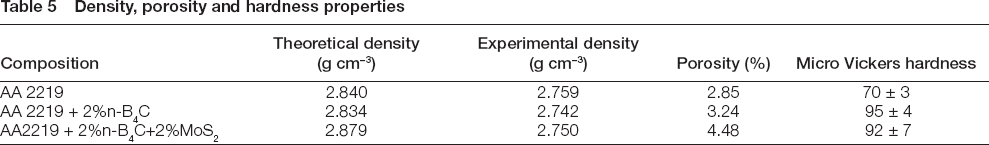
Density and hardness
Table 5 shows the density, porosity and Vickers micro hardness values of AA2219, AA 2219 + 2% n-B4C and AA2219 + 2% n-B4C + 2%MoS2 nanocomposites. The density of the composites decreases with the addition of B4C and increases with the addition of MoS2. The increase or decrease in the density of the composites is attributed to the respective particle density. Another important factor deciding the density is the porosities developed during solidification. It is important to note that the addition of B4C and/or MoS2 has a significant influence on the porosity fraction of the composites. Particle additions increase the porosity content in the composites, as seen in Table 5. This result agrees with the Akbari et al. work on A356/n-Al2O3 composites. 4 The porosities are usually found at the periphery of the samples as seen in Fig. 7. Differential cooling rate between the mould wall and the melt centre results in distribution of the pores in the periphery. Comparing the contribution of particle density and porosity to the density of the composites, the porosity is the most important factor deciding the density. This is clear from the results of hybrid composites, although these composites have denser MoS2 particles; the density is not significantly higher than the unhybrid Al/B4C composites. It is because of the large size MoS2 particles that induce more porosity at the interface through porosity associated with individual/small clustered particles. 28 Other stirring factors such as position of the stirrer and time, the trapped air between the particles contribute to the porosity development in the solidified melt. 4 The relatively higher amount of pores in the hybrid composite is attributed to the higher amount of particle fraction. Although the porosities are insidious to the mechanical properties, it is helpful in the sliding wear by acting as a path for the solid lubricant flow to the contact surface to form a thick tribolayer.
Density, porosity and hardness properties

a AA2219 alloy, b AA 2219 + 2% n-B4C and c AA2219 + 2% n-B4C + 2%MoS2 composites orientation images showing the porosity distribution
The hardness results show that the addition of nanosize B4C particles greatly increases the hardness. The presence of nanoparticles acts as a strong barrier for dislocations motion. As the size is in nanoscale, the interparticle spacing between them is much lesser. Thus, the pinning of dislocations is quite easy and as a result, the strength is increased significantly due to the rise in stress required to over loop or shear the particles. The nanoparticles provide strong plastic constraint effects to the matrix and work harden the matrix. The nanoparticles act as the nucleation sites for grain formation during solidification. As the interparticle spacing between nanoparticles is extremely small due to the nanosize range, the growing grains are pinned by the particles (Zener pinning) that lead to the evolution of fine size grains. Thus, fine grains enhance the strength of the composites through grain boundary strengthening (Hall-Petch strengthening). The increase in the grain boundary area is an effective obstacle to the dislocation motion. Further, the wide difference in thermal contraction behaviour of particles (coefficient of thermal expansion = 5 × 10⁻⁶/°C) and the matrix (coefficient of thermal expansion = 25 × 10−6/°C) generates a forest of dislocations at the interfaces of the matrix and particles by thermal stress relaxation. 19 Also, the difference in elastic modulus match between the matrix and particles (Taylor strengthening) increases the dislocation density. In summary, the dislocation forest strengthening, Taylor strengthening, Orowan dislocation strengthening and nanoparticle-assisted grain refinement are proposed to explain the increased hardness in the nanoparticle-reinforced MMCs.16, 29 Considering the error bar values, the MoS2 addition does not seem to decrease the hardness of the hybrid nanocomposites. The relatively high fluctuation in the hardness of hybrid composites is attributed to the high porosity content that increases the probability of indentation falling on the pores.
Wear behaviour
Effect of load
Figure 8 shows the variation in specific wear rate with applied loads at sliding velocity of 4.39 m s−1 and sliding distance of 1500 m. It is clear from the results that the nanocomposites show superior wear resistance than the base matrix alloy. These results correlate well with the high hardness values of nanocomposites. Between unhybrid and hybrid nanocomposites, the hybrid nanocomposites show significantly higher wear resistance due to the role MoS2 lubricants. The wear rate of both matrix alloy and nanocomposites increases with an increase in load. However, the slope of wear rate of the nanocomposites is shallower than the Al alloy. Particularly, the hybrid nanocomposites show very less increment in wear rate with increasing load. Although the unhybrid composites show lesser increment in wear rate than the Al alloy with an increase in load, the slope rises sharply above 50 N load. This indicates that the protection of the matrix by nanoparticles against surface shear ceases above 50 N load. In other words, the nanoparticles begin de-bonding from the matrix through interface cracking.
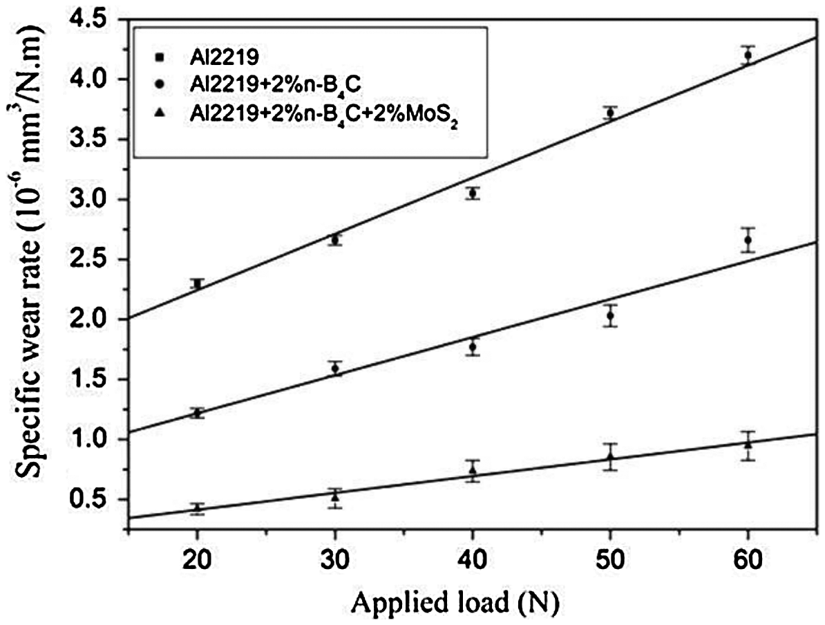
Variation of specific wear rate with load (sliding velocity: 4.39 m s−1, sliding distance: 1500 m)
The wear surface examination under SEM shows that the delamination wear mechanism has just begun in the wear surface of Al alloy for the 20 N load case as seen in Fig. 9a. Thus, the wear rate is significantly higher than the nanocomposites. These features suggest that the sub surface plastic deformation begins well below 20 N in the base Al alloys. At or below 20 N load, the cracks nucleated at the deformed sub surface preferably the equilibrium second phase particles, as the second phase particles are preferable sites for void formation in the plastic flow. 30 Further, as the second phase particles are big and widely spaced (interparticle spacing is large) in the alloy, the propagation of crack to the surface is easy leading to the removal of long wear sheets. The morphology of the loose debris confirms the long, massive and irregular shape as seen in Fig. 10. As the load increases, the delamination wear mechanism intensifies and accelerates the wear rate. The wear surface of Al alloy tested at 60 N shows several exfoliated (serrated) surface layers. The observation of a rough surface with the flow lines and flaky morphology is the indication of strong delamination wear as seen in Fig. 9b.
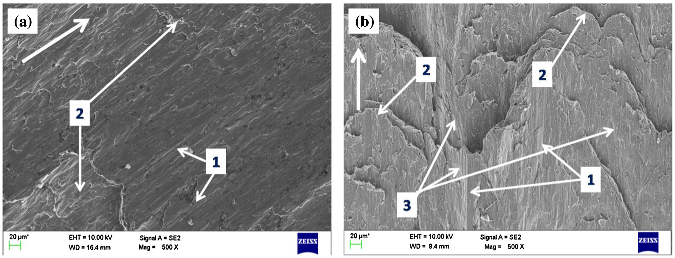
Worn out surfaces of AA 2219 alloy tested for the conditions of a sliding velocity of 4.39 m s−1 and sliding distance 1500 m at a 20 N, b 60 N load respectively, (1) abrasive grooves, (2) delaminated wear sheets and (3) irregular flow lines. Arrow shows the direction of sliding
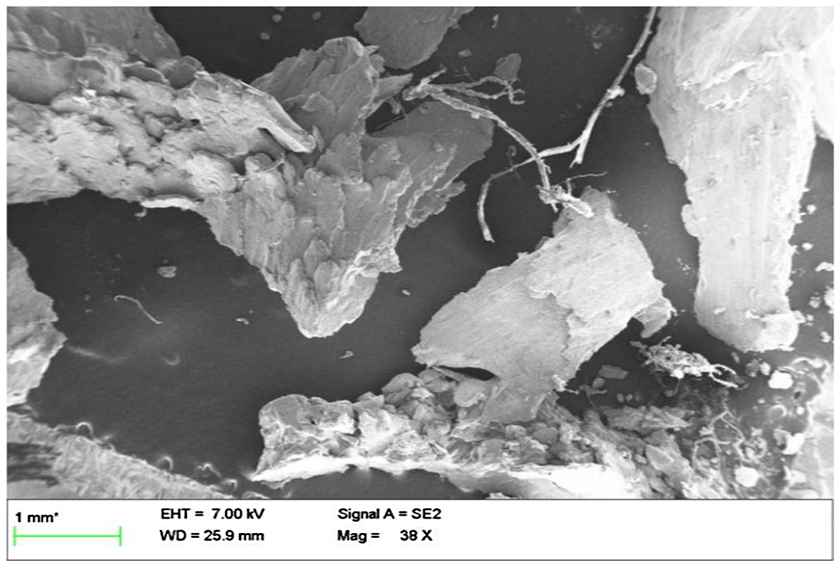
SEM image of loose wear debris of AA2219 matrix tested for the conditions of a sliding velocity of 4.39 m s−1, load of 60 N and sliding distance 1500 m
The wear surface of the unhybrid nano B4C-reinforced composites tested at 20 N shows thin, widely spaced abrasive grooves, as seen in Fig. 11a. The grooves are formed by the microcutting of the counter surface steel asperities. 2 The asperities are sharp and tiny in nature. Hence, the load carried by asperities is higher than the applied load. The asperities plow the surface and remove the material as a thin, micron size regular shape particles, as seen in Fig. 12a. In addition, loose wear debris trapped between the contact-couple assists in the groove formation by ploughing effects. The increase in load gives more local stress to the composite through asperities and accelerates the abrasive wear by forming deeper grooves. The absence of delamination wear features indicates that the load is insufficient to cause the strain gradient in the sub surface to initiate plastic flow. The presence of nanosize B4C is attributed to the strengthening of the composites. The nanoparticles reduce the interparticle spacing and act as a strong barrier for dislocation motion. The elastic modulus mismatch and coefficient of thermal expansion mismatch generate geometrically necessary dislocations in the matrix and particle/matrix interfaces and enhance the dislocation density significantly.16, 29 The interaction of the forest of dislocations under the contact load strength the sub surface by the work hardening effects sense.16, 29 The strengthening by nanoparticles helps to sustain the contact load of 20 N. As the load increases, the dislocations move past the particles by Orowan over looping mechanisms. Thus, the matrix strengthening by nanoparticles enhances the load bearing ability of the composites. From the wear results, it may be guessed that the sub surface plastic flow is accelerated above 40 N. It may be probable that the pile-up dislocations at the grain boundary and nanoparticles in the sub surface raise the stress concentration above the fracture stress of the matrix. This initiates a delamination crack at the particle/matrix interface through shear deformation at the sub surface. The wear surface morphology of the sample tested at 60 N shows the significant delamination wear features with thick abrasive grooves. These features suggest that mixed mode wear mechanisms with the strong effects of delamination wear prevail above 50 N load.
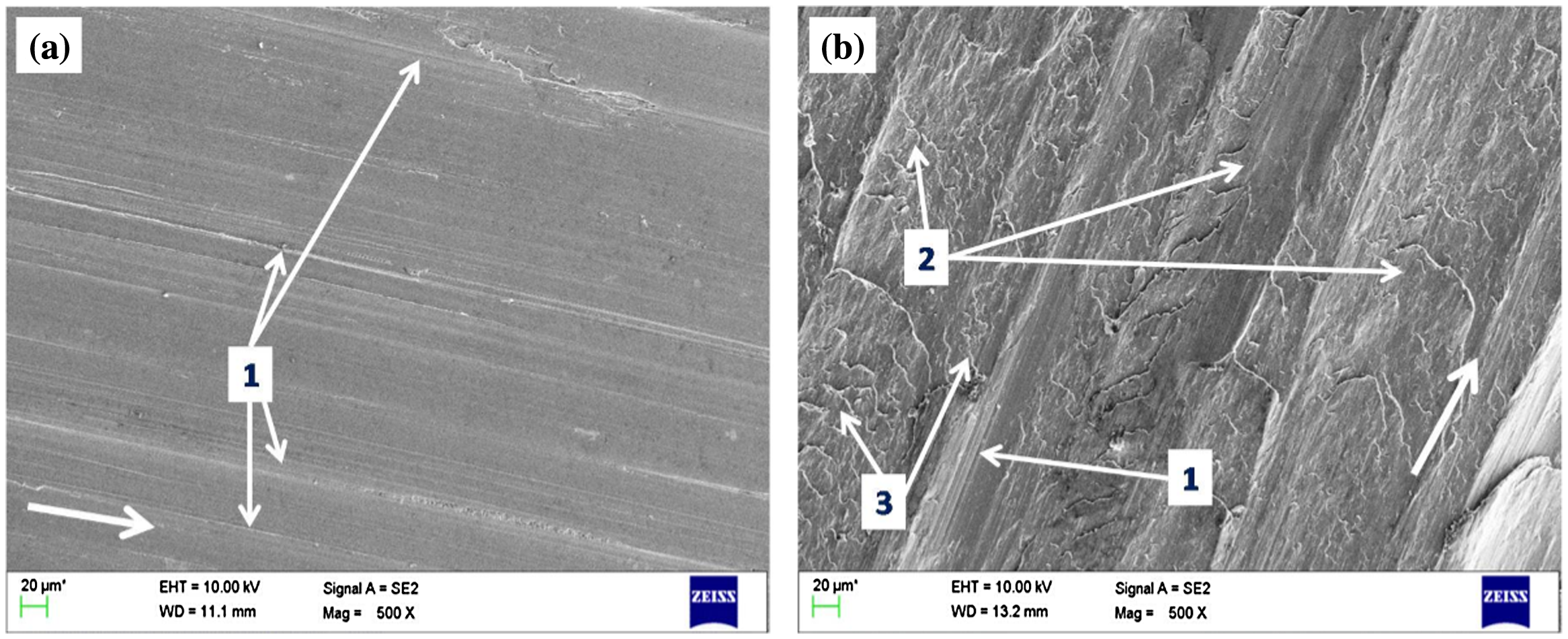
Worn out surfaces of the AA 2219/2% n-B4C composite tested for the conditions of a sliding velocity of 4.39 m s−1 and sliding distance 1500 m at a 20 N, b 60 N load respectively, (1) abrasive grooves, (2) delaminated wear sheets and (3) irregular flow lines. Arrow shows the direction of sliding
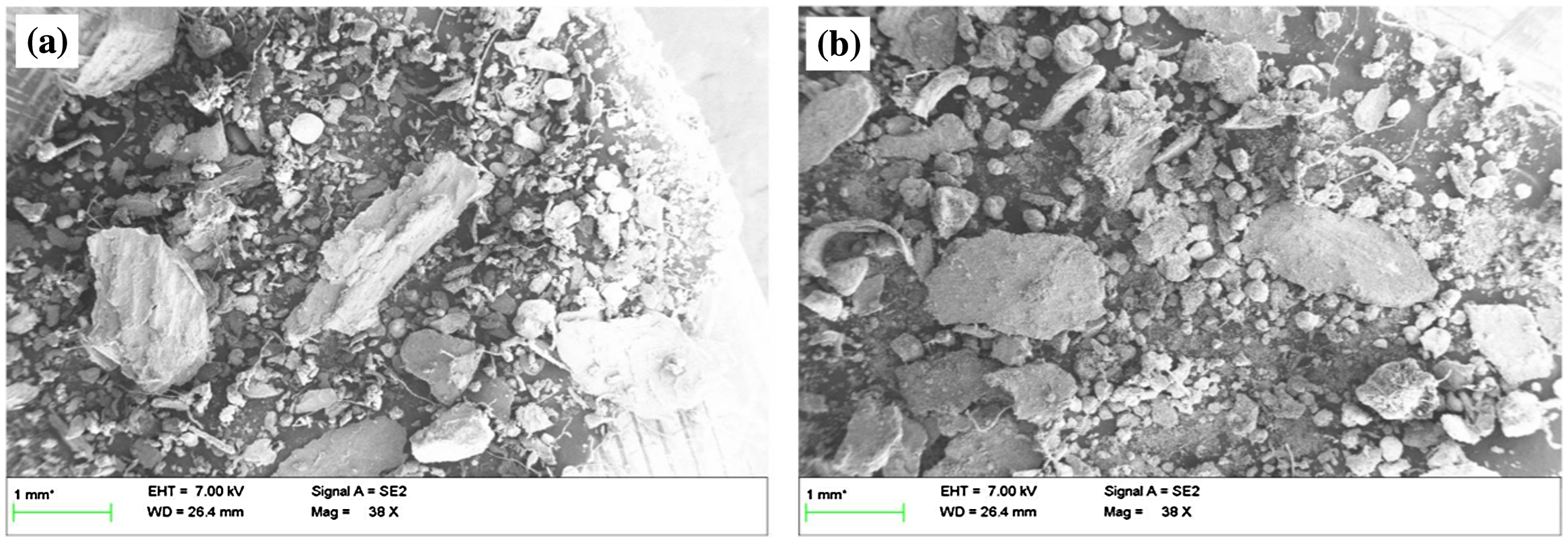
SEM images of loose wear debris of a Al2219 + 2%n-B4C, b Al2219 + 2% n-B4C + 2% MoS2 for the conditions of a sliding velocity of 4.39 m s−1, load of 60 N and sliding distance 1500 m
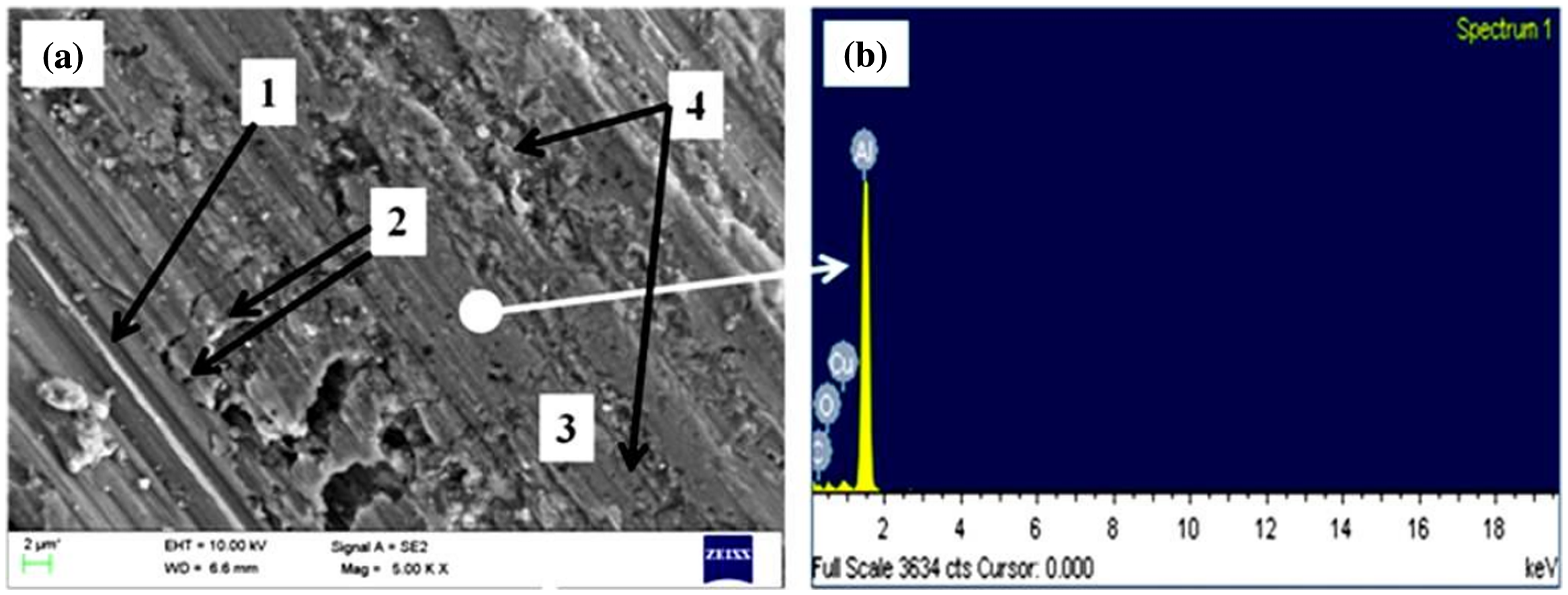
The wear rate of the hybrid composites is not affected significantly by the increase in load. The presence of MoS2 is primarily responsible for the sustainment of the wear resistance even when the contact load is raised. The MoS2 lubricant flows easily under the low contact load and squeezes out to the surface. This phenomenon is accelerated with an increase in load. The even spreading MoS2 on the surface forms the thick and continuous tribofilm that protects the substrate from the counter surface contact and hard loose wear debris entrapped between the contact couples. Further, this film replaces metal–metal asperities interlocking with nonmetal (tribofilm)–metal interlocking at the interface. The easy shearing of tribofilm under load helps to reduce the wear loss. The worn out tribofilm covers the hard loose wear debris by compaction during sliding under the applied load. The hard loose asperities form a tribolayer film around them. This film reduces the impact of micro cutting/scratching assisted wear especially at high load conditions. Thus, the wear rate is controlled with the addition of MoS2. The observation of grooves parallel to the sliding direction on the wear surface of the hybrid composite tested at 20 N, as shown in Fig. 13a, shows that abrasive wear is the dominant wear mechanism. Further, there are no signs of delamination wear on the wear surface. These observations are similar to that of unhybrid composites. The wear surface of the sample tested at 60 N shows mainly shallow delamination wear features. The tribofilm is clearly seen in Fig. 13b. The EDS composition profile identifies the Mo and S on the surface, as seen in Fig. 14. The extent of delamination is relatively much lesser than the one observed for unhybrid composites, as seen in Fig. 11b. The tribofilm stability is improved with the applied load due to the easy squeezing out and thick layer formation. This is the main reason for the improved wear resistance of the hybrid composites at high contact loads. The loose wear debris collected from the hybrid composite resembles similar to that of unhybrid composites is clearly seen in Fig. 12b. However, the amount of fine size regular shape debris is more for the case of hybrid composites indicating less wear loss.
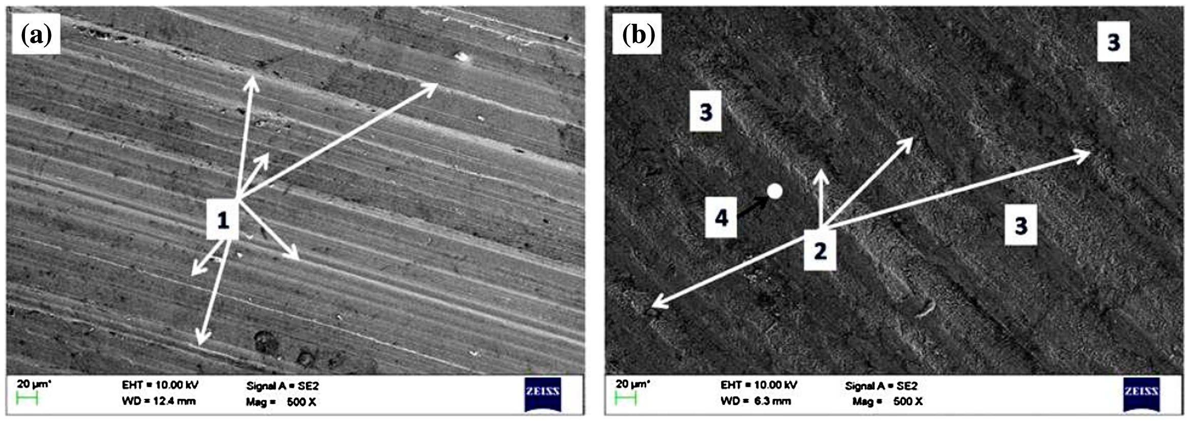
Worn out surfaces of the AA 2219 /2% n-B4C/2%MoS2 composite tested for the conditions of a sliding velocity of 4.39 m s−1 and sliding distance 1500 m at a 20 N, b 60 N load respectively, (1) abrasive grooves, (2) slight delaminated regions, (3) tribofilm and (4) the circle is the tribofilm region where EDS was taken. The EDS spectrum is reported in Fig. 14. Arrow shows the direction of sliding
EDS spectrum of tribofilm in the AA 2219 /2% n-B4C/2%MoS2 composites
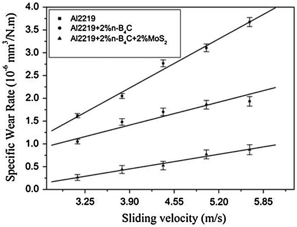
Effect of sliding velocity
Figure 15 presents the effects of sliding speed on the specific wear rate of the alloy and nanocomposites at 40 N load and 1500 m sliding distance condition. Our results are in agreement with other works on nanoparticle-reinforced Al composites. 31 The wear rate of the alloy increases with an increase in speed. As the speed increases, the friction-induced temperature at the interface rises that result in the softening of the surface and sub surface of the wear surface. The absence of matrix strengthening particles in the Al alloy accelerates the softening effects with the increasing sliding speed.
Variation of specific wear rate with the sliding velocity (Applied load: 40 N, sliding distance: 1500)
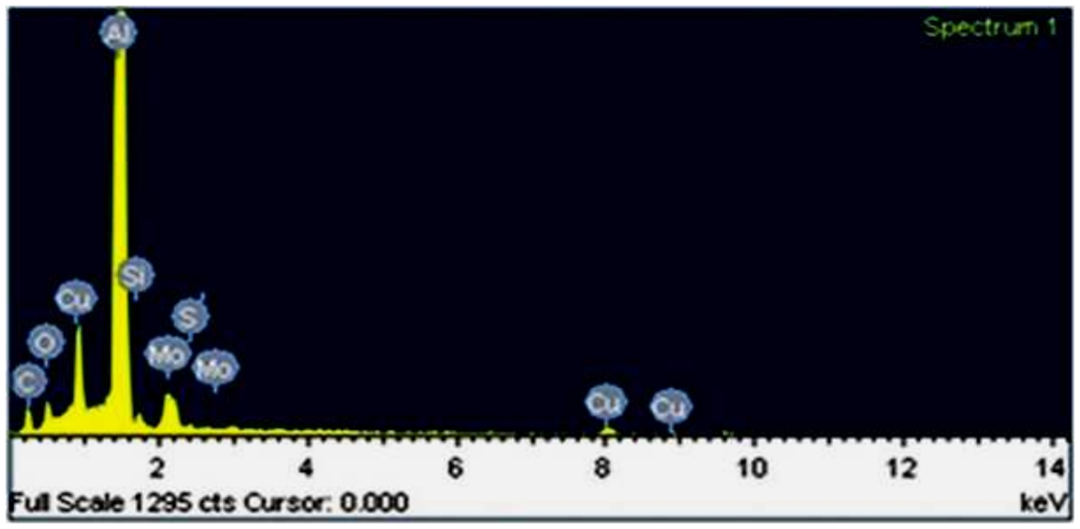
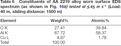
The wear surface of the alloy, as shown in Fig. 16a, shows the deep grooves and flecks. The grooves suggest the strong abrasive wear by counter surface asperities. The flecks are the sign of adhesive wear due to the metal (Al) to metal (steel) contact. The surface cracking perpendicular to the sliding direction is the sign of delamination wear. 31 The observation of O2 peak on the EDS image, as shown in Fig. 16b and Table 6, shows that the matrix has oxidised significantly. The friction reducing tribofilm does not form on the Al alloy surface due to the absence of solid lubricants. Thus, surface oxidation is not disrupted. The oxidation rate is accelerated with an increase in speed due to rapid removal of oxide scales and subsequent direct metal to metal contact for fresh oxidation. Another important fact is to note that the EDS spectrum does not show the presence of Fe peak on the wear surface. This indicates that the material from counter surface steel disc has not transferred to the wear surface and the absence of tribolayer at the interface. The controlled counter surface material transfer especially Fe is beneficial because the iron forms iron oxide (Fe3O4) at high sliding speed. The Fe3O4 has lubricating properties that helps in minimising the wear loss by protecting the pin surface especially at high sliding speeds. In summary, the rapid rise of wear rate with an increase in sliding speed is explained through strong effects of oxidation, delamination, adhesive and abrasive wear mechanisms in base Al alloy.
a Wear surface of the alloy tested at 5.65 m s−1 (Load: 40 N, sliding distance: 1500 m), b EDS spectra of the wear surface. (1) Deep abrasive grooves, (2) surface cracking, (3) flecks and (4) rough surface
Constituents of AA 2219 alloy worn surface EDS spectrum (as shown in Fig. 16b) tested at 5.65 m s−1 (Load: 40 m, sliding distance: 1500 m)
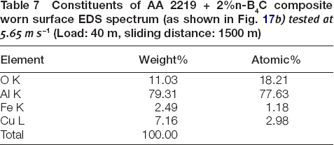
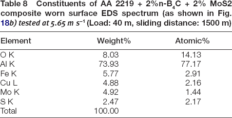
The wear rate of both unhybrid and hybrid nanocomposites increases initially with the sliding speed and saturates at above 5.02 m s−1. The initial sharp increase in wear rate up to 3.76 m s−1 is attributed to the abrasive cutting of the matrix and debonding of particles by the asperities from the countersurface and the loose wear debris. Compared to the Al alloy, the nanocomposites show improved wear resistance. The addition of nanoparticles enhances the matrix strength. Also, it minimises the adhesive wear prone matrix contacts with the counter surface. Thus, the effects of delamination and adhesive wear are lessened. The thermal stability of the nanocomposites is improved by the nano-B4C particles. Thus, the ill-effects of temperature on the composite matrix are minimised. Uthayakumar et al. 32 observed the boron oxide layer formation in the Al/B4C/SiC composites that assists in controlling wear resistance. The surface of the unhybrid nanocomposite is rough with abrasive grooves and surface cracks as seen in Fig. 17a. The ductile tearing of the matrix and the delamination wear result in surface cracking. In contrast, the surface of the hybrid composite is smooth with less groove lines, as seen in Fig. 18a. The tribofilm is seen as a dark grey scale on the surface in Fig. 18a. The EDS images of both unhybrid and hybrid nanocomposites, as shown in Figs. 17b and 18b, respectively, show the peaks of O2 and Fe. The elemental quantification of EDS spectrums is given in Tables 7 and 8, respectively, for unhybrid and hybrid nanocomposites. These peaks are the signs of occurrence of surface oxidation and the counter surface material transfer. This confirms the co-occurrence of oxidation wear along with other wear mechanisms in the composites. Comparing the unhybrid composite with the hybrid composite, the hybrid composites show better wear resistance. The presence of friction controlling tribofilm is primarily attributed to the better wear resistance. The film is enriched with a reasonable amount of MoS2 lubricants, as seen in Fig. 18b that protects the composite surface. The shearing of the MoS2 containing tribofilm reduces the friction at the contact surface. In addition, it controls the oxidation rate by acting as a barrier to the composite surface, as seen from the element quantification reported in Table 8. Another important point is to note that the friction-induced temperature has not crossed the decomposition temperature of MoS2 in the present study.
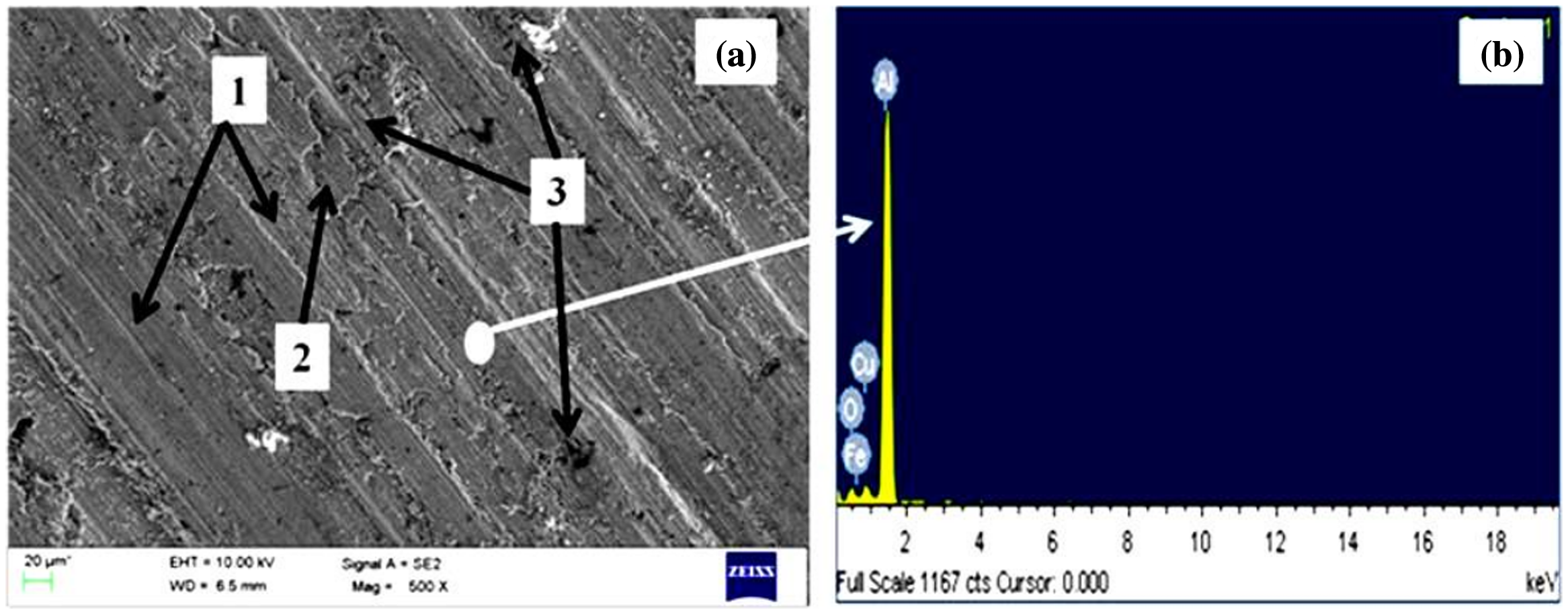
a Wear surface of the unhybrid nanocomposite (Al/n-B4C) tested at 5.65 m s−1 (Load: 40 m, sliding distance: 1500 m), b EDS spectra of the wear surface. (1) abrasive grooves, (2) surface cracking, and (3) rough surface
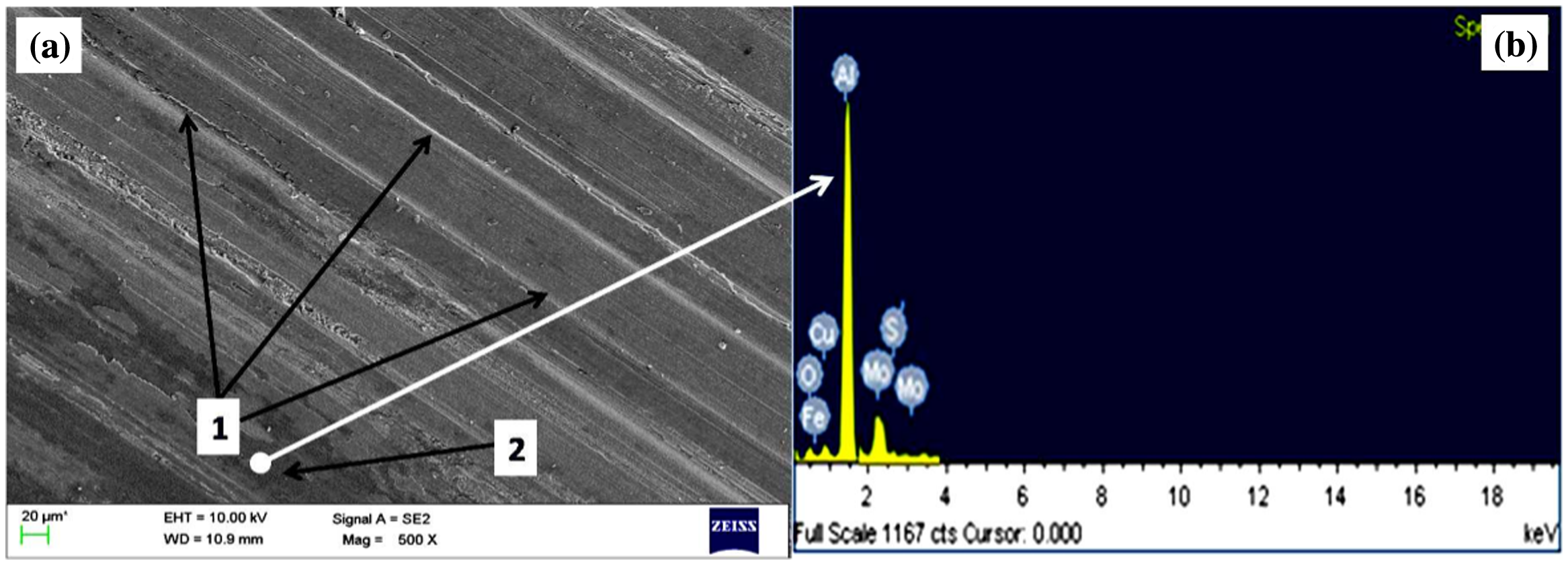
a Wear surface of the hybrid nanocomposite (Al/n-B4C/MoS2) tested at 5.65 m s−1 (Load: 40 m, sliding distance: 1500 m), b EDS spectra of the wear surface. (1) abrasive grooves and (2) tribolayer
Constituents of AA 2219 + 2%n-B4C composite worn surface EDS spectrum (as shown in Fig. 17b) tested at 5.65 m s−1 (Load: 40 m, sliding distance: 1500 m)
Constituents of AA 2219 + 2%n-B4C + 2% MoS2 composite worn surface EDS spectrum (as shown in Fig. 18b) tested at 5.65 m s−1 (Load: 40 m, sliding distance: 1500 m)
Effect of sliding distance
The effects of sliding distance on the specific wear rate of the alloy and composites for the load and speed conditions of 40 N and 4.39 m s−1, respectively are shown in Fig. 19.
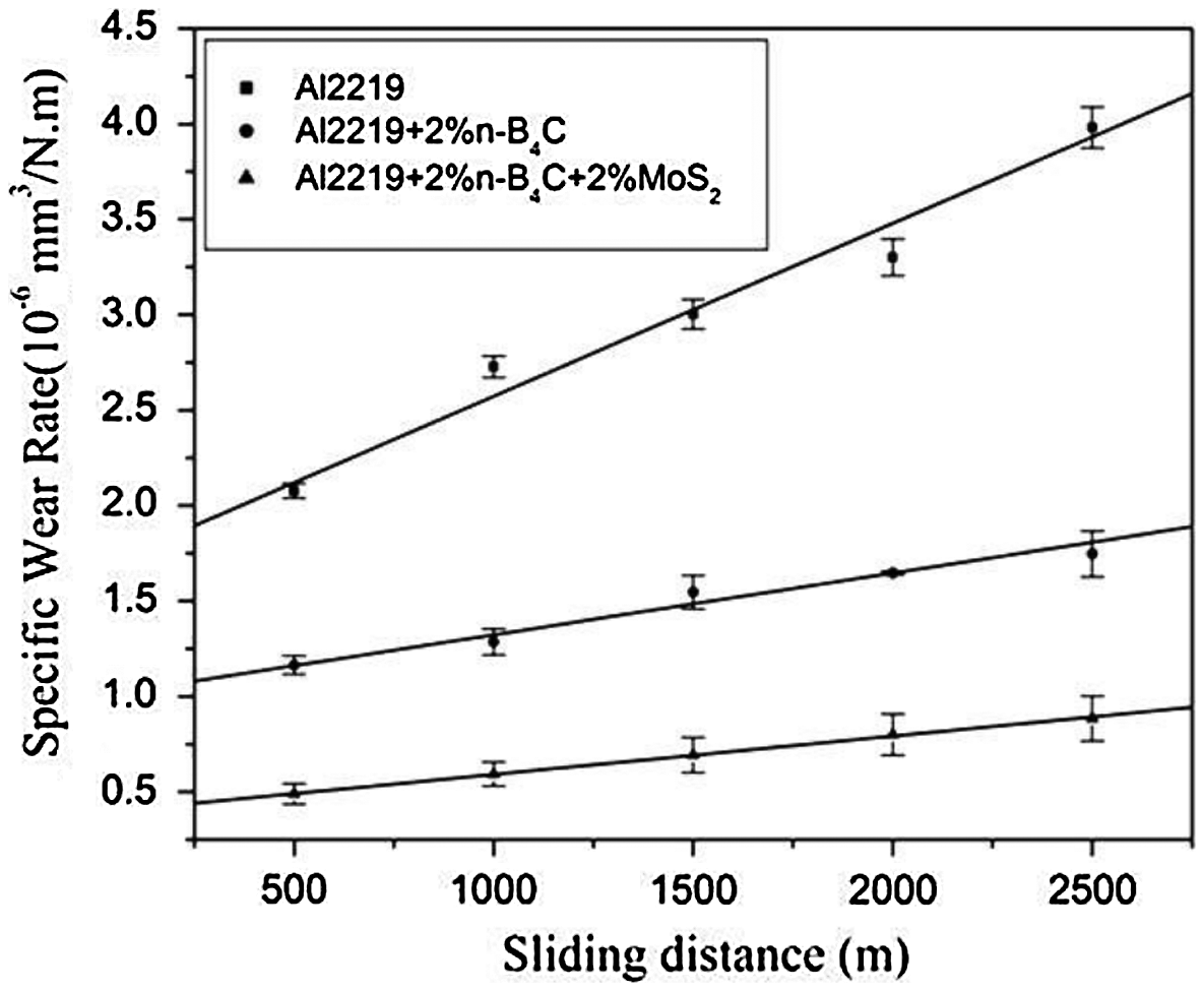
Variation of specific wear rate with sliding distances (Applied load: 40 N, sliding velocity 4.39 m s−1)
The wear rate of the alloy rises with the sliding speed significantly. The wear rate rises sharply above 2000 m. This is mainly by third body wear assisted by loose wear debris. As can be seen in the worn surface (Fig. 20a and b), there are many sharp, lengthy burrs formed by ploughing of counter surface asperities. 4 These burrs are work hardened materials. These burrs when detached from the worn surface become hard, abrasive loose wear debris. The debris acts as a ploughing agent under the contact force and accelerate the wear rate of the alloy significantly. This effect is intensified with the increasing load and/or sliding speed. In contrast, the nanocomposites show marginal increase in wear rate with the sliding distance. The relatively smooth surface, as seen in Fig. 20c and d, in nanocomposites corroborates the above results. Particularly, the hybrid composites show least wear rate indicating the tribolayer controlled wear. The wear debris gets covered with the loose solid lubricant during sliding and blunts the ploughing effects of debris by lubrication. These results show that the sliding distance does not affect much the wear rate of the nanocomposites.
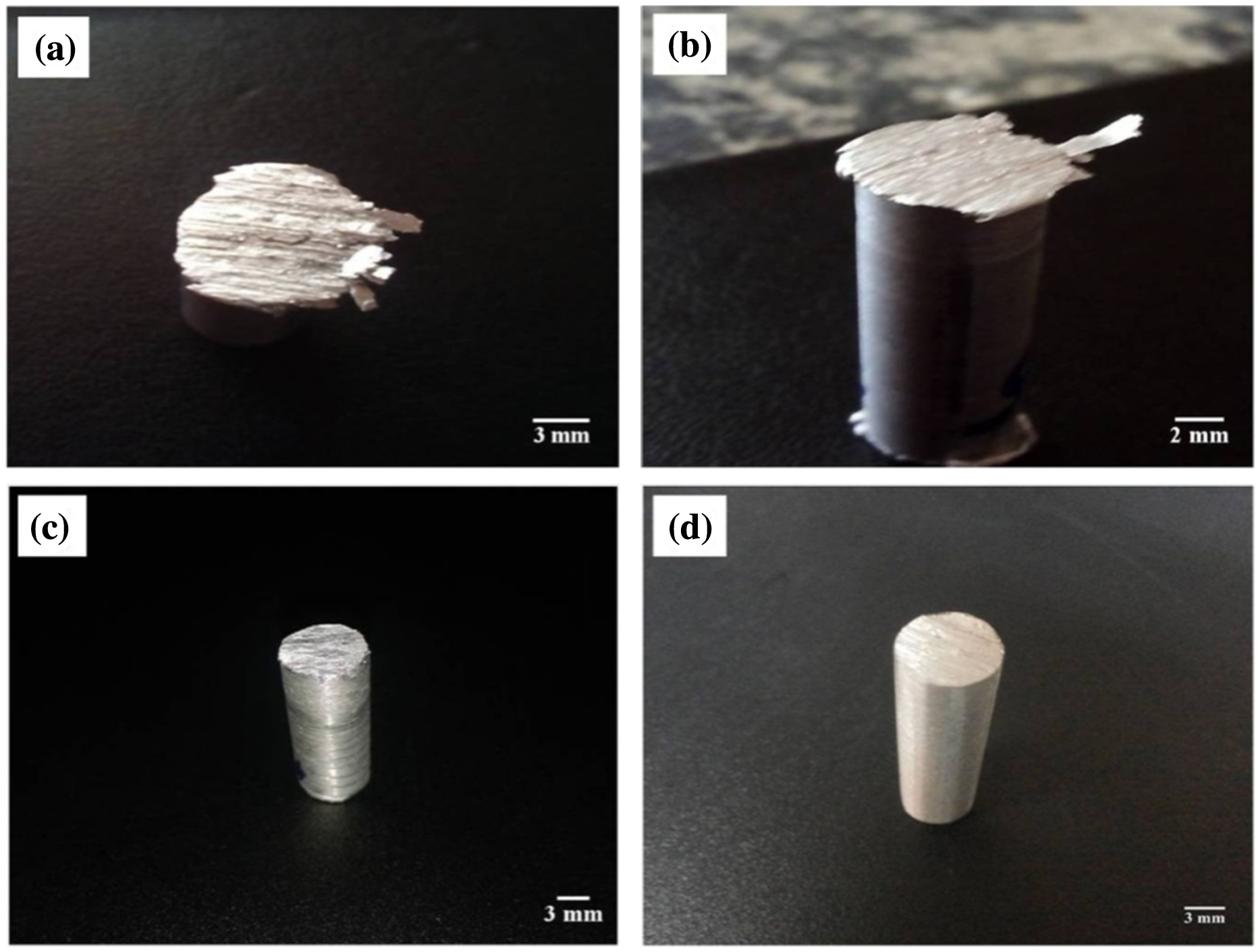
Digital photographs of material extrusion and burr formation on the edge of pin a AA 2219 at a load 60 N, at the sliding velocity 4.39 m s−1 and sliding distance 1500 m, b AA2219 at a load 40 N, at the sliding velocity 4.39 m s−1 and sliding distance 2500 m, c AA 2219 + 2%B4C at a load 40 N, at the sliding velocity 4.39 m s−1 and sliding distance 2500 m, d AA2219 + 2%B4C + 2%MoS2 at a load 40 N, at the sliding velocity 4.39 m s−1 and sliding distance 2500 m
Conclusions
The nanosize B4C particle-reinforced composites with and without MoS2 hybridisation was processed through stir casting and compared with the base alloy (AA 2219). The key findings of the present work are:
The exothermic reaction between B4C and K2TiF6 flux provides a thin layer of Ti compounds around the particles. This layer improves the wettability of B4C with the Al matrix and also acts as a strong barrier for nanoparticle clustering. The density of the composites decreases with the addition of B4C and increases with the addition of MoS2. The influence of porosity fraction is higher than the particle density in deciding the density of the nanocomposites. The addition of nano B4C significantly increases the hardness of the Al alloy. The mechanisms such as dislocation forest strengthening, Taylor strengthening, Orowan dislocation strengthening and nanoparticle-assisted grain refinement are responsible for the hardening of the nanocomposites. The addition of 2% soft MoS2 has a marginal influence in decreasing the hardness of the nanocomposites. The wear resistance of the nanocomposites is much higher than the base alloy at all load, sliding speed and sliding distance conditions. Between nanocomposites, the MoS2 hybridised composite shows improved wear resistance than the unhybridised composite for all load, sliding speed and sliding distance conditions. The formation of lubricant rich tribolayer in hybrid composites adds wear resistance improvement in addition to nanoparticle strengthening effects. The wear rate of the nanocomposites and the base alloy increases with the increase in load, speed and distance. The rate of increase depends on the presence of nanoparticles and solid lubricants. The critical load to initiate delamination wear in unhybrid and hybrid nanocomposites is roughly around 40 and 60 N, respectively. Below this load, the wear occurs mainly by abrasive wear. At or above this load condition, the features of mixed mode (delamination, abrasive, tribofilm assisted and oxidation) wear mechanisms are observed. The intensity of oxidation wear increased with the increase in sliding speed. The counter surface material transfer is clearly observed for nanocomposites, whereas it is absent in Al alloy wear. The effects of third body loose wear debris are relatively less with the increase in sliding distance due to the lubricant-rich tribofilm controlled wear in hybrid nanocomposites.
Funding
This work was supported by the World Bank Assisted TEQIP Phase-II for Research Assistantship.
Footnotes
Acknowledgements
Siddesh Kumar and Shiva Shankar wish to express their gratitude to his holiness Dr. Sri Sri Shiva kumara Swamigalu president, SSES, S S Mutt. Siddesh Kumar and Shiva Shankar would like to thank Principal- Dr. Shivakumaraiah and Director- Dr. M.N. Channabasappa, Siddaganga Institute of Technology, Tumkur, Karnataka, India, for providing the facilities to carry out research work in Department of Mechanical Engineering. The first author1 also would like to acknowledge doctoral committee member Dr. N.H. Siddalingswamy, Director, E-Governance, AICTE, New Delhi, for their suggestions on this work. The first author would like to thank the management of Siddaganga Institute of Technology, Tumkur, Karnataka, India, for financial support under World Bank Assisted TEQIP Phase-II for Research Assistantship.