
Abstract
Aluminium (AA5083)-alumina surface composites are prepared by friction stir processing in two conditions of heat input. The low heat (LH) input conditions is achieved at a rotational speed of 710 rpm and a traverse speed of 100 mm/min, and high heat (HH) input conditions are achieved at a rotational speed of 1400 rpm and a traverse speed of 40 mm/min. The tribological characteristics of aluminium alloy, friction stir processed (FSPed) alloy and FSPed surface composites against steel ball are studied at 5, 10 and 20 N load. While no significant influence is found on frictional behaviour, wear resistance of FSPed composites is superior to FSPed alloys. FSPed composites fabricated at HH input conditions exhibited improved wear resistance as compared to LH input condition. Adhesion and delamination are dominant wear mechanisms at 20 N. Debris particles are reduced in size and hydroxidated in sliding of surface composites.
Introduction
Wear mechanisms of metal matrix composites are known to be governed by several factors in a sliding wear system. Hard ceramic particle reinforcement plays a dominating role but formation and stability of mechanically mixed layer, humidity and counter body are also effective parameters in influencing wear mechanisms [1,2]. Surface composites are suitable materials in engineering applications where surface contact is involved. In such applications, the useful life of component mainly depends on the surface properties like hardness and wear resistance. Therefore, it is highly desirable that the surface of the component exhibits desired hardness while the substrate still maintains the original structure with good ductility and toughness [3,4].
Aluminium alloys are extensively used in engineering applications owing to high strength-to-weight ratio, good formability and resistance to corrosion [4]. However, low hardness limits their applicability for tribological applications. To enhance the performance in tribological conditions, ceramic particles are reinforced in aluminium alloys [5,6]. Al–Mg-based alloys and in particular AA 5083 alloy is widely used for automobile, transportation and marine applications due to excellent corrosion resistance, good weldability, high strength and formability [4,5].
There are varieties of techniques such as liquid melt stirring, powder metallurgy, etc. for ceramic particle reinforcement in aluminium alloys [6–8]. Friction stir processing (FSP) is relatively a new route for particle reinforcement on the surface of metal and alloys in solid state condition [3]. FSP consists of plunging of rotating cylindrical tool having co-axial probe into the matrix material and moving in the desired direction. This technique causes intense plastic deformation in the processed material leading to grain refinement by dynamic recrystallization [9,10].
In FSP, a combination of rotational and traverse speed of tool determines the amount of heat input (HI) in the processed zone. Lower rotational speed provides lesser amount of heat and low traverse speed increases the duration of high-temperature exposure. It is evident from the literature that rotational speed is more effective on stirred zone than traverse speed. With the increase of rotational speed, the peak temperature is increased [9–11]. Higher rotational speed is required for distribution and breaking up of clusters of reinforcement particles. However, high rotational speed affects grain refinement due to high heat (HH) input. Thus, rotational and traverse speed must be optimized to achieve a defect-free SZ and reduced grain size [12].
HI influences the material flow and microstructural evolution in the processed zone, which directly affects the mechanical and tribological properties. The HI index using processing parameters of rotational (ω) and traverse (ν) speeds have been proposed as per the following relationship given in Equations (1) and %(2) [9].
Surface composites are fabricated by matrix material with various reinforcement particles such as Al2O3, SiC, ZrSiO4, SiO2 and B4C in micron or nano size [6,7,11–13]. The alumina particles are widely used reinforcement in aluminium alloys due to thermal stability and cost-effectiveness [6,11,12]. Tang et al. [13] studied the wear behaviour of boron carbide (B4C) reinforced AA5083 alloy matrix composite fabricated with a powder cryomilling and consolidating process. It was observed that the wear rate of composite reinforced with 10 wt-% B4C was approximately 40% lower than that of a composite containing 5 wt-% B4C. Hosseini et al. [14] utilized solid-state processing route of continual annealing and roll bonding process to fabricate silicon carbide (SiC) reinforced AA5083 alloy composite. The mechanical properties of the composites were enhanced by uniform dispersion of reinforcement particles. Soleymani et al. [15] fabricated surface composites by reinforcing molybdenum disulphide and SiC particles in AA5083 alloy via FSP route. They observed that hybrid composites showed the highest wear resistance due to the formation of the solid lubricating film. Behnagh et al. [16] found that the coefficient of friction in FSPed AA5083 alloy is nearly half as compared to the base alloy due to increase in hardness after FSP.
The literature study indicates that the effect of HI conditions in FSP of AA5083 alloy surface composites on tribological behaviour is not systematically investigated. In the present work, two combinations of rotational speed and transverse speed are used to obtain low heat (LH) input and HH input conditions in FSP to fabricate AA5083-alumina surface composites. The microstructural and mechanical characteristics of FSPed composites are studied. The effect of HI on the mechanical and sliding wear properties of base aluminium alloy, FSPed aluminium alloy and FSPed aluminium alloy surface composite is systematically investigated at three different loads (5, 10 and 20 N) against steel. Wear mechanisms are elucidated as a function of FSP and sliding wear test parameters.
In this work, 6.35 mm plates of commercially available aluminium 5083 alloy (Mg 4.1, Mn 0.5, Si 0.4, Fe 0.4, Zn 0.25, Ti 0.15, Cu 0.1, Al balance in wt-%) and alumina powder (Al2O3) of average particle size ∼75 μm were used to fabricate surface composites by FSP route. The Al2O3 particles were placed in the blind hole of 2 mm diameter and 2 mm depth drilled with 1 mm spacing in an aluminium plate. The estimated volume fraction of the reinforcement particles in the stir zone was nearly 0.12. The vertical milling machine with a fixture attachment to hold the plate was used for FSP. The schematic of FSP for fabrication of surface composites is shown in Figure 1. A non-consumable H13 steel tool (∼55 HRC) with a square pin of 4 mm length and 5 mm diagonal and concave shoulder of 18 mm diameter was used to process the plates filled with particles. Four pass FSP was applied by 100% overlapping with changing direction of tool rotation after each pass. A tool tilt angle of 2.5° was used and plate was allowed to cool at room temperature before each pass. The FSP of the plates was carried out using two combinations of rotation and traverse speeds: (i) 710 rpm–100 mm/min, and (ii) 1400 rpm–40 mm/min. The first combination provides LH input and the second provides HH input. A K-type thermocouple was inserted in the centre of plate at 2 mm below the tool probe tip to measure the maximum temperature generated during processing.
Schematic illustration of FSP for fabrication of surface composites.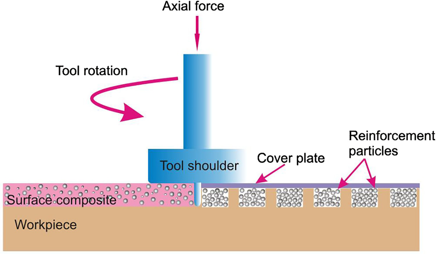
Microstructures of alloys and composites were studied using a LEICA DMI 5000M optical microscope. Specimens for metallographic examination were cut normal to the processing direction and prepared using a standard grinding and polishing technique to obtain a surface finish with an average roughness (Ra) of 0.1 μm. Etching was done using modified Poulton's reagent (30 mL HCl, 40 mL HNO3, 2.5 mL HF, 12 g CrO3, 42.5 mL H2O). The hardness tests were performed using a Vickers microhardness tester (Omnitech MVH-11, Pune, India) by employing a 200 gf load for 15 s.
Sliding wear tests were conducted using a ball-on disc tribometer (TR-201E-M2, DUCOM Instruments, Bengaluru, India) in ambient laboratory conditions of 25 ± 5°C and 60 ± 5% RH. The schematic of the ball-on-disc experimental set-up is shown in Figure 2. A commercially available AISI 52100 steel ball (∼60 HRC) of 6 mm diameter slides on the sample of 18 × 12 × 6 mm attached to the disc by means of screws provided in the attachment.
Schematic of ball-on-disc wear test set up.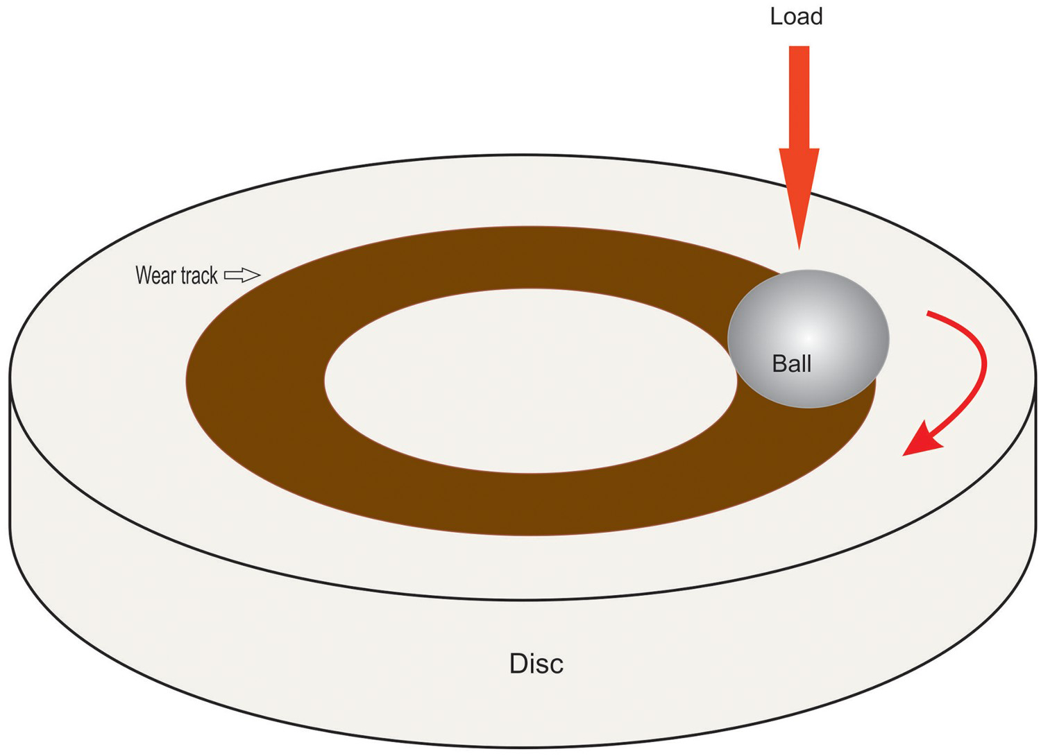
Both steel balls and disc samples were ultrasonically cleaned with acetone prior to wear testing. Steel balls were fixed in the ball holder so as to make a track radius of 1.5 mm from the central axis and tests were conducted at a fixed rotational speed of 500 rpm (linear speed of 0.0785 m/s) for 25 min (total sliding distance of 117.75 m). The sliding tests were carried out at 5, 10 and 20 N load that resulted in a maximum Hertzian contact stress (initial) of 0.7, 0.9 or 1.14 GPa, respectively. The friction force was recorded using an electronic sensor to generate real-time coefficient of friction (COF). The width and depth of wear track were measured by contact type profilometer (Mitutoyo, Surftest SJ 400) and wear volume (in mm3) was estimated. The wear volume was normalized by the total sliding distance to obtain the wear rate (in mm3/m). Tests were conducted at least three times at each load, and the average values of COF and wear rates are reported. Detailed microstructural characterization of the worn surfaces was conducted using a scanning electron microscope (SEM, Zeiss, EVO18, Germany) equipped with energy dispersive X-ray spectroscope (EDS, Oxford instruments, UK). Debris particles were collected after wear testing and systematically analysed. X-ray diffraction (XRD, Rigaku SmartLab diffractometer, Japan) was done using Cu Kα radiation with 0.15418 nm wavelength. Thermogravimetry (TG, SII, TG/DTA 6300, Japan) study was conducted for wear debris in nitrogen atmosphere at a heating rate of 10°C/min. The debris particles were dispersed for 10 min in methanol by an ultrasonicator. The debris particles were placed on a carbon-coated copper grid (Ted pella, Inc., USA) and subjected to transmission electron microscopy (TEM, FEI-Tecnai, USA).
Heat input
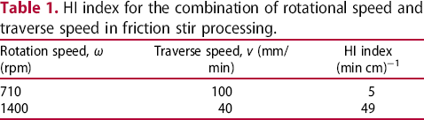
HI index for the combination of rotational speed and traverse speed in friction stir processing.
HI index for the combination of rotational speed and traverse speed in friction stir processing.
In composite fabrication, increasing the number of FSP passes leads to a uniform distribution of reinforcement particles in the matrix and finer grains. Two to four passes are required for uniform distribution of particles but higher passes resulted in excessive loss of matrix material. However, at LH input parameter combination can result in defects such as voids even after multiple passes. Typical microstructures of the base aluminium alloy, aluminium alloy friction stir processed at LH condition and HH condition, and surface composites fabricated at LH and HH condition are shown in Figure 3(a–f). Stirred zone by the tool probe is referred to as a surface composite. In the stirred zone, reinforcement particles are distributed in the matrix by the action of the rotating tool probe.
The optical microstructure of (a) base AA5083 alloy, (b) defect in stir zone of friction stir processed alloy in LH conditions, (c) FSP alloy in HH conditions, (d) defect in stir zone of surface composite fabricated in LH conditions, (e) distribution of reinforced particles in stir zone of surface composites fabricated in LH conditions and (f) surface composites fabricated in HH conditions.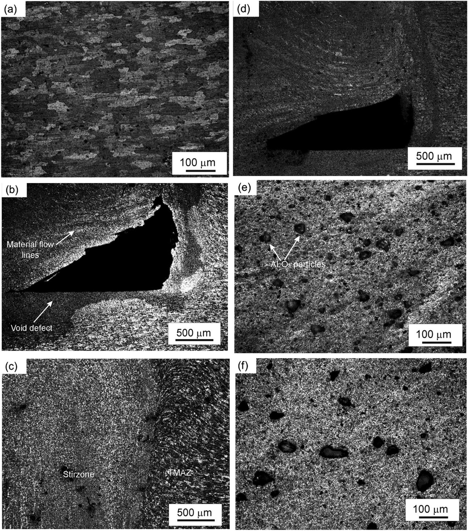
The microstructure of base alloy shows elongated grains with an average grain size of 80 μm (Figure 3(a)). The other phases are also discernable as black dots in a matrix of the base alloy. In AA5083 alloy, such black phase is often reported as Al6(Mn, Fe) [18,19]. A large void in the stir zone is observed in LH condition of FSPed alloy as shown in Figure 3(b), whereas defect free stir zone is observed in HH condition, as shown in Figure 3(c).
The formation of a void in the stir zone is due to decreased material flow during stirring in LH condition. The void is also observed in surface composites prepared in LH condition (see Figure 3(d)). The circular and tangential lines of material flow intersect above the defect, which indicates insufficient material flow in this region. Sharifitabar et al. [19] also observed large voids and tunnels in the stir zone of AA5052/nano alumina surface composite, FSP at a low ratio of rotation speed to tool traverse speed. In the present study, the size of reinforced particles is also reduced to 25–50 μm due to intense stirring action imposed during FSP (Figure 3(e,f)). In surface composites prepared in LH condition, the particle size reduction is more pronounced as compared to that prepared in HH condition. This is attributed to the longer stirring time available during processing at lower traverse speed. Figure 3(e) shows the uniform distribution of reinforcement particles in the stir zone of composite processed in LH condition. Similarly, the reinforcement distribution is uniform in the stir zone of composite processed in HH condition, as observed in Figure 3(f). Clustering of alumina particles is not observed for the surface composite prepared in any condition of HI.
The hardness profiles of the cross-sections of the FSP AA5083 alloy and AA5083-Al2O3 surface composites in different conditions are shown in Figure 4. The grain refinement by FSP results in an increase in maximum hardness up to 95.7 HV as compared to base alloy average hardness of 80 HV. Results from the present study indicate that the alloy FSPed in LH condition exhibits a higher average hardness of 90 HV as compared to the alloy processed in HH condition (86 HV). In FSP, low rotational speed generates less amount of heat and high traverse speed decreases the time of contact of the tool with the material. The heat-induced grain growth may contribute to lowering the hardness of the alloy processed in HH condition. Hardness variation due to HI was also reported by various researchers [11,20]. In composites, the hardness shows different behaviour. The composite processed in HH condition exhibits a maximum hardness of 126 HV (average hardness 114 HV) in stir zone compared to the maximum hardness of 109.2 HV (average hardness 100 HV) in stir zone of the composite processed in LH condition. This is attributed to the decrease in material flow due to the presence of non-deformable alumina reinforcement. HH input is required for sufficient material flow in the stir zone, while low traverse speed favours the improved mixing of reinforcement particles in the matrix. Barmouz et al. [21] also showed that low traverse speed provides a uniform dispersion of particles and improved properties in Cu/SiC surface composites. Azizieh et al. [22] also pointed out that the increase in rotation speed enhances the material flow in fabrication of AZ31/alumina composites.
Hardness profiles of the FSPed alloys and surface composites.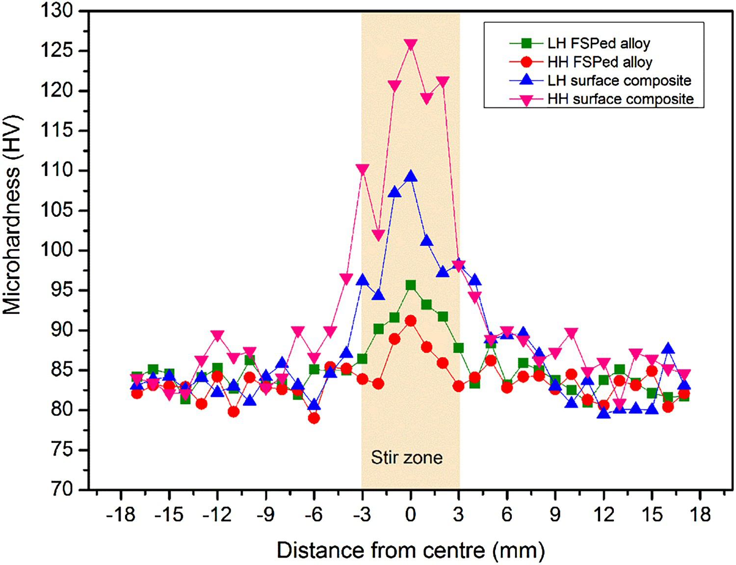
In general, the friction increased during the initial running-in period and achieved steady state in ∼100 s for the investigated tribocouples. The average coefficient of friction (COF) in steady state for the investigated materials is shown in Figure 5. The COF varied in a narrow range from 0.22 to 0.27 for all materials sliding against steel at a given load (except for base alloy at 5 N load). Higher COF in base alloy can be attributed to dislocation interaction by Mg solute atoms. In Al–Mg alloys, Mg solute atoms interact with the mobile dislocations during plastic deformation. This phenomenon is observed as serrated yielding in stress–strain curve of the Al–Mg alloys and known as Portevin-Le Chatelier effect [23]. In this study, COF of the base alloy is higher at a lower load due to interaction of dislocations by Mg solute atoms. However, at higher loads dislocations can easily overcome the solute interaction effect. Zahmatkesh and Enayati [24] reported an average steady-state COF of 0.31 for FSPed surface composite reinforced with alumina particles of 50 nm size in AA2024 alloy. Mostafapour and Khandani [25] observed an average COF of 0.35–0.40 when nanosized alumina particles reinforced AA5083-H116 surface composite was sliding against steel. It is known that sliding of aluminium alloy in ambient conditions leads to the oxidation of the contacting surface, resulting in the formation of alumina at the contact. Previous investigators reported that the sliding of alumina in moderate or high humid environments leads to the formation of aluminium hydroxide rich layer at the contact [26,27]. As laboratory conditions in the present study fall in moderate humidity range (60 ± 5% RH), the formation of aluminium hydroxide rich layer is possible at the contact and can be attributed for the negligible effect of sliding load or surface conditions on the frictional behaviour. In HH condition composite, the COF is lower at higher load of 20 as compared to lower load of 5 or 10 N. This can be ascribed to the enhanced tendency for the aluminium hydroxide formation due to increased deformation and oxidation at higher load. However, in LH condition composite the COF varies in a narrow range suggesting the formation of unstable aluminium hydroxide layer formation.
The average steady-state COF for investigated alloys and composites.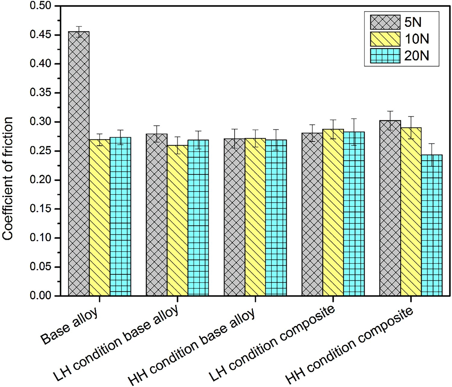
The surface profiles after wear test of the investigated samples indicate that the wear increases with the increase in load. The waviness and depth increase with increase in load.
Worn surface profiles of base alloy FSPed in HH condition and surface composite FSPed in HH condition is shown as a function of load in Figure 6(a,b). The depth or width of the wear scar is almost the same at a lower load of 5 N, for both alloy and surface composite, but increased with increase in load. The fluctuations in the surface profiles also increased with an increase in sliding load, indicating rough surface due to increased material removal. On comparing worn surface profiles of FSPed base alloy with FSPed composite, it is evident that the depth or width is almost same at a lower load of 5 N. The presence of a large number of fluctuations in case of FSPed composite is due to the protrusion of ceramic particles on the worn surface. However, the depth significantly reduced for FSPed composites when compared against that for FSPed base alloy.
Worn surface profiles after wear test (a) base alloy FSPed in HH conditions after wear at 5, 10 and 20 N (b) composite FSPed in HH conditions after wear at 5, 10 and 20 N.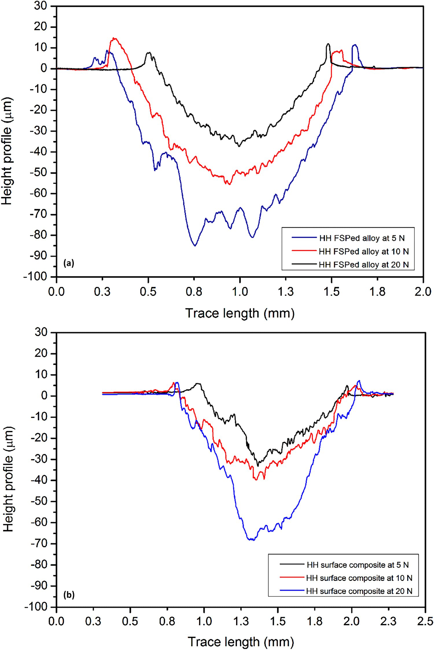
Figure 7 shows the wear rate data for all investigated materials at different loads lie in the range of 2 × 10⁻³ to 7.5 × 10⁻³ mm3/m. The lowest wear rate is observed for the surface composites FSPed in HH condition sliding at all investigated loads, whereas the highest wear rate observed for the base alloy sliding at 20 N load. Superior wear resistance of HH condition surface composite can be attributed to the high hardness and formation of the hydroxide layer. In humid condition, the hydroxide layer reduces the tendency of formation of adhesive junctions between tribopairs. Iacob et al. [28] reported the formation of tribolayer for aluminium-alumina-graphite hybrid composite prepared by powder metallurgy route. Results from the present study indicate that the wear rate decreased with an increase in load for any material. At a given load, the surface composite prepared in HH condition shows less wear, whereas base alloy shows high wear. In case of base alloy, the wear resistance of base alloy is better when FSPed in HH condition as compared to LH condition. For a given HI condition, the surface composite exhibits superior wear resistance than the base alloy.
Specific wear rate of the investigated base alloy, FSPed alloy and FSPed composites.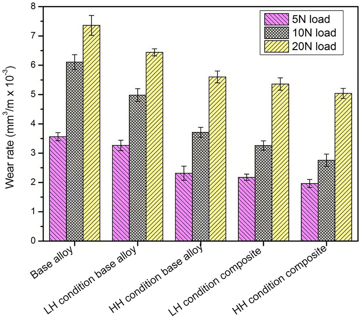
The effects of HI conditions in FSP and load conditions in sliding on wear mechanisms of the investigated aluminium alloys and composites were studied using SEM analysis. The worn surface of the base alloy at 5 N load reveals the flow of material in the direction of sliding, as shown in Figure 8(a). The asperities flatten at the contact and the material flows in the form of layers by ploughing action of the hard steel counterbody. The material is also extruded on sideways of the track. In base alloy FSPed in LH condition, the worn surface shows micro cracks on the deformed or extruded surface as shown in Figure 8(b). In the case of composite FSPed in LH or HH condition, the surface after sliding at a lower load of 5 N shows protrusion of reinforced ceramic particles. Typical worn surface of composite FSPed in LH condition indicates that the reinforcement particles bright in contrast in Figure 8(c) are strongly bonded to the aluminium alloy matrix. The protruded ceramic particles on the surface are attributed to fluctuations observed in surface profiles of worn composites as shown in Figure 5(b).
SEM images of the surfaces after wear at 5 N load (a) base aluminium alloy, (b) aluminium alloy FSPed in LH conditions and (c) aluminium alloy–alumina composite FSPed in LH conditions.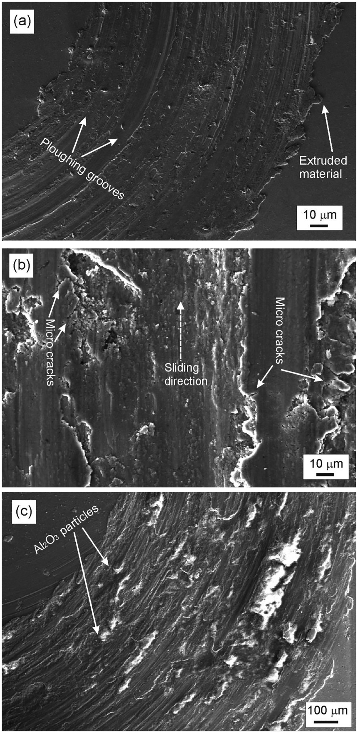
At an increased load of 10 N, the flow of material is generally increased and worn surfaces show areas of removed material. Furthermore, the deformed material forms layers in sliding direction and also extrudes in a perpendicular direction to the sliding. The adhesive wear is observed on the worn surface of FSPed alloy, as shown in Figure 9(a). In surface composites, the reinforcement particles effectively protect the matrix material, as noted in Figure 9(b,c). In addition to ploughing, delamination also appears to contribute to material removal for the composites prepared in HH condition as shown in Figure 9(c).
SEM images of the surfaces after wear at 10 N load (a) aluminium alloy FSPed in HH conditions, (b) aluminium alloy–alumina composite FSPed in LH conditions and (c) aluminium alloy–alumina composite FSPed in HH conditions.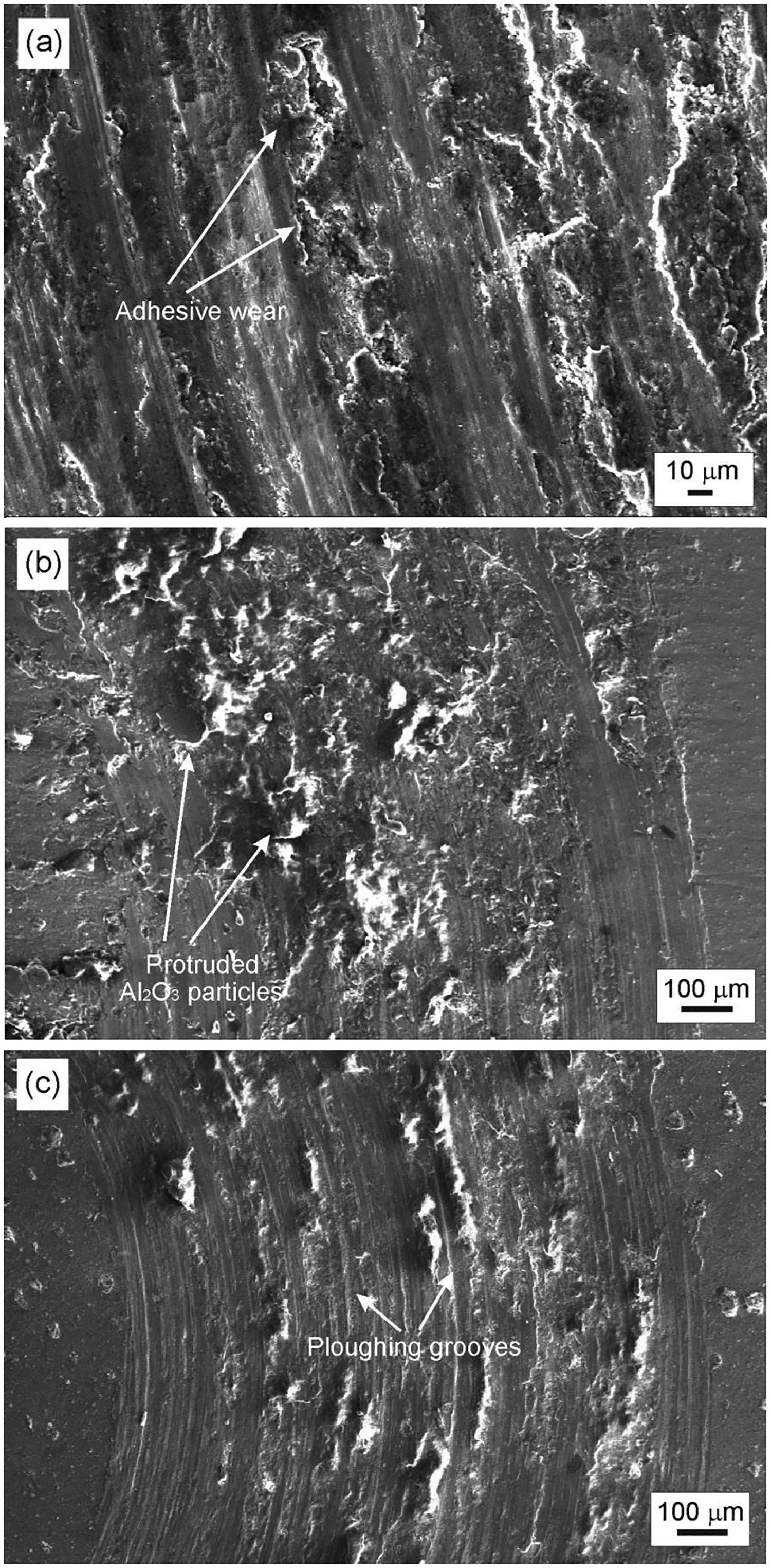
At a higher load of 20 N, the delamination wear is the dominant mechanism in aluminium alloy FSPed in LH condition, as shown in Figure 10(a). The subsurface cracks propagate and link at the surface leading to the delamination [29]. The microcracks are observed on sideways of deformed surface almost in a perpendicular direction to the sliding for the composite prepared in LH condition as shown in Figure 10(b). Cracks observed on the surface are originated from subsurface deformation of matrix due to repeated rubbing in sliding. The delaminated regions with deeper ploughing grooves are observed on the worn surface of the composite prepared in HH condition as shown in Figure 10(c). The material removal by delamination is more pronounced at higher load as an increase in load accelerates the crack propagation.
SEM images of the surfaces after wear at 20 N load (a) aluminium alloy FSPed in LH conditions, (b) aluminium alloy–alumina composite FSPed in LH conditions and (c) aluminium alloy–alumina composite FSPed in HH conditions.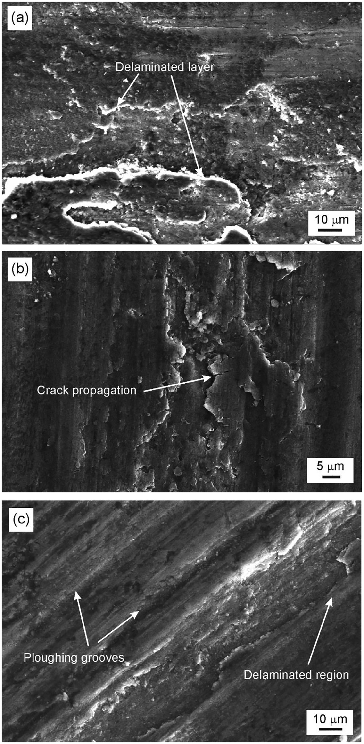
SEM images of worn counterbody ball surfaces show signatures of adhesion. Thick adhered material is generally found as layered chunks on the periphery of the circular impression on the worn ball surface. Typical SEM images of steel balls worn at 20 N load against aluminium alloy FSPed in HH condition composite are shown, respectively, in Figure 11(a,b). The EDS analysis is shown in Figure 11(b) suggests that the layers on the worn steel balls are rich with oxides of Al and/or Mg. Further, the large concentration of Al and Mg essentially indicates significant transfer material from the disk to ball surface.
SEM images of the ball worn at 20 N against (a) aluminium alloy FSPed in HH conditions and (b) aluminium alloy–alumina composite FSPed in HH conditions. EDS analysis for (b) is also shown.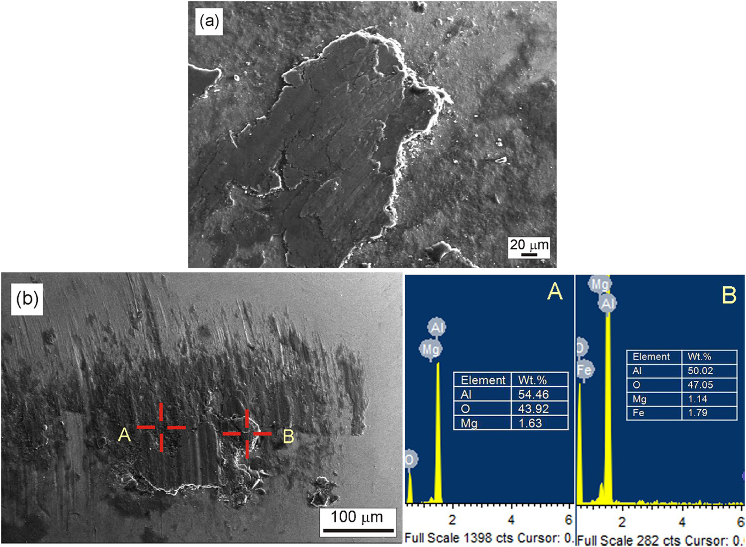
The preferred direction of material transfer from disk to ball observed in the present study can be ascribed to the large difference of hardness between steel ball (∼750 HV) and aluminium alloy or composites (80–130 HV). A similar effect of the difference in hardness of contacting materials on the direction of material transfer during sliding was reported previously [30–32]. Edalati et al. [31] also found adhered material on the ball surface in ball-on-disk wear testing of high-pressure torsion processed Al-alumina composite. Jerina and Kalin [32] observed material transfer after just 2 mm of sliding in cross-cylinder configuration wear testing of an extruded round bar of aluminium 6060 alloy against AISI H13 tool steel. As per the adhesion considerations proposed by Chen and Rigney [33], the preferred transfer direction is from the cohesively weaker material to the cohesively stronger material. On the other hand, the transferred fragments are known for their mechanical mixing, i.e. crushing, mixing and compaction to form a mechanically mixed material (MML) on the sliding surfaces [34,35]. SEM and EDS analysis of worn disk surfaces in the present study does not indicate the formation of such MML. But the significant presence of oxygen is observed. It is to note that the formation and stability of MML is governed by environment and materials in the tribosystem [34,35]. In the present study, as iron is not observed on worn disk surfaces, the formation of stable MML is said to be not favourable.
Detailed analysis of wear debris is necessary to understand the conditions to which the tribosystems were subjected and mechanisms of debris generation. Debris particles are known to be generated from the rupture of MML [33,34] or transferred material within the tribosytem [34]. Sliding at high loads leads to mechanical alloying and deformation of wear debris that further result in the formation of oxides or intermetallic compounds [36].
The EDS analysis of wear debris is shown in Figure 12(a,b). In this study, elements from counterbody steel ball such as iron, chromium are neither found in flaky debris obtained from worn base alloy nor in fine irregular wear debris obtained from the worn composite. This suggests that debris particles are originated from the matrix material. However, the presence of a large concentration of oxygen observed in EDS analysis suggests oxidation and/or hydroxidation of the ruptured oxide layer or crushed reinforcement particles. In sliding wear of alumina, Gee [26] reported that hydroxide phases tend to form in humid environmental conditions.
SEM-EDS analysis of debris collected after wear at 20 N load (a) aluminium alloy–alumina composite FSPed in LH conditions (b) aluminium alloy–alumina composite FSPed in HH conditions.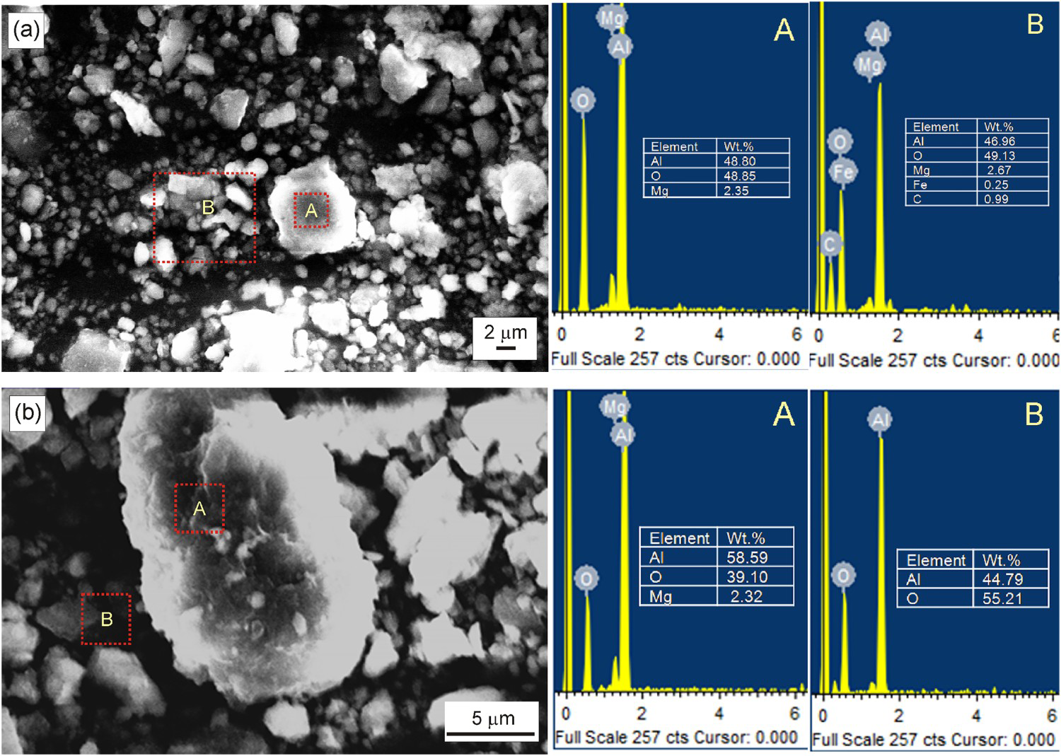
To confirm the presence of hydrated phases in wear debris, thermogravimetry (TG) analysis of debris generated during sliding at 20 N load is performed, and results are shown in Figure 13.
TG analysis of debris collected from worn base alloy and surface composite FSPed in HH conditions after sliding at 20 N load.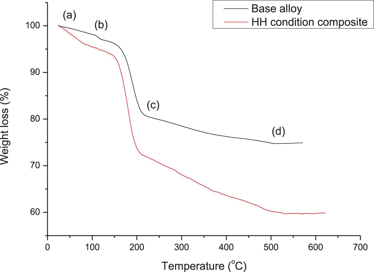
In the present TG study, the initial weight loss of 2–5% observed up to 100°C in TG curve (from (a) to (b) in Figure 13) corresponds to the evaporation of physically adsorbed moisture from debris particles. The weight loss up to 200°C is nearly 26% and 20% for surface composite and base material debris, respectively. The weight loss from 200°C to 500°C (from (c) to (d) in Figure 13) in debris collected from surface composite is large as compared to that collected from base alloy. The weight loss recorded at 500°C is nearly 40% and 25% for surface composite debris and base material debris, respectively. This weight loss corresponds to the dehydroxilation of hydrated phases in the wear debris. Thus, TG analysis of wear debris confirms the formation of hydroxide based phases during sliding. Further, the TG analysis also reveals that debris from surface composite is highly hydrated as compared to debris from base alloy. The increased hydration in the surface composite can be attributed to the presence of alumina, the formation of which is already explained in the earlier section.
Kim et al. [36] in sliding wear of steel against aluminium at 95% humidity conditions also attributed weight loss from wear debris due to the effect of hydroxylation on the contact surface. XRD analysis of wear debris generated at 20 N load from the surface composite FSPed in HH condition and alloy FSPed HH condition, unworn surface composite FSPed in HH condition and base alloy is shown in Figure 14. XRD patterns for wear debris in the study are similar to that reported for ball-milled Al-5% Mg nano crystalline alloy [37]. XRD analysis indicates the presence of aluminium, while hydroxidated and other phases are not found. Also, the broadened peaks of wear debris suggest size reduction of grains due to crushing between steel ball and disc [36,38]. Furthermore, the peak broadening for wear debris generated from surface composite is large as compared to wear debris collected from FSPed alloy. This can be attributed to the crushing of less material as well as minimum presence of flake type debris in case of a surface composite. Combining this with the result from TG analysis, it can be stated that the wear debris was hydroxidated and their size was reduced to large extent during sliding.
XRD analysis of wear debris of surface composite FSPed in HH conditions after wear at 20 N load, aluminium alloy FSPed in HH conditions after wear at 20 N load, unworn composite and unworn base aluminium alloy.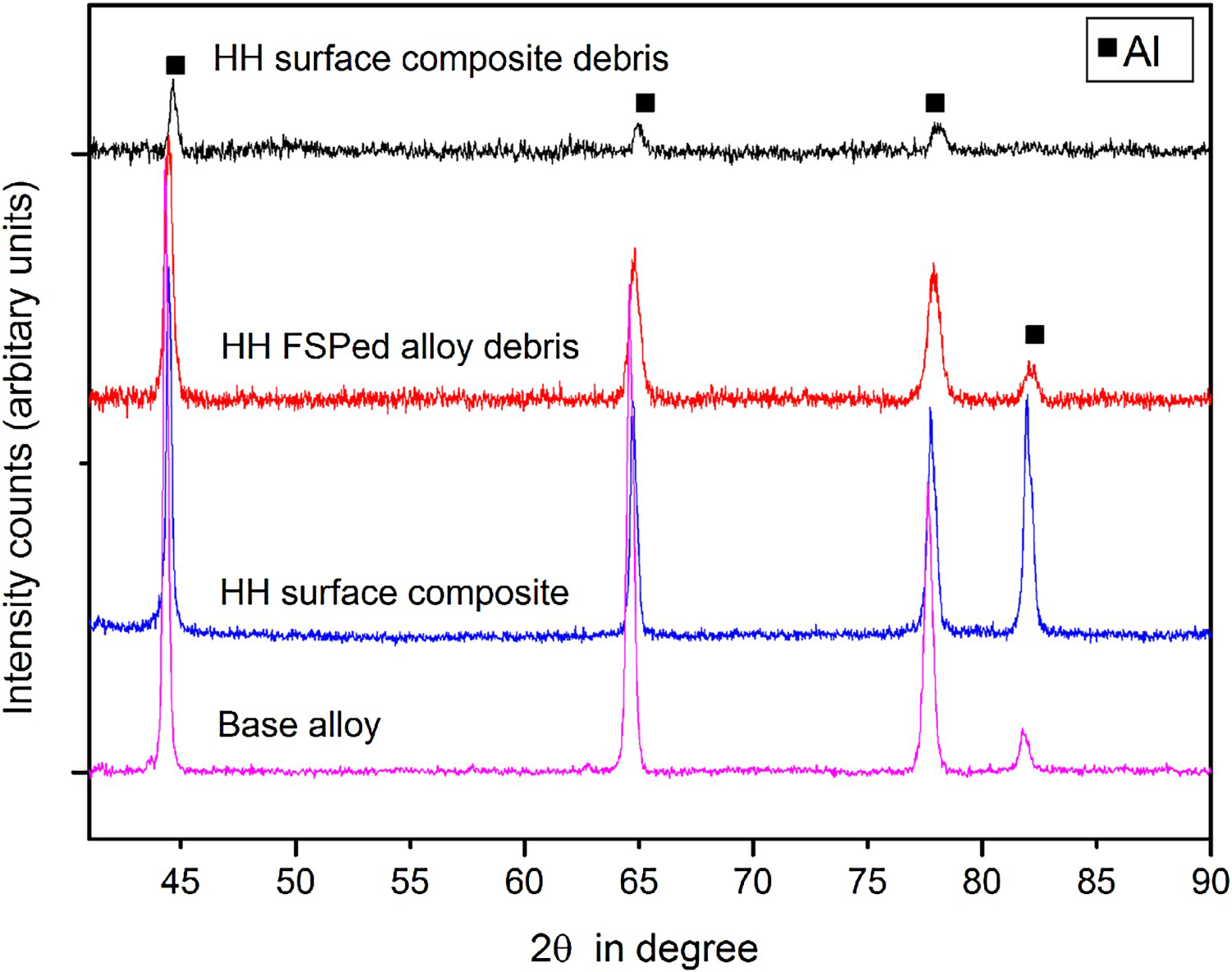
TEM analysis of debris generated from HH condition surface composite worn at 20 load is done to estimate the size and crystallinity of debris particles. Figure 15(a,b) show that the size of debris particles varies in a large range from ∼10 to ∼200 nm. Moreover, the strong bonding of ultrafine size debris is clearly visible in Figure 15(b). The selected area diffraction pattern (SAED) suggests that the particles are partly crystalline as shown in Figure 15(b). The continuous sliding over trapped particles results in their size reduction. The sliding process is considered to be analogous with ball milling process where wear particles under the compressive and shear forces are deformed, fractured and welded repeatedly to generate ultrafine size debris [34,35]. Rigney et al. [34] demonstrated that with a similar material and environmental conditions, the resultant material after ball milling and sliding wear is identical. In the early stage of sliding, debris particles are ejected out from the wear track and as sliding progresses, the wear track cavity acts as a reservoir for particles. The trapped particles in the wear track are subjected to repeated deformation leading to size reduction. Summarizing the debris analysis using XRD, TG and TEM, debris particles are generated from the softer disk body and reduced in their size. The ultrafine size debris particles are hydroxidated in sliding of surface composites against steel in the selected wear conditions.
TEM analysis of debris of surface composite FSPed in HH conditions after wear at 20 N load (a) ultrafine size wear debris, (b) welded ultrafine wear debris and corresponding SAED pattern.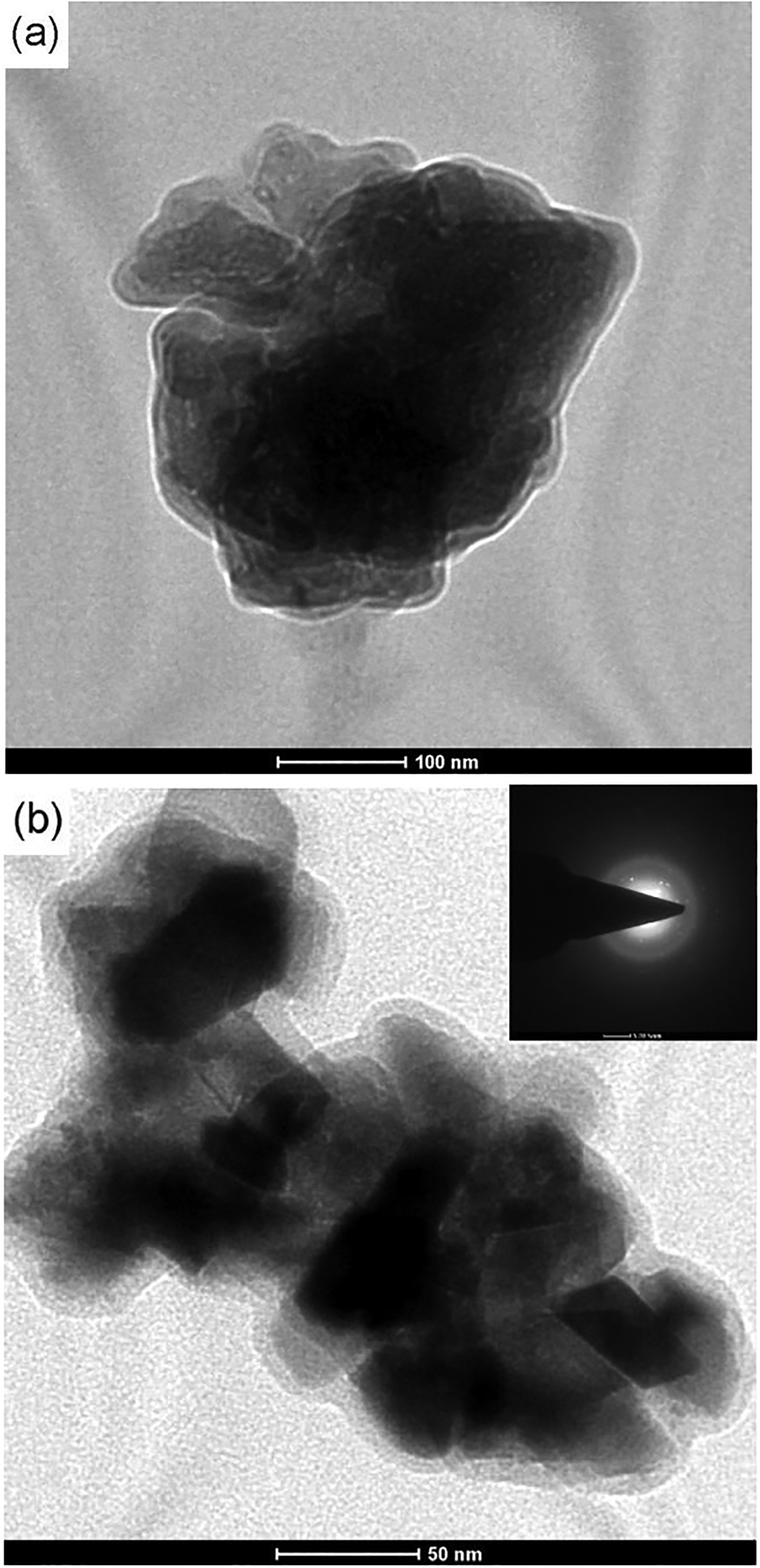
AA5083 aluminium alloy–alumina surface composites are prepared by friction stir processing at LH input condition obtained from 710 rpm to 100 mm/min combination and HH input condition obtained from 1400 rpm—to 40 mm/min combination. Microstructure and mechanical characterization of the base material, FSPed alloy, FSPed surface composites are studied. Ball-on-disk wear testing against commercially available steel ball is done to understand the tribological behaviour at 5, 10 and 20 N load in ambient conditions of 25 ± 5°C and 60 ± 5% RH. The following are the major conclusions:
The surface composite fabricated in LH input condition exhibits defected stir zone, whereas HH input condition renders defect free stir zone. The surface composite fabricated in HH input conditions shows the highest hardness of 126 HV in tested combinations. The sliding wear against steel ball indicates increased wear resistance with an increase in HI condition of FSP for composites or alloy. There is no significant change in the frictional behaviour. The worn surface investigation shows that ploughing and adhesion are dominant wear mechanisms at low load of 5 N, whereas adhesion and delamination are pronounced at a high load of 20 N. The high input conditions in FSP renders increased material flow during sliding. At the high load, of 20 N a small amount of material transfer occurred from steel ball whereas at other loads material is transferred from disc to the steel ball. Wear debris analysis using EDS, TG, XRD and TEM techniques indicate that debris particles are reduced in their size and bonded during the sliding process. The hydroxidation of the wear debris influences the friction and wear of FSPed surface composites.
Footnotes
Disclosure Statement
No potential conflict of interest was reported by the authors.