
Abstract
A novel tribological rig-based approach is presented for the selection of engine oils with reduced friction characteristics. A combined experimental and numerical investigation has been performed to compare and assess the friction between the piston ring and liner of two different passenger cars lubricated with two different commercial engine oils. The experimental investigations were performed on reciprocating tribo-tester using actual piston ring and liner as the test specimens. The experiments were performed to investigate the influence of contact load and reciprocating frequency on the contact friction. The numerical investigation has been performed with the help of a mathematical model developed using the modified Reynolds equation considering the flow factors for Gaussian surfaces along with Greenwood and Trip's asperity contact approach. The numerical results have been used to justify and correlate the experimental findings. This paper presents an approach for selection of engine oil for two popular passenger cars in the Indian market.
Keywords
Nomenclature
Ring face geometric parameter
effective width of piston ring
oil film pressure
asperity contact pressure
gas pressures at the inlet and outlet of lubrication region
physical width of the ring
Composite Young's Modulus

function relating to the probability distribution of asperity height
h/σ = H/ σ*

number of asperities per unit contact area
nominal radius of piston ring
Ring face geometric parameter
asperity radius of curvature
angular frequency of crankshaft
variance of the composite surface roughness


contact factor defined by Wu and Zeng [1]
Poisson's Ratio
Non-dimensional parameters


Introduction
Rapid industrialization and globalization have increased the purchasing power of individuals and so the number of automobiles has increased over the past couple of decades. The automobile consists of a single-power generating unit namely the internal combustion (IC) engine that untiringly produces power not only to propel the automobile but also to overcome the frictional losses. Hence, focus on the development of vehicles with enhanced efficiency and reduced environmental impact has gained momentum [2]. The stringent environment norms and the ever-increasing demand from the consumers have resulted in the development of compact engines with enhanced efficiency [3]. This, however, has challenged tribologists and the design engineers to investigate and optimize the parameters responsible for improved efficiency. Holmberg et al. [4] through detailed calculation presented that in a passenger car only 21.5% of fuel energy is used to move the car while the rest is lost in overcoming friction. The piston ring liner system forms the most critical part of the IC engine and for reducing fuel consumption; reduction in cylinder-piston friction is highly desired [5]. The Tribology of this system is governed by parameters related to piston and ring dynamics [6], metallurgy of the ring and liner [7], surface roughness [8] and lubricant dynamics.
The use of an appropriate lubricant has been an important aspect for reducing friction between the ring liner contacts. Rigorous research in this regard has resulted in the formulation of standards and procedures for the testing and evaluation of lubricants for automotive applications [9]. Appropriate engine oil not only protects the surfaces from metal to metal contact but also enhances the drain intervals. Lubricant age has proved to be detrimental in contact friction between the ring and the liner [10]. High temperatures prevailing in the engines result in oxidation and thermal degradation of engine oils. This, in turn, results in the formation of sticky deposits on the piston ring and the liner which further increases the friction between the contacting surfaces [11]. The tribological performance of the engine oils can be correlated with their physico-chemical and rheological characteristics. Hence, the selection of appropriate engine oil is vital for the improved friction resistance between the ring liner contacts [12].
The friction encountered in an engine has often been tested and evaluated using various engine test bench studies. However, engine test bench studies are not only time-consuming but also a very costly approach. Hence, Truhan et al. [13] proposed a rig test to measure friction between the piston ring and liner. The tests were performed using ring segments on a flat specimen. Similarly, Woydt and Kelling [14] advocated the tribological testing of lubricants and materials outside engines. The proposed testing protocol could be used for comparative assessment of tribological behaviour of lubricants. Similar testing protocols have been proposed by various researchers that are able to provide useful and reliable information on the lubricant selection for engines in reduced time and budget, eliminating the need for costly and time-consuming engine test bench studies [15].
The approach of mathematical modelling also gained wide popularity in predicting the tribological performance of piston ring liner contact. The earliest models developed in this regard age back to 1930s when Castelman made the calculations on piston and liner. Extensive work has been done since then to understand the exact lubrication behaviour between piston ring and liner mainly at the Top Dead Centre (TDC) and the Bottom Dead Centre (BDC), where the boundary and mixed lubrication is a predominant phenomenon and is a major source of power loss in the form of friction. The piston during its travel from TDC to BDC encounters Mixed/Boundary lubrication at the dead centres and Hydrodynamic lubrication at the mid-stroke. The top compression ring is more vulnerable to the high combustion gas temperature and pressure and contributes to approximately 16% to the total piston friction. As a result of this, the contact formed between the top compression ring and the liner has gained significant interest for tribological research. In recent years, more refined models considering the effect of rough surfaces, asymmetric loading and thermo-elastic behaviour of piston rings have been developed. Reynolds equation forms the basis of all the analytical models developed so far. The modified average Reynolds equation was proposed by Patir and Cheng [16,17] by introducing flow factors. The concept of flow factors has since then been well acclaimed to investigate the lubrication phenomenon in rough contacts. Many studies have been carried out to extend the work done by Patir and Cheng by formulating the flow factors. One of the pioneering works in this context is of Cho et al. [18] on the determination of flow factors for elastically deformable Non-Gaussian rough surfaces. Morales-Espejel [19], with the help of stochastic averaging technique as devised by Christensen and Tonder, derived the pressure-flow factors.
Most of the studies aimed at studying piston ring cylinder liner lubrication behaviour assume Gaussian distribution for the asperities. Sun [20] solved the non-uniform contact problem between the piston ring and liner considering the arbitrary features specified by the shape of liner and free ring. A major breakthrough in the analysis of piston ring liner tribo-system was presented by Hu et al. [21], considering the non-axisymmetric loading in the circumferential direction of the piston ring. Ozgen et al. [22,23] studied the friction between the piston ring and liner system under a mixed lubrication regime. The authors while taking into account the asperity contact load derived a correlation between liner wear and the load supported by surface asperities.
In the present study, a novel tribological approach has been presented for the selection of engine oils with reduced friction characteristics. A combined approach of experimental and numerical modelling has been followed to investigate the contact friction between the piston ring liner contacts of two different vehicles lubricated with two different commercial engine oils. Among the two oils selected, one is the original equipment manufacturer (OEM) recommended for both the vehicles, while the other is a competitor candidate of the same SAE grade. The experimental approach is able to clearly differentiate the friction behaviour of the contact. However, the mathematical simulation results suggest the reasons for the difference in the performance behaviour of the lubricated ring liner contact. The model is solved to obtain the lubricant film thickness and the load shared by the lubricant film and the contacting asperities. This combined experimental and numerical approach has proved to be useful for selection of engine oils for reduced friction in piston ring liner contacts.
Background
Specifications of selected vehicles.
Specifications of selected vehicles.
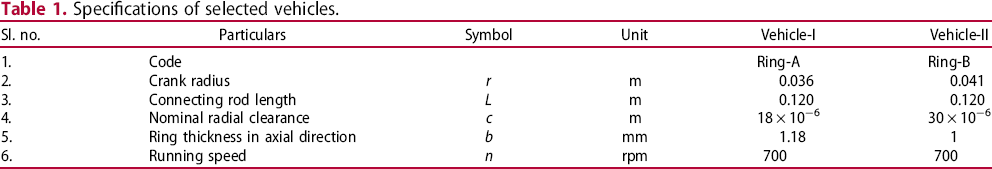
Lubricant properties.
The experiments have been performed using Ring-A and Ring-B contacts in a reciprocating tribo-tester. The contacts were lubricated with both Lube-1 and Lube-2 and comparative assessment of the friction behaviour undertaken. The influence of operating parameters, namely, the applied load and reciprocating frequency on the friction behaviour has been assessed. The numerical simulations have been performed using the entries given in Tables 1 and 2 as model inputs. The lubricant film thickness within the contact and the load shared by the contacting asperities and the lubricating film has been determined. The results obtained from the experimental investigation have been justified using the numerical findings.
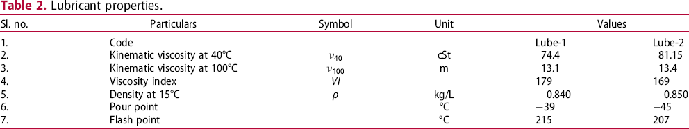
The test specimens for the contacts Ring-A and Ring-B are shown in Figure 1. The rings were used as such while the liners were cut into sections using wire-cut electrical discharge machining (EDM). The rings used in Ring-A and Ring-B had the hardness of 65.22 and 67 HRC, respectively.
Actual ring and liner test specimens.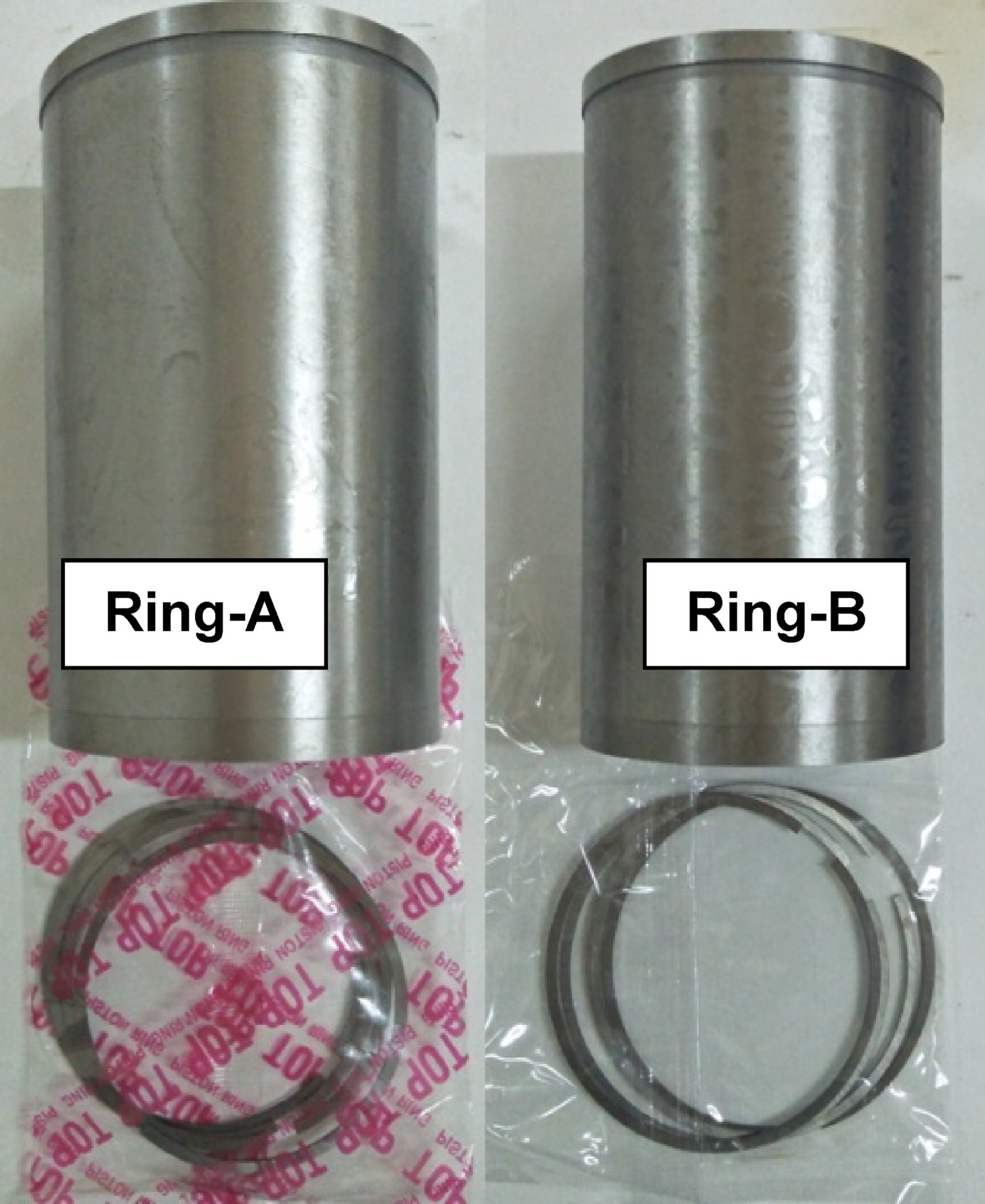
The experiments were performed on a reciprocating tribo-tester (Rtec, USA) shown in Figure 2. The cut section of the liner was housed on the reciprocating stage and allowed to reciprocate at the desired frequency. The piston ring was attached to the friction arm with the help of a specially designed fixture and held stationary. The contact was loaded with the help of servo motor and lubricated using the selected engine oils.
Experimental test setup.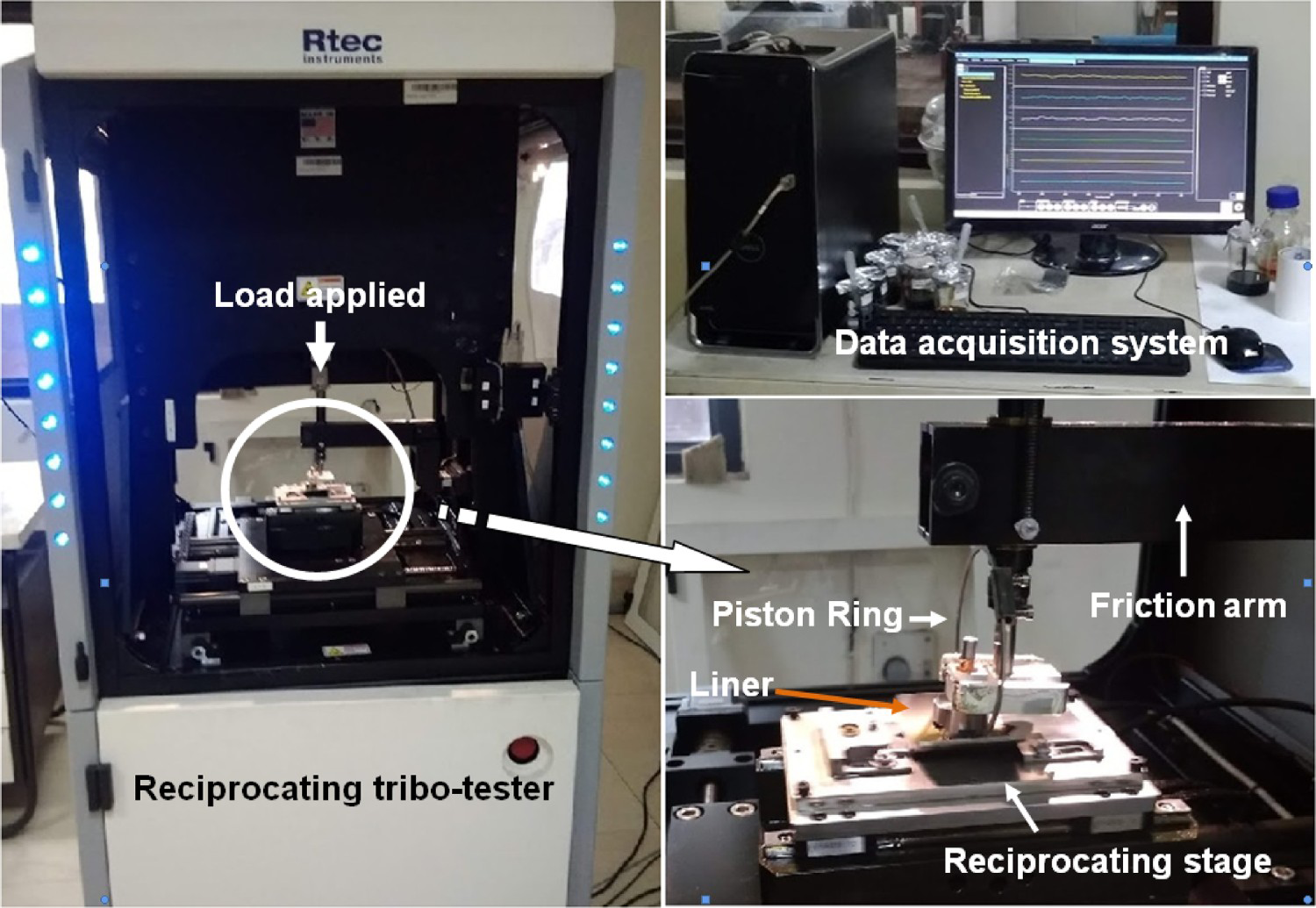
The experiments were conducted at room temperature in line with the test procedure of ASTM G:133. The contact was loaded with 25, 50 and 100 N load. In order to have a sufficient stroke length, the reciprocating frequency was limited to 1, 3 and 5 Hz. The contact friction was continuously monitored and recorded. Each of the experiment was repeated to ascertain the reproducibility of the test results.
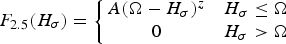
The numerical model for piston ring liner contact has been developed considering the co-ordinate system shown in Figure 3(a). The piston reciprocates along y-axis, whereas z-axis directs in radial direction and also represents the lubricant film thickness.
Piston ring liner contact geometry; (a) coordinate system and (b) ring profile.
The piston ring cross-section is assumed to follow Furuhama's approximation in which the ring profile consists of central flat region bounded by two quadratic curves. Neglecting the tilting of ring, the ring face is expressed as follows:
It is assumed that lubricant is available in the region between ‘− b/2’ to ‘b/2’. The lubricant film thickness h(y, t) is expressed by the following equation:

Basic Assumptions: The modified average Reynolds equation forms the governing equation used to determine the hydrodynamic pressure within the lubricant film. The equation is derived assuming the following:
The piston ring is divided circumferentially into ‘n’ number of equal segments and ‘pmax’ is assumed to be the maximum pressure acting on individual segment. The length of individual segment is much larger than the width (b) of the ring. The liner is stationary and piston ring is reciprocating with the velocity ‘U’. Hence, U1 = U; and U2 = 0 for the contact. The squeeze effect is neglected and no cavitation is assumed to occur during piston stroke.
The Reynolds equation and the boundary conditions in the non-dimensional form read:

Here the flow factor
 accounts for the change in flow resistance with roughness. Flow factor
 accounts for the fact that if roughnesses of the two surfaces are unequal, there will be a net transport of fluid through the troughs on the surfaces. The flow factors developed by Morales-Espejel for the lubricant flow in transverse roughness has been used where, SK = 0, and K = 3 for Gaussian surfaces. Integration of Equation (3) yields:
Equation (5) is solved using numerical integration technique to obtain the lubricant pressure on a segment.
Asperity Contact pressure: The average pressure due to contact of asperities has been calculated using Greenwood and Tripp's model as follows [24]:
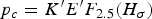
Assuming that the surfaces follow Gaussian distribution, F2.5 (Hσ) as given by Hu et al. [21] is,
 = 4.0, A = 4.4068 × 10⁵, Z = 6.804, and K = 1.198X10⁴. In the present case,
 = 0.04 and
 = 0.001, are considered as given in literature.
Load Equations: As described by Hu et al. [21], the reaction force acting on piston ring segment is shown in Figure 4.
Forces acting on the ring surface.
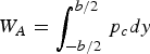
The force due to hydrodynamics on the ring face, i.e. in the region (−b/2, +b/2).
The force due to Asperity contacts in the region (−b/2, +b/2).
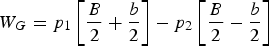
The force due to combustion gases in the region (−B/2, −b/2) and (+b/2, +B/2).
For equilibrium in a radial direction

Numerical Solution: The model described is solved using MATLAB code. The contact characteristics of Ring-A and Ring-B along with the lubricant characteristics are given in Tables 1 and 2 are used as input to the model. Reynolds equation is solved for the pressure using an initial film thickness along with the inlet and outlet pressures, as shown in Figure 5.
Inlet and outlet pressures at the piston ring face.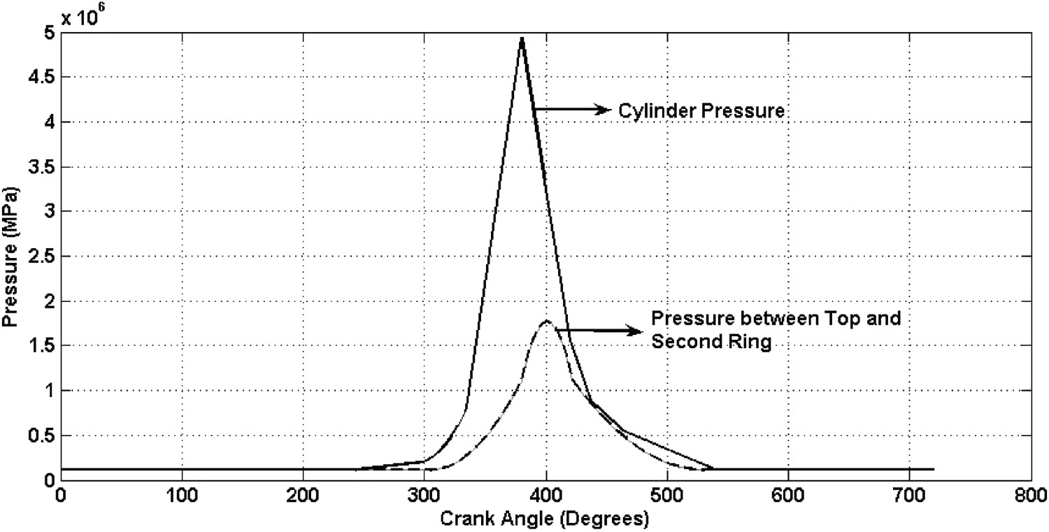
With the help of the assumed initial value of minimum oil film thickness hc, ring face profile is determined using Equation (1). The ring face is divided in axial direction into 200 equal segments. For each segment, pressure-flow factor
 , shear flow factor
 and contact factor
 are calculated using film thickness value given by Equation (2) for a particular segment and crank angle. Subsequently, the pressure exerted by the lubricant film on a particular ring segment is calculated. The total oil film load exerted by lubricant on the ring face and Asperity contact load is computed using the load equations, at the particular crank angle. The gas force acting in the direction opposite to that of the oil film load and asperity contact load is computed using Equation (10). The load balance Equation (11) if not satisfied for the assumed value of minimum film thickness hc, the initial value for hc is increased by hc = hc + Δhc. The whole system is used in an iterative loop until the load balance is satisfied. The new film thickness is obtained according to a predetermined accuracy for that particular crank angle value. The procedure is repeated again for other crank angles.
Experimental Results: In order to have a better judgment, the experimental findings are presented in the form of influence of operating parameters on the contact friction. Figure 6(a,b) shows the influence of load on the contact friction, it is observed that the friction decreases with increase in load irrespective of the lubricant and the ring selected. Such a behaviour in contact friction can be attributed to the presence of extreme pressure (EP) additives blended in engine oils. The EP additives get activated at higher contact stress and form strong protective lubricant films thereby reducing the metal to metal contact and the associated contact friction. Further, it is observed from Figure 6(a) that at lower reciprocating frequencies, the friction curve over the time is stable. However, with an increase of frequency, as shown in Figure 6(b), the fluctuations become more erratic because of stiffness, inertia and frictional frequency response.
Influence of load on contact friction at reciprocating frequency; (a) 3 Hz and (b) 5 Hz.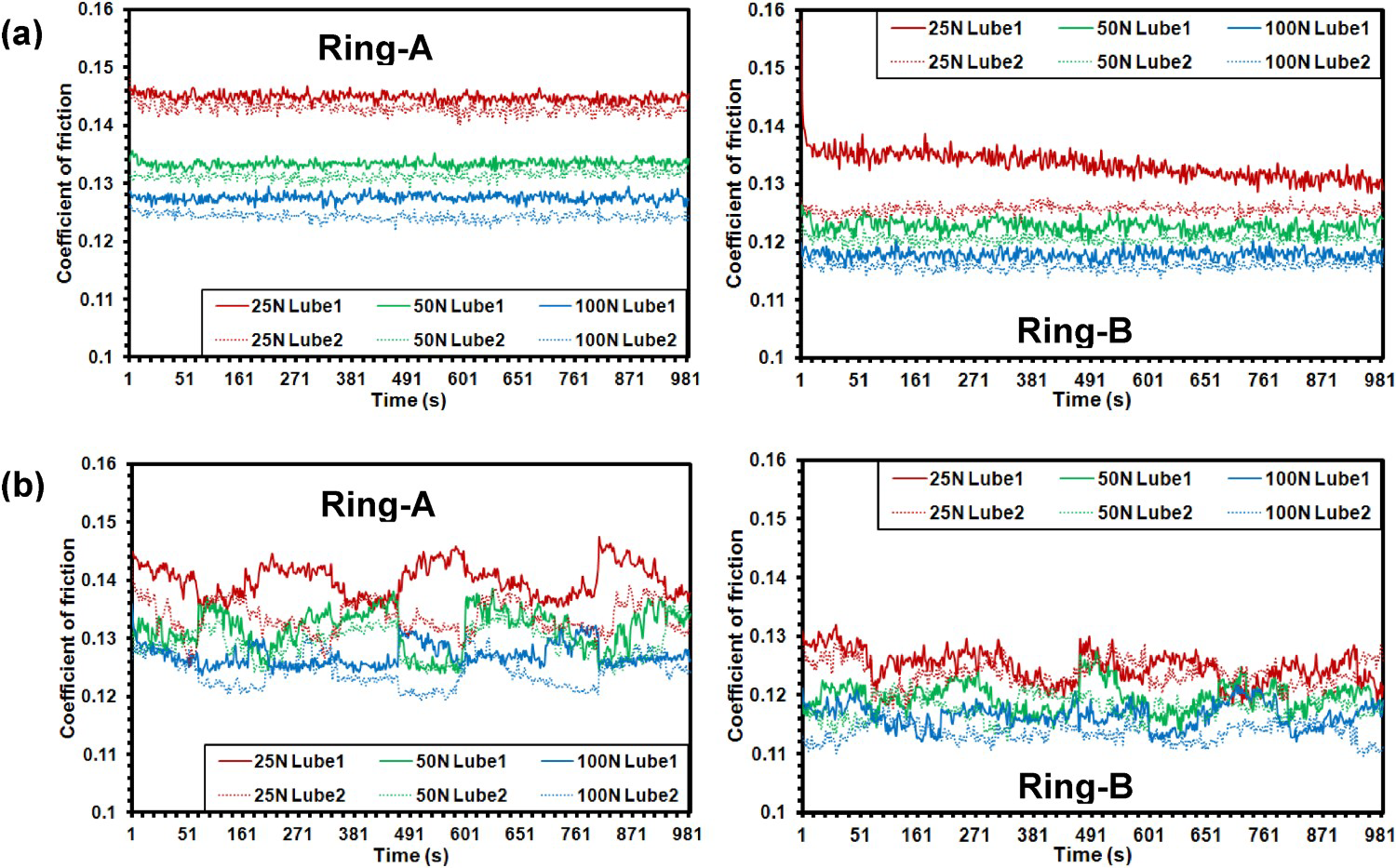
Figure 7(a,b) shows the influence of reciprocating frequency on the contact friction. It is observed that the friction decreases with increase in reciprocating frequency irrespective of the ring contact combination and the lubricant used. The increase in reciprocating frequency results into increase in speed as a result of which the contact friction decreases. It is also observed from Figure 7(a) that with the combination of lower load and frequency, the friction trace is relatively smooth. However, at lower load, the friction becomes erratic with increase in frequency. This erratic fluctuation in friction becomes slightly normalized with the combination of higher load and higher frequency.
Influence of reciprocating frequency on contact friction at load; (a) 25 N and (b) 100 N.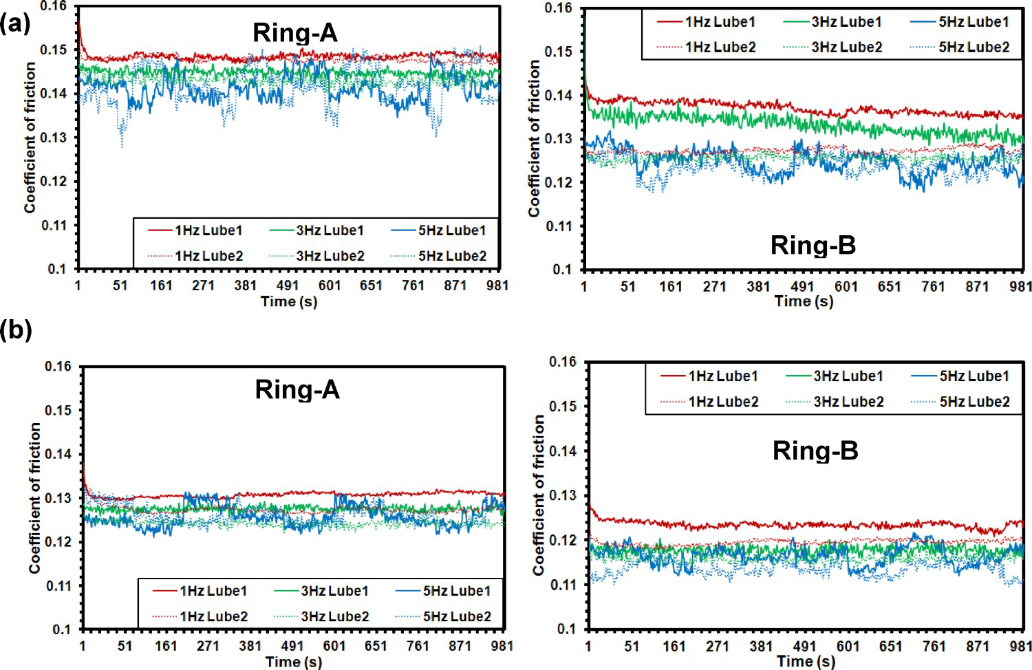
The influence of ring contact combination and the lubricant used on the contact friction is shown in Figure 8(a–c). It is observed that Ring-B results in lower contact friction than the Ring-A. Moreover, the use of Lube-2 results in lower friction compared to Lube-1. This behaviour of contact friction is consistent irrespective of the contact frequency and the load used. It is observed that at any given reciprocating frequency and applied load, the combination of Ring-B lubricated with Lube 2 results into lower contact friction. Similarly, the combination of Ring-A lubricated with Lube-1 results into a higher value of contact friction.
Influence of lubricant and contact combination on contact friction at reciprocating frequency; (a) 1 Hz, (b) 3 Hz and (c) 5 Hz.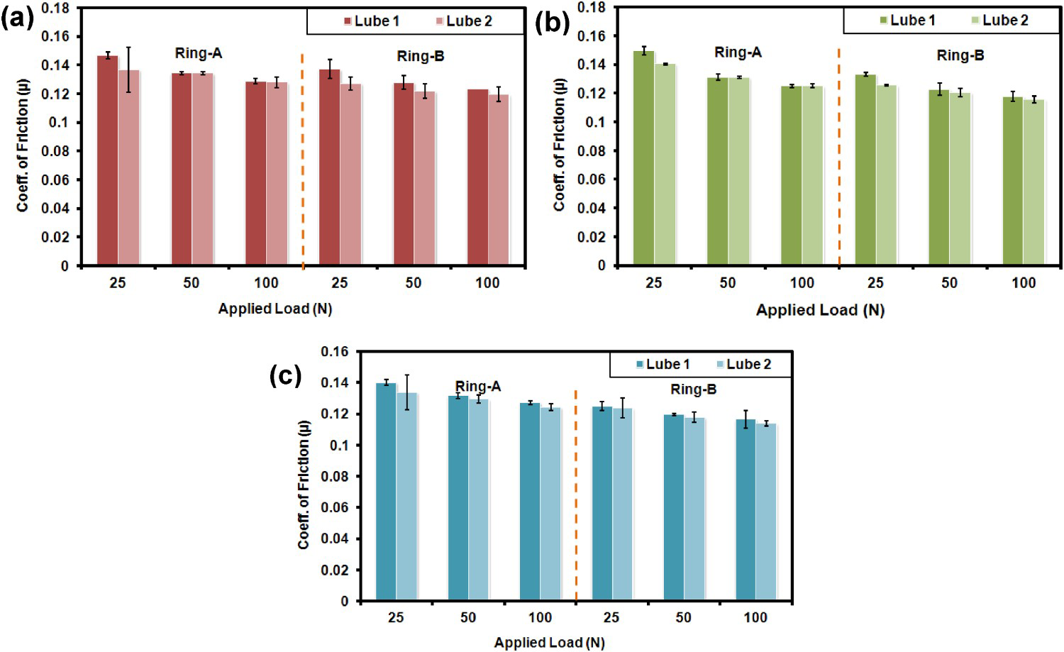
The percentage reduction in friction with the use of Lube-2 over Lube-1 for both the ring contact combinations is shown in Figure 9. The percentage reduction in friction is around 7% at 25 N load and 1 Hz reciprocating frequency. This decrease in friction reduces to around 2–3% at 100 N load and 5 Hz frequency. This suggests that an appropriate selection of engine oil can help in reducing the contact friction irrespective of the ring contact combination used.
Percentage reduction in friction with use of Lube-2 as compared to Lube-1.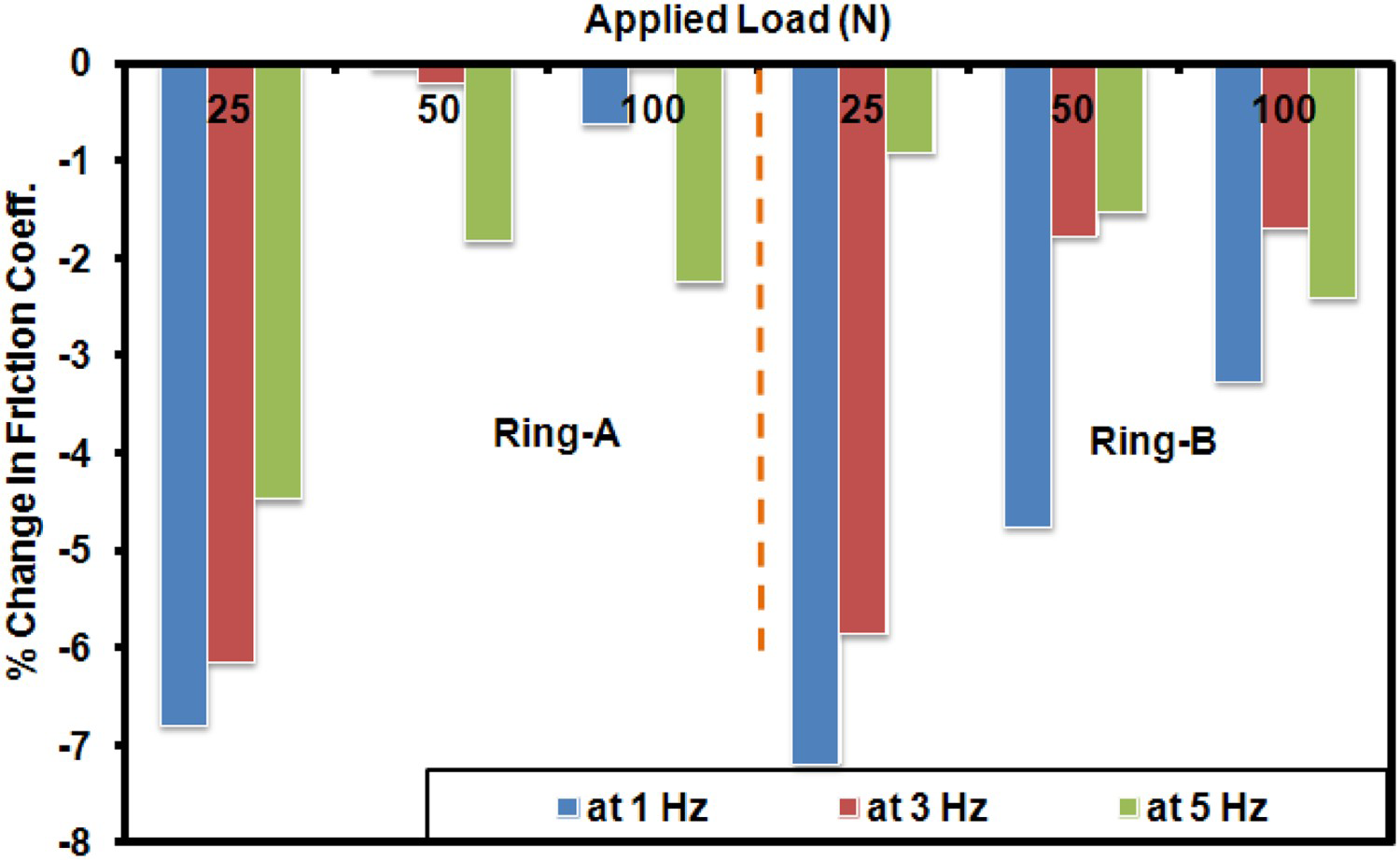
Modelling Results: The numerical results obtained from the mathematical model are used to identify the reasons for the behavioural response of the piston ring liner contact obtained from experiments. As the ring along with piston reciprocates over the liner, the possibility of metal to metal contact cannot be avoided, at the TDC and BDC. This possibility becomes prominent during the power stroke. The contact friction increases due to the metal to metal contact. The friction also increases due to the interlayer shearing of the lubricating film. Hence, with the help of a mathematical model, the lubricant film formed within the contact vicinity over the 720° of crank rotation was determined along with the contact load shared by the asperities and lubricant film. Figure 10(a–c) presents the results for the asperity contact load, oil film load and lubricant film thickness for Ring-A contact lubricated with Lube-1. The simulation results were obtained for both the ring contacts. However, due to brevity of space, only results for Ring-A are shown. The results reveal that the asperity contact pressure decreases with increase in reciprocating frequency. At 1.67 Hz, the asperity contact pressure is highest at the dead centres. The value at the onset of power stroke accounts to 0.33 N/mm which decreases with an increase in frequency. At 25 Hz, the asperity contact load is nominal at 0.02 6N/mm. Figure 10(b) shows the load shared by the lubricant film. The load shared by the lubricant film is almost the same with very minor changes in the peak values at any given reciprocating frequency. Figure 10(c) reveals that the lubricant film thickness increases with increase in reciprocating frequency. The lubricant film thickness at the dead centres is of the order of 1 µm at 1.67 Hz which increases to approx. 3 µm at 25 Hz. At the mid-stroke region sufficiently thick lubricating films to the order of 7-9 µm is observed at higher frequencies. However, at lower frequency the mid-stroke film thickness is as small as 3-4 µm. At the onset of power stoke the film thickness is around 2 µm. Hence, it can be concluded that the lubricant film thickness increases and the load shared by the asperities decreases with increase in reciprocating frequency. The load shared by the oil film remains almost the same at any given frequency. As a result of this, the contact friction decreases with increase in reciprocating frequency.
Influence of reciprocating frequency on (a) asperity contact load, (b) oil film load and (c) lubricant film thickness.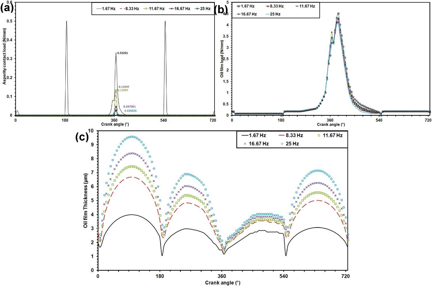
The composite surface roughness represents the RMS value of the roughness of the contacting surfaces. In the present case, the contacting surfaces are those of the piston ring and the liner. Figure 11(a–c) presents the influence of the composite surface roughness on the asperity contact load, oil film load and oil film thickness for a given ring contact combination lubricated with given oil. It is observed that the asperity contact load increases with an increase in roughness, but the increase is very nominal. The increase in roughness from 0.08 to 0.15 results in the increase in asperity contact load at the onset of the power stroke to 0.36 from 0.33 N/mm. It is also observed that the composite surface roughness has no significant influence on the oil film load and lubricant film thickness.
Influence of composite surface roughness on (a) asperity contact load, (b) oil film load and (c) lubricant film thickness.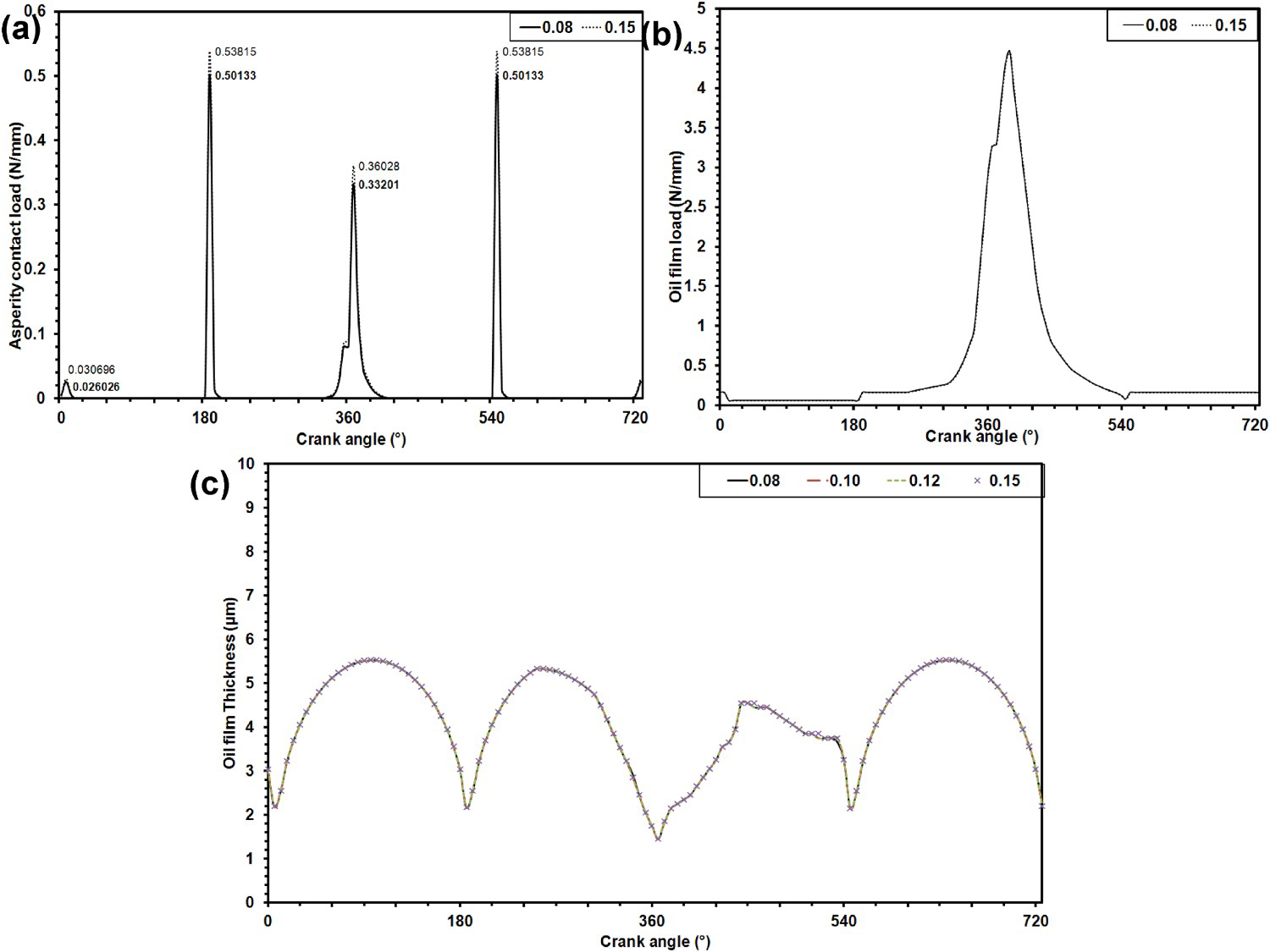
The influence of lubricant on the asperity contact load, oil film load and the lubricant film thickness is shown in Figure 12(a–c). The load shared by the asperities is highest (0.083 N/mm) in case of Ring-A contact lubricated with Lube-1. While it is lowest (0.026 N/mm) for Ring-B lubricated with Lube-2. Also the oil film load in case of Ring-B is higher as compared to Ring-A. The lubricant film in case of Lube-2 is thicker as compared to Lube-1 for any given contact. However, the lubricant film thickness in power stroke is higher for Ring-B and lower for Ring-A. As a result of this, the contact friction is higher in the case of Ring-A.
Influence of lubricant on (a) asperity contact load, (b) oil film load and (c) lubricant film thickness.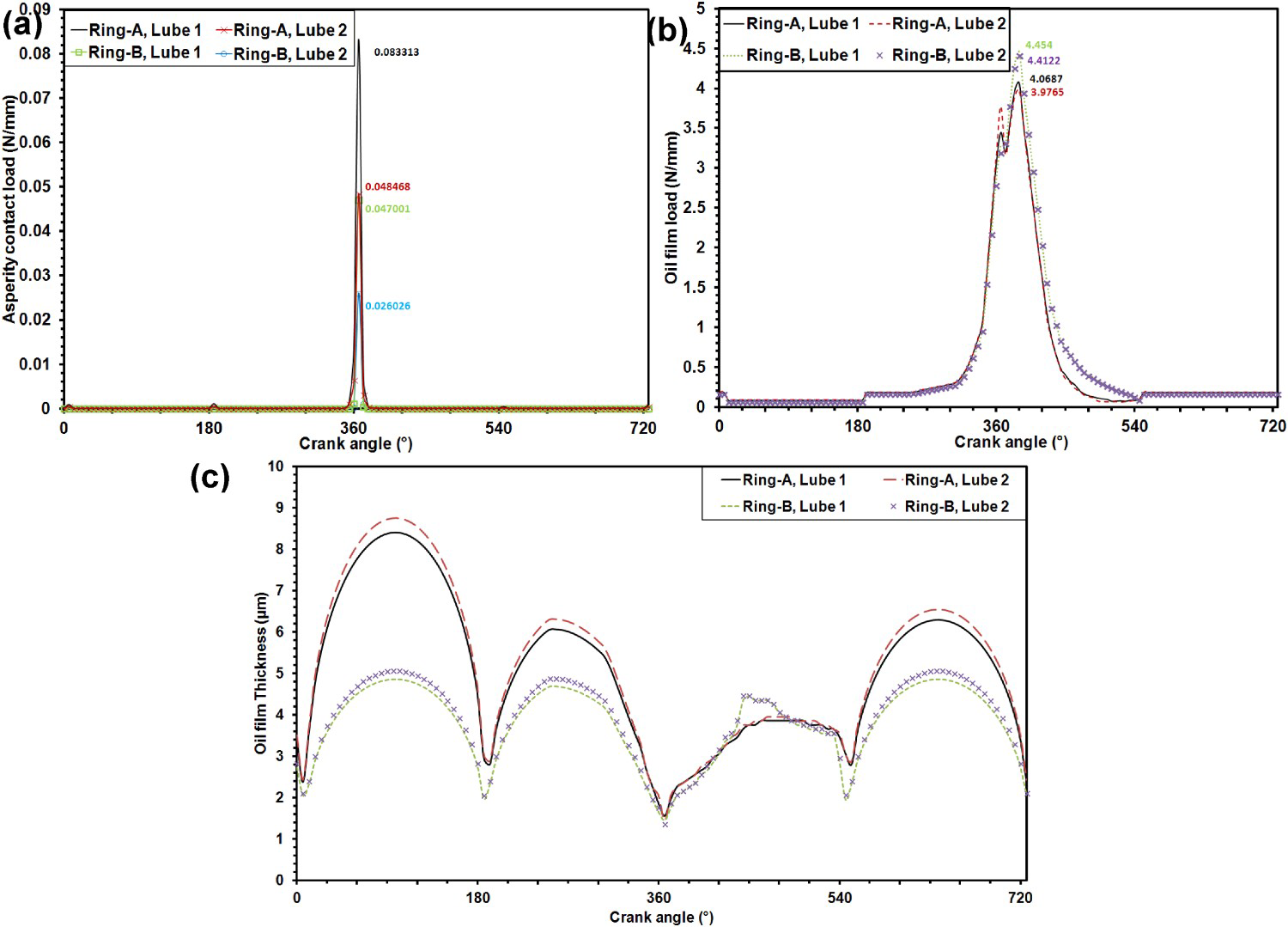
In the present study, a novel tribological approach has been used to select engine oil for lubrication of piston ring liner contact that results in reduced contact friction. The coupled experimental and numerical approach has been followed to investigate the friction behaviour. Also, the influence of operating parameters on the contact friction has been undertaken. The numerical results have been used to justify the experimental findings. The numerical model has been used to determine the contact load shared by asperities in contact, oil film load and the lubricant film thickness. On the basis of the study undertaken the following conclusions are drawn:
A numerical model using a modified Reynolds equation incorporating the flow factors presented by Morales-Espejel has been developed. The numerical simulation of model presents the lubricant film thickness, contact pressure and the load shared by the asperities and oil film. The model results are able to provide reasons for the experimental results qualitatively. The model can be further enhanced by incorporating squeeze term for more accurate results. It is observed that the contact friction for a given lubricated ring liner contact decreases with increase in reciprocating frequency and the contact load. With an increase in reciprocating frequency, the lubricant film thickness increases and the asperity contact load decreases while there is no significant change in the oil film load. Hence, the contact friction is low at higher reciprocating frequency. Among the selected lubricants, the Lube-2 presents the thicker lubricating film as compared to Lube-1. The load shared by the asperities in contact is higher in the case of Lube-1 while the load shared by the lubricant film is higher in case of Lube-2. As a result of this, the Lube-2 presents better anti-friction behaviour. Thus the study undertaken provides a clear justification for the friction behaviour within a piston ring liner contact.
Footnotes
Disclosure statement
No potential conflict of interest was reported by the author(s).