
Abstract
Copper matte converting is the key step to ensure high primary copper recovery in the smelting chain. Its development and the fundamental research carried out over the past decades will be reviewed. The operational challenges and environmental concern of batch-wise Peirce-Smith Converting vessel have induced more than 50 years ago attempts to continuous converting process which have materialised in the last two decades in the flash converting technology, utilised currently in one smelter in USA and three smelters in China. Their annual copper production is in excess of 1.5 Mt, and selected fundamental studies behind this major technological invention will be examined.
Introduction
Peirce-Smith converter of today is understood as a horizontal, rotary and cylindrical vessel lined with refractory bricks (Milliken and Hofinger 1968). The original patent of Peirce and Smith (1909) did not make major claims to the shape of the vessel, blowing direction or design of its tuyere line. Since 110 years all types of copper converting vessels lined with basic bricks (MgO) instead of silica are called Peirce-Smith converters (PSC), independently of blowing geometry. The technological development was a spin-off of the invention of Bessemer converter for steelmaking in 1855 (Allen 1979). Due to different properties of copper compared to steel, the bottom blown technologies and vertical converters were gradually abandoned (Southwick 2008).
According to a recent copper smelting survey (Wang et al. 2016), about 70% of the smelters use PSC and its modifications. This popularity comes from two main factors, obvious simplicity of operation and the capability of melting cold recirculating material (reverts) at the smelter. Its good and at the same time harmful feature is the batch operation which requires skilled operators, as the instrumentation and process control development has been slow, and it generates a large and cyclically fluctuating off-gas flow low in SO2 (Ng et al. 2005).
In spite of being a successful industrial operation there has been insufficient research in understanding fluid flow aspects of the process. Mixing and mass transfer in the converter are key process parameters that have been studied little. Due to similarity of the basic concept in ladle processing and PSC, the core aspects have been adopted for process characterisation of PSC in an effort to address the challenges in productivity (Hoefele and Brimacombe 1979; Gray et al. 1984; Vaarno et al. 1998). Physical and numerical models of PSC have been developed to study multiphase fluid flow phenomena (Liow and Gray 1990; Vaarno et al. 1998; Valencia et al. 2002, 2004, 2006; Koohi et al. 2008; Ramirez-Argaez 2008; Rosales et al. 2009; Chibwe, Akdogan, Aldrich, et al. 2011; Chibwe et al. 2012; Chibwe, Akdogan et al. 2013; Chibwe, Akdogan, Aldrich et al. 2013). These models have been used to establish functional relationships of process variables such as reaction kinetics (Kyllo and Richards 1998), injection dynamics (Schwarz 1996; Rosales et al. 1999), and fluid flow behaviour (Han et al. 2001; Real et al. 2007; Chibwe et al. 2014, 2015). Vaarno et al. (1998) and Valencia et al. (2004) evaluated the applicability of mathematical formulation to the PSC process using cold models with success and established velocity vector fields investigating the effect of Froude number on bath mixing, jet stability, and splashing.
The concept of continuous Flash Converting (FCF) process was first presented in 1983 at Sulfide Smelting Symposium. The Kennecott-Outotec Flash Converting process was taken into operation in 1995 at Kennecott's Utah Smelter in conjunction with Outotec Flash Smelting (FSF) as the primary smelting step. The use of highgrade matte offers the option of converting large amounts of copper in one process unit with major environmental and resource efficiency benefits.
Copper matte converting process
Copper smelting from sulphidic ores and concentrates is based on a stepwise oxidation of iron so that oxygen activity increases in a controlled manner, step by step. The resulting product is blister copper containing small concentrations of oxygen and sulphur. The main reactions can be written as.


In the smelting and converting, the matte composition follows roughly the FeS-Cu2S joint of the Cu-Fe-S system, which means that chalcopyrite, the most common copper sulphide mineral, depletes both sulphur and iron during processing, as reaction (1) indicates. In the primary smelting step, the gangue will be deported in the slag and as far as the furnace matte is concerned, the converting step in different smelters receives matte in relatively uniform assay as to its main components, but its Cu/Fe -ratio or matte grade varies. Thus, the converting steps involve only those components tapped from the primary smelting unit, added in scrap, reverts and flux.
The PSC is the dominant technology for final deironisation and desulphurization of copper matte from the primary smelting. The two-stage processing cycle contains several blowing and slagging periods for oxidising iron from the sulphide matte, fixed to liquid slag by pure silica or sand (Johnson et al. 1979) where slagging of copper increases substantially along the processing.
Converter fluxing practices
Copper converting slags are fluxed typically to silica concentration lower than the primary smelting slags, which contain more than 30 wt-% SiO2. Stoichiometric fayalite, Fe2SiO4 or pure ferrous orthosilicate, has a Fe/SiO2 ratio of 1.86 (w/w), i.e. total iron of slag divided by its silica concentration, and that includes a specific point where the number of bridging oxygen ions in the molten silicate network is at its minimum. Basic trace oxides affect that feature, as natural sand contains typically, e.g. alumina, lime and potassia. This point, however, is not exactly the composition which allows the most oxidising, fully molten iron silicate slag to be formed, locating in the pure FeO-Fe2O3-SiO2 ternary system at silica-magnetite (‘spinel’) double saturation with w(SiO2) = 0.272 and Fe/SiO2 = 2.04 at 1200°C, Figure 1. Basic oxides shift the double saturation point towards higher silica concentrations, and to higher oxygen activities or to higher matte grades.
Therefore, in converting the forming solid iron oxides are typically fluxed with sand to Fe/SiO2 > 2.04 (or ≤28 wt-% SiO2) so that in oxidising conditions, towards the copper blow when essentially all iron has been removed, their primary phase will be magnetite rather than silica, see Figures 1 and 2. Such conditions generate in copper converting, at low and moderate magnetite level, well behaving slags, compared to the silica saturated slags, and even form an autogenous or freeze lining on the brick lining. As Figures 1 and 2 indicate, iron silicate slags are not molten in copper-making conditions at 1200°C and in P(O2) >10−1 Pa (≈10−6 atm), but require further fluxing by copper oxide for their functioning.
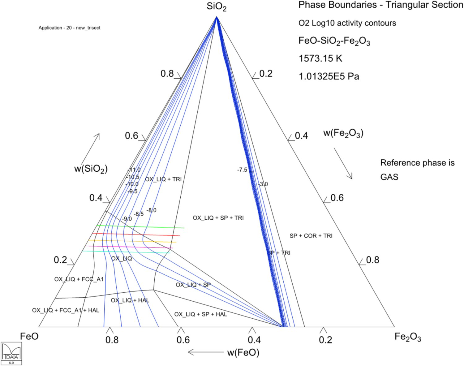
The phase equilibria and development of molten slag domain at different flux additions to pure iron silicate slags at 1200°C calculated using Mtox database (Gisby et al. 2017). Calculated isothermal section FeO-Fe2O3-SiO2 at 1200°C with oxygen isobars from 10−11 to 10−3 atm and constant Fe/SiO2 lines (w/w) of 1.6–2.4 superimposed; note ambiguity of the slag assay at a constant matte grade (∝ fixed oxygen pressure) if its Fe/SiO2 ratio is not in control, Mtox database (Gisby et al. 2017).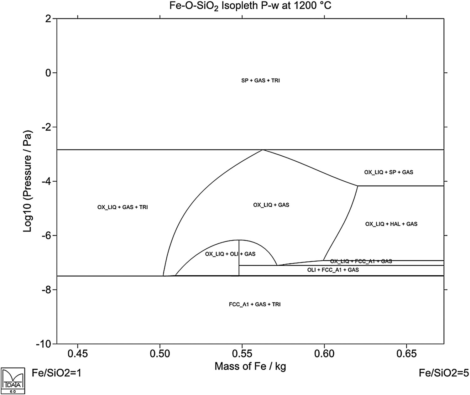
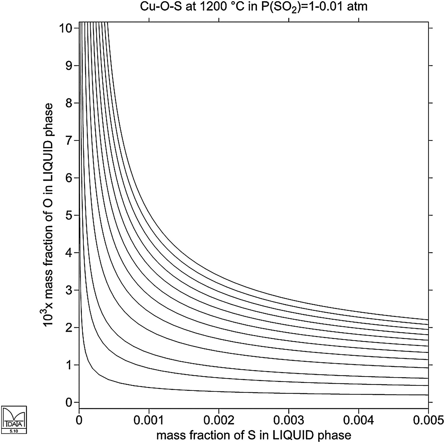
The product of converting is very low-iron, low sulphur blister copper which contains in addition to the metallic impurities chemically dissolved oxygen, depending on end point of the copper blow, according to equilibrium:
Solubility of oxygen in pure copper at 1200°C as a function of sulphur concentration in SO2 partial pressures of P(SO2) = 0.01–1 atm, in typical anode furnace conditions (Mtox 6.1 database).
Peirce-Smith converting development
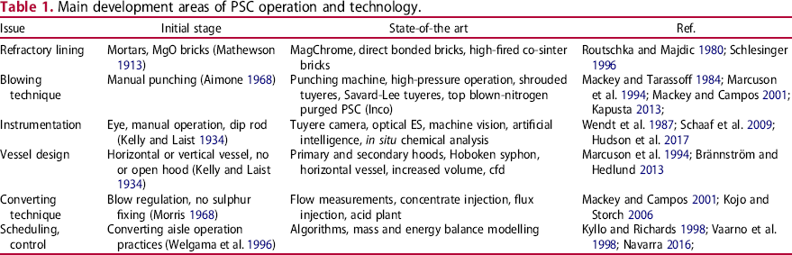
Main development areas of PSC operation and technology.
General development strands
PSC operation, including ladle transfer of matte, is today the largest single source of SO2 emissions in modern copper smelters. The enabling techniques around PSC itself include a substantial refractory material development, which first led to abandoning mortar designs for a full-brick lining constructions (Mathewson 1913), and since ‘50s, direct bonded and high-fired magnesia-chromia bricks have been in use tolerating batch-type conditions and large temperature variations of the PSC operation (Schlesinger 1996).
Poor fluxing control and variable slag chemistry, in part due to the batchwise operation, are typical to the PSC process. In many reviews, the continuous copper matte converting has been named as the target of process development for avoiding many weaknesses and practical obstacles of the PSC technology. What a continuous converting process in reality includes, has several implications in the literature? In case it involves a continuous feed of matte and continuous tapping of blister copper from the converting step that feature has been realised in a number of cases, including the Mitsubishi C-furnace, Outotec Flash converting but not in this sense in the Noranda converting, where the matte feed is not continuous.
The option of spray converting, as a promising approach to continuous converting (Sehnalek et al. 1964), was realised more than 20 years ago in a safer and highly reproducible approach of the solidified matte converting, i.e. the Outotec-Kennecott process (Asteljoki et al. 1985). Its blister copper typically contains ≈0.25 wt-% sulphur. It also allows adjustment of the fluxing chemistry in a similar way as in the primary smelting, and a flexible control of the converting end point, due to the small slag amount produced.
ICT tools and digitalisation
Proper scheduling of converter operations will not only increase the overall productivity and production rate but also is significant in terms of sulphur capture, fixing and acid plant operations (Navarra 2016). The on-line optical spectroscopy through the converter mouth (Wendt et al. 1987) has made a revolution in the end-point tracing and thus reduced hugely the chemical slag losses of copper.
The process control measures have been improved by adopting mass and heat balance simulations as off-line or on-line advisory tools for the converter operators (Kyllo and Richards 1998; Miettinen 2017). Several image analysis and in situ devices are or will soon be available for dip rod analyses and chemical assays (Schaaf et al. 2009).
Fluid dynamics of PSC operation
In spite of numerical and experimental work on fundamental phenomenon of multiphase flow, little effort has been addressed to the understanding of the combined effect of blowing rates and presence of slag phase to the overall mixing performance of the converter. Moreover, it has become an inherent process characteristic to add cold flux and scrap, process reverts and ladle skulls in order to control fluxing and temperature of the process. The solid-liquid mass transfer step may also play an important role in the performance and attainment of thermal and chemical bath homogeneity (Chibwe, Akdogan, et al. 2011). The mechanism and behaviour of dissolution of the cold additions and active sites within the converter is not well understood. Rate of dissolution is known to affect the thermal state of the converter and the turnaround time. Therefore, establishing a stable state of the converter and fully developed flow field is necessary for effective process control. Dispersion also needs further understanding, as there are quite substantial amounts of valuable metal losses due to entrapment leading to the incorporation of slag cleaning systems in the copper production circuits (Moreno et al. 2003; Warczok et al. 2003). Again, little effort has been put forward to understanding of the complex phase interactions in terms of volumetric dispersion with relation to the flow conditions.
Description of numerical and physical modelling
In this chapter, we review recent work on numerical modelling of mixing characteristics of PSC by using a physical model as basis for validation. Numerical and physical modelling of flow patterns, mixing, solid–liquid mass transfer, slag-matte phase distribution were conducted in a 1:5-scale PVC water model (Figure 4(a)) of an industrial PSC. Numerical simulations were carried out based on the 1:5 scale water model of PSC. A multi-size, variable fine mesh was employed in the matte-slag domain. The commercial CFD code ANSYS FLUENT 13.0 was used for the calculations on a High Performance Computing cluster. In order to account for multiphase nature of the flow, the VOF model was used. The interfacial behaviour of air, matte and slag was captured by a compressive discretization scheme through surface tracking of the phase interfaces in the system via solution of the VOF continuity equation. In the model, the different phases are treated numerically as interpenetrating continua. Incorporation of the effects of turbulence on the flow field inside the model was accomplished by using the Realisable k-ε (RKE) model. A coupled algorithm was used for pressure-velocity coupling. Discretisation by a Compressive Interface Capturing Scheme for Arbitrary Meshes (CICSAM) was used to obtain face fluxes, when the computational cell is near the interface using piecewise-linear approach. Velocity inlet and pressure outlet boundary conditions were used for the specification of flow conditions into the model at the tuyere inlets and open top respectively. A time step of 0.1 ms was used and found to be sufficient for maintenance of numerical convergence at every time step and stability.
Physical model of Peirce-Smith copper converter.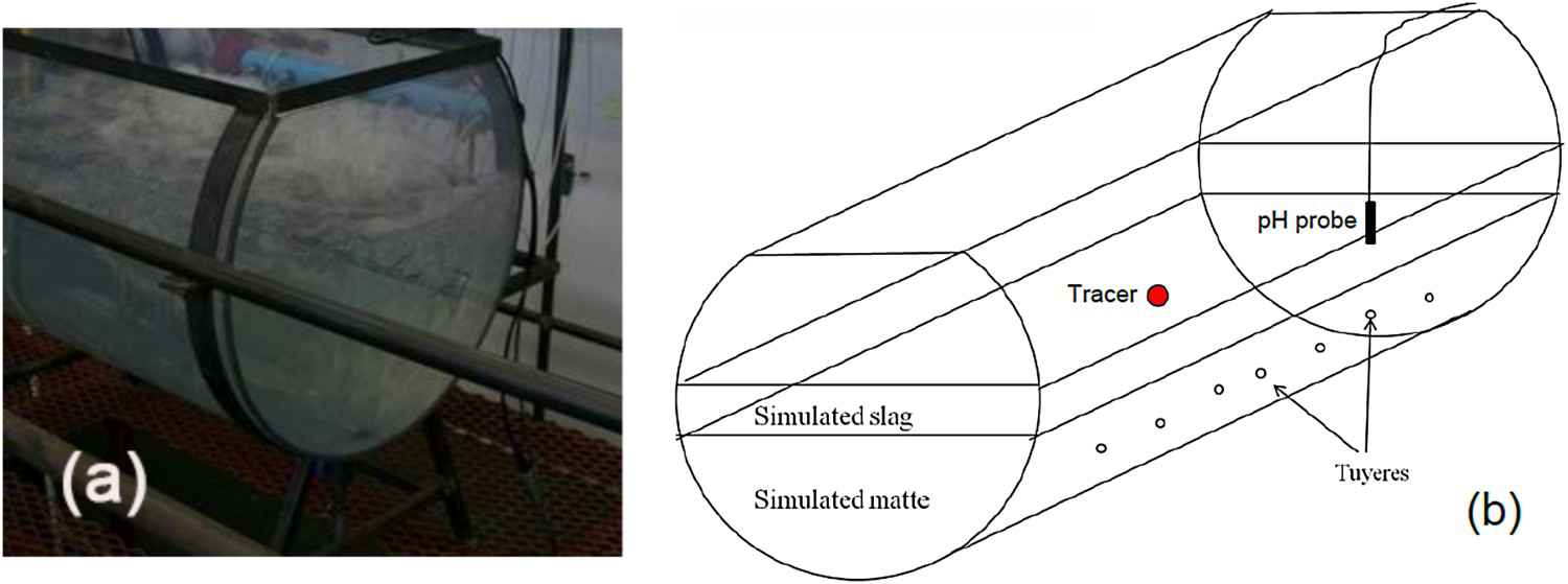
For physical modelling, Froude number was used for dynamic similarity representing fluid flow driven by inertial and gravitational forces. Kinematic similarity between PSC and model was satisfied through Morton number incorporating surface tension, viscosity and densities of the fluids. The liquid phases in the real PSC, matte and slag, were simulated with water and kerosene, respectively, for kinematic similarity. Air and sintered benzoic acid compacts were used to simulate injected gas and solid additions into the PSC. Industrial PSC and the model geometry, dimensions, fluid physical properties, and blowing conditions can be found elsewhere (Milliken and Hofinger 1968; Johnson et al. 1979). For mixing time measurements, a tracer dispersion technique with acid injection was used and monitored by a pH meter. Kerosene to water height ratio was varied from 0% to 40% at five equidistant intervals. Air volumetric flow rate was varied from 0.00875 to 0.01375 Nm3s−1, which represents typical scaled down industrial operation range. In the numerical simulations for mixing time measurements, a region was adapted in the same location as the tracer injection point where acid was patched. A custom field function formulated at the position of the pH probe, measured the mole fraction of tracer species as a function of flow time. This was achieved through solving the species transport equation. Mixing was considered complete when the species concentration reaches a stable value.
Mixing: Numerical and physical modelling
Numerical simulations revealed that in thin simulated slag thicknesses (54 mm) in Figure 5, all slag is pushed ashore, with the plume region being composed almost of matte only. This increases hydrodynamic pressure to the rising bubbles and hence increased specific energy dissipated to the liquid phase for bath recirculation due to high bubble retention time, thus increased mixing efficiency.
2-D density contour plots with 54 mm simulated slag thickness at 0.01125 Nm3s−1 (a) at 0.05 sec and (b) at 10 sec flow time.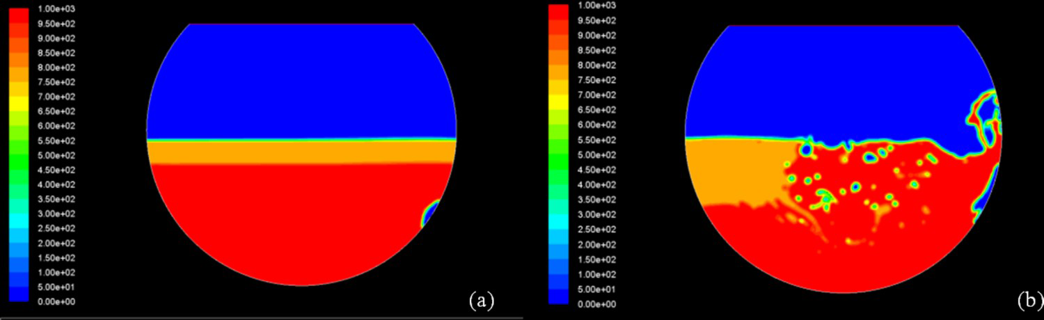
Numerical solution of flow at no simulated slag thickness (Figure 6) shows that at zero slag thickness, the power input to the system is distributed between the bulk flow recirculation and formation of splash in the plume region. With 54 mm thickness of simulated slag (Figure 5), dispersion of the simulated slag into simulated matte occur and also large splashes above tuyere line. Noticeably, the simulated slag phase is pushed ashore to the area opposite to air injection nozzles thereby forming a plume, which is mainly composed of simulated matte. Such a scenario is beneficial as it increases the tuyere bubble trajectory path and retention time for energy transfer from the bubbles to the bulk liquid before they rupture at the bath surface. However, the benefits of such retention time are offset by the effects of phase interaction, friction and diffusion mechanism, which dissipates substantial amount of energy. Also mechanisms of momentum transfer at simulated matte- slag-air interfaces fritter away potential recirculation energy. At increased slag thickness, the effect of interaction and dispersion is highly pronounced, and mixing efficiency is expected to decrease.
2-D density contour plots with no simulated slag thickness at 0.01125 Nm3s−1 (a) at 0.05 sec and (b) at 10 sec flow time.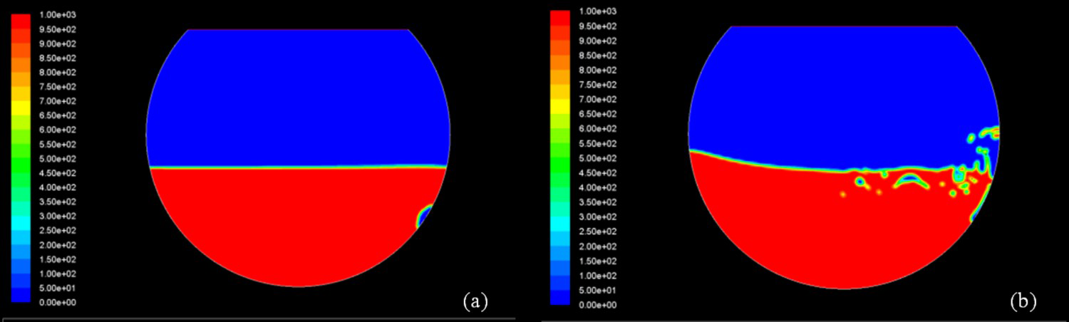
Figure 7 shows simulated matte recirculation velocity (average bulk velocity) variations with slag thickness, at constant air flow rate of 0.00875 Nm3s−1. Reduction in recirculation velocity and turbulence with increased simulated slag thickness results in decreased mixing efficiency hence an increase in mixing times. Figure 7 also depicts that substantial amount of recirculation velocity and hence turbulence kinetic energy set up in the simulated slag layer relative to the velocity in the matte. Kim and Fruehan (1987) observed in slag incorporated systems that such a large distribution of velocity in multiphase metallurgical vessels cause decreased mixing efficiency. Relative effect of velocity is more pronounced in the 108 mm slag thickness than in the 54 mm slag thickness.
Velocity vector plots for (a) 54 mm and (b) 108 mm simulated slag thickness at air flow rate of 0.01125 Nm3s−1.
Also as a comparison, numerical mixing time simulations were also done in Figure 8 with equivalent heights (351 mm) of only matte and matte plus simulated slag (81 mm). Numerical simulations with only matte depth show improved mixing efficiency. This could be attributed to improved gas bubble-bulk liquid momentum transfer due to high gas retention time, hence increased mixing efficiencies.
Numerical mixing time results for cases (a) 81 mm simulated slag thickness and (b) equivalent total simulated matte depth of 351 mm at air flow rate of 0.01125 Nm3s−1.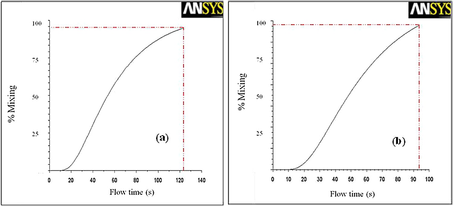
Physical modelling results also revealed that mixing time decreased with increase in specific mixing power for the cases with thin and no simulated slag (Figure 9). It is logical to assume that at no and thin slag thickness, the effect of interphase interaction i.e. interphase friction, interphase diffusion, and two-phase turbulence modification in bath recirculation, is not fully developed (Schwarz 1996), hence the reduced mixing times observed. For relatively thick simulated slag layer of 54 mm and above, this trend shifted to an increased mixing time with increase in total specific mixing power. Valencia et al. (2004) reported that an increase in air power generated more turbulence in the converter, with little benefits in terms of mixing quality in the mean flow of the bath. Therefore, the observed decrease in mixing efficiency at higher slag thickness may be attributed to three-fold effect namely; channelling, manifestation of phase interaction between matte and slag, and tuyere flow dynamics.
Effect of specific mixing power (buoyancy and gas kinetic energy) and slag thickness on mixing.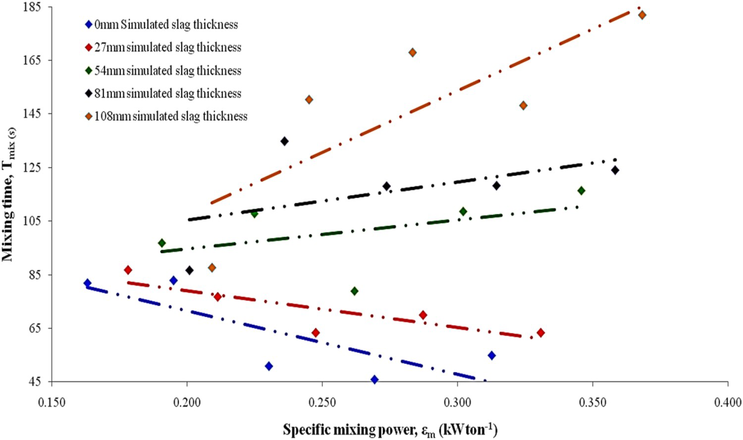
It is possible to postulate that when the melt height in the PSC is generally low, the gas channels though the bath along the vertical side wall of tuyere injection nozzle axis. In that case, residence time of the gas bubbles inside the melt is reduced which in turn will reduce gas-melt interactions within the bulk melt. As a result of channelling, the effectiveness of the gas momentum and power transfer to the bulk liquid flow is reduced. This adversely affects the mixing, liquid-liquid and liquid-solid mass transfer within the bath. On the other hand, with an increase in liquid height, the axial plume residence time increases, which results in improved interaction between the gas and liquid. This will lead to more matte entrainment into the rising plume and a stronger agitation in the bath. In order to maintain consistent mixing power and offset the adverse conditions due to rising liquids volumes, the bath height with respect to matte and slag ratio should be monitored in order to make necessary adjustments to the gas blowing rates for energy efficient process.
On the basis of the above results and discussions, there appears to be a critical slag thickness in the simulated PSC model, above which, increasing air flow rate results in extended mixing times due to a combination of channelling and secondary recirculation in the slag layer. Secondary recirculation results in dissipation of energy causing reduced bulk fluid recirculation velocity and turbulence kinetic energy. Increased matte fraction in matte/slag increases mixing efficiencies possibly due to high bubble retention. It was revealed that the slag layer as well as airflow rate has influence on the bulk recirculation velocity, turbulence and thus affecting mixing efficiency.
The flash converting process
The Flash Converting process has been presented in detail earlier (Hanniala et al. 1994, 1998; George et al. 1995; Kytö et al. 1997; George 2000; Kojo et al. 2000a, 2000b, 2000c). A short summary only is given here. A flow sheet of the Flash Converting process combined with a FSF is shown in Figure 10. Dried concentrate is smelted in the FSF using a high oxygen enrichment, allowing the smelting step to operate almost autogenously without additional fuel. The molten high-grade matte produced in the FSF is granulated by high-pressure water jets and subsequently fed into the FCF.
A typical Flash Smelting – Flash Converting process flow sheet (Outotec 2018).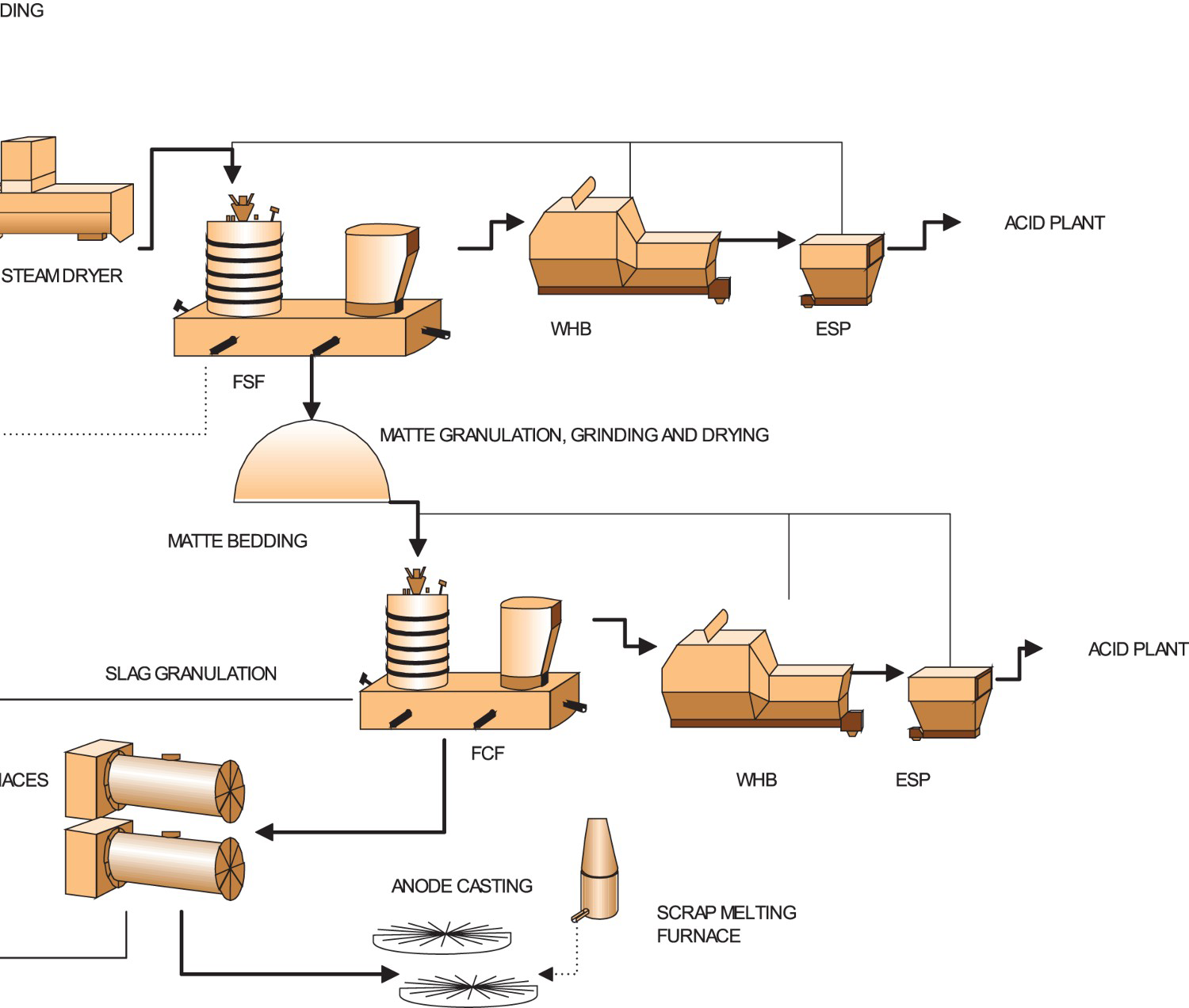
The fine-grained matte is oxidised and smelted in the FCF furnace to blister copper and slag using a high oxygen enrichment. Also the FCF can operate almost autogenously even with high matte grade feeds. The sulphur content of blister copper is controlled by the oxygen to matte ratio in the feed. Because of the small amount of slag, it will be fed back into primary FSF in granulated form and a separate slag treatment for the converter slag is avoided.
As a result of the high oxygen enrichment, the off-gas volume is small in both furnaces and rich in SO2, Figure 11. The gas flow through the cooling and cleaning steps to the sulphur dioxide recovery is continuous. The stable off-gas stream of the FCF process enables significant savings in acid plant investment costs compared to PSC. The combined gas volume of FSF and FCF furnaces is less than 80 000 Nm3/h, similar to gas volume of a single PSC (George et al. 1995). FCF produces a gas stream with much higher SO2 concentration that enables a compact off-gas line and acid plant, and low operational costs (Kojo and Storch 2006).
The required off-gas treatment capacity for producing 200 000 tpa of copper (Tuominen and Kojo 2005).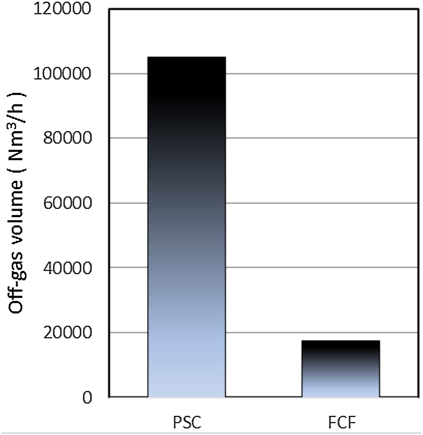
In FCF, significant energy and labour costs are saved in comparison to those of the PSC practice. Vessel availability time in FCF is significantly higher than that of a single PSC, and complete shutdown and relining is needed much less frequently. The decoupling availability of the FSF-FCF line further reduces the production time lost due to maintenance. Matte can be stored during FCF repair and the stored matte processed during FSF repair. The acid plant then operates during the entire maintenance period.
The stable bath and effective cooling of the FCF minimise the refractory wear in comparison to the intensive stirred baths, typical to PSC and lancing techniques. A typical interval for PSC relining is less than one year, whereas in FCF over five years have been proven and values close to ten years are expected. The refractory consumption per tonne of produced copper varies from 1.5 to 4.5 kg in PSC (Davenport et al. 2002), whereas in FCF it is virtually minimal, in the order of magnitude of 0.25 kg per tonne of produced copper, as shown in Figure 12.
Specific refractory consumption per tonne of copper produced in PSC and FCF (Tuominen and Kojo 2005).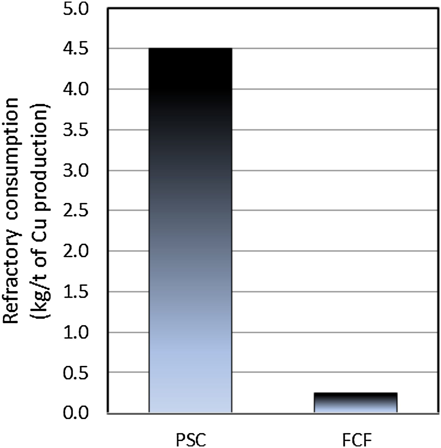
In modern FSF, the produced matte is homogeneous as to copper content (±1%). To be able to reach this, the process control has to be able to adjust to FSF concentrate quality changes, which may require variation of ± 20% in oxygen feed, see Figure 13. The FCF feed matte grade can be regarded as virtually constant. The oxygen demand variation is much lower in the FCF than in the FSF, which further stabilises the process. In both furnaces, oxygen is almost totally consumed in the reaction shaft, and a strict control is therefore possible. Copper content in the slag is the only necessary control parameter along with temperature measurements. When slag copper varies between 18 and 22 wt-%, blister sulphur varies between 0.3 and 0.1 wt-% S, respectively. The easiness of process operation enables stable operation, high online availability, stable SO2 concentration in the gas, and long campaign life.
An example of oxygen coefficient for various concentrate copper contents as a function FSF matte grade.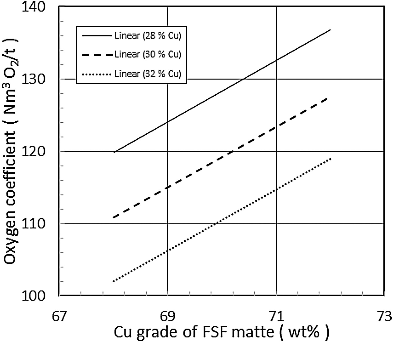
Sustainability of copper smelting and continuous converting
According to a study (Aspola 2008) the copper smelter operators valuated the following indicators to be the most important economic indicators to their operations: Operation costs, Profit/Total income –ratio, ROCE and Online time availability. All these aspects are strongly supported by continuous nature of the Flash Converting Process. In addition, the online time and especially the campaign life of the FCF can be compared to that of FSF, which is the benchmark of copper industry. One important aspect is also the economics of scale, which favour a minimal number of furnaces and process steps. This results in significant savings in both investment and operational costs.
Of the social indicators, the most important were Number of fatal accidents, Accident frequency rate and Overall working conditions. The operational safety issues and especially overall working conditions in a Flash Converting plant are on a totally different level compared to that of a plant, in which molten materials are transported to converters using ladles and cranes. In FCF, all molten materials are transported via launders, which can easily be covered for collecting the fugitive emissions. The highly automated system without ladles and high amount of fugitive gases also increase workplace safety and hygiene. High degrees of automation also decrease the labour requirements of FCF (Miettinen 2017).
Of the environmental indicators, the most important were Specific SO2 emissions, Copper recovery, Specific net energy consumption. Specific heavy metals discharges to water and Number of cases exceeding the local and/or national emission limits. These factors can be tackled most easily in a process, which collects the process gases efficiently to be treated in a sulphuric acid plant. In FCF the sulphur dioxide content of the gas is in range of 45–70 vol-% SO2 whereas in bath converting the gas strength is only 3–12% SO2. This means much higher sulphur capture, 99+ %, but also much smaller and cheaper gas handling equipment cost.
Experiences of US and Chinese FSF-FCF smelters
World's first FCF has been running in Kennecott Utah Copper for well over two decades, with an expected campaign life reaching that of FSF. After a learning period of a few years, Kennecott reached more than 5 years campaign life. Good process control together with the fact that the furnace is easy to operate will make future campaign times as long as in Flash Smelting Furnaces. During its existence, the FCF at Kennecott has processed a total of over 7 Mt of matte, i.e. about 5 Mt of copper.
Shandong Yanggu Xiangguang Copper Co. Ltd was the second copper smelter in the world to adopt the FCF technology, Figure 14. Its production started in September 29, 2007. One of the main reasons for the decision favouring Outotec FSF and FCF processes for the green field smelter in China are increasing environmental concerns. With the FCF process, sustainable operation offers the smelter an environmental license to operate for decades to come.
Yanggu Xiangguang copper smelter (Shandong, China).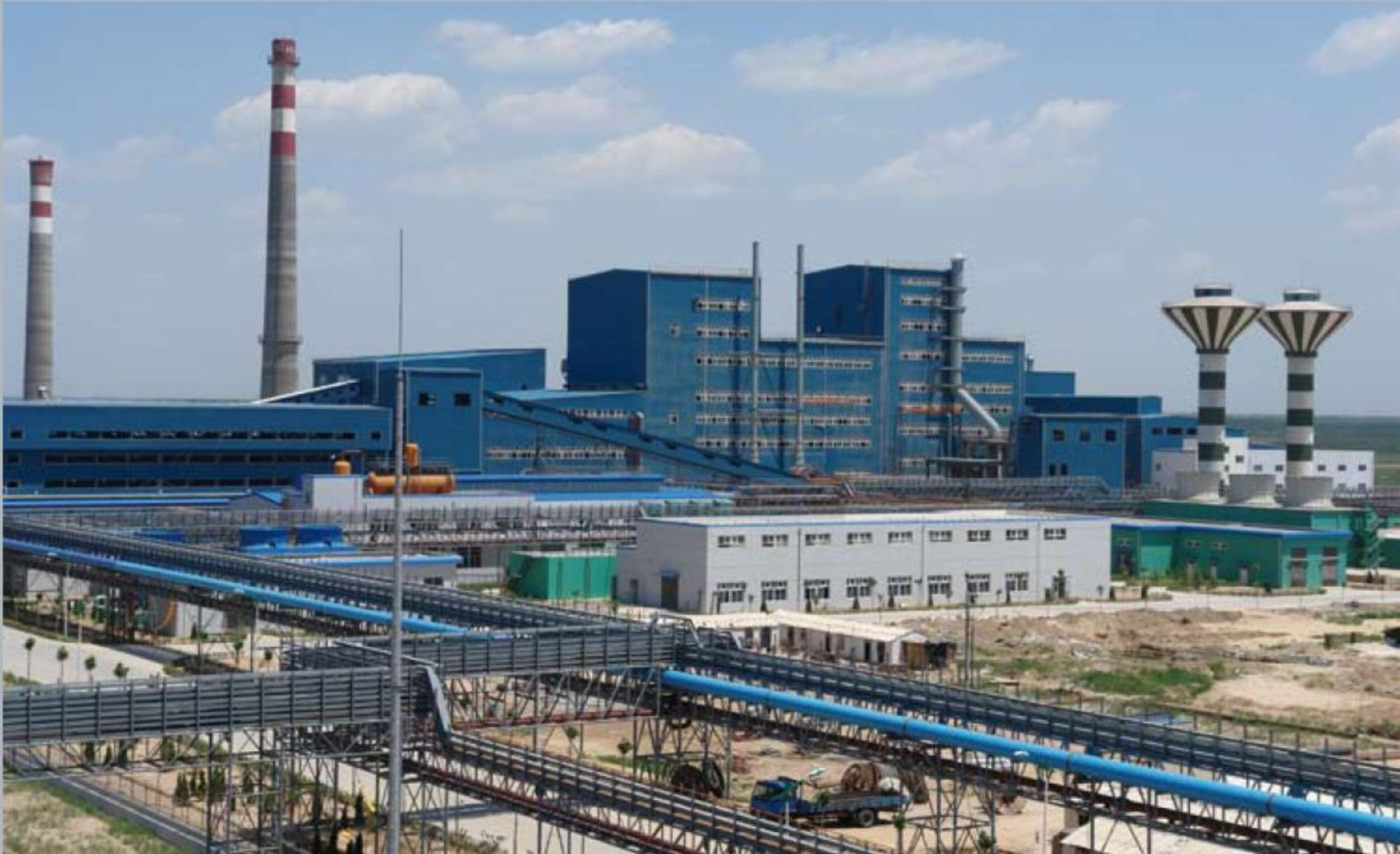
The production of the Xiangguang Copper FSF-FCF copper smelting process reached the design figure smoothly and met the standards, marking a successful application in China with only the second ‘Double Flash’ copper smelting process in the world at that time. Xiangguang's productive practice has shown that FSF-FCF copper smelting is an advanced technology and mature process. The high efficiency and environmental friendliness of the process shows also the future direction for the copper smelting. More than 3 Mt of copper has been produced at Xiangguang during the first full 10 years of the operation.
The outstanding features of energy saving, low investment and production cost, high automation and labour productivity, good potential expansion capacity and environment protection performance, and especially low flue gas pollution and SO2 fugitive emissions of the ‘Double Flash’ were also notified by the other Chinese copper smelters. The world's third FSF-FCF line was started by Tonling Jinguan Copper Corporation in January 2013 and in 2016 it reached 410 000 t annual production, more than the ‘name plate capacity’. The third FSF-FCF (in China), also with 400 000 t Cu annual capacity, the Jinchuan Fangchenggang smelter started up in 2014 and reached the design capacity in Q4 2014. In 2016 the annual production was targeted 400 000 tpa Cu. It can be said, that a Chinese standard for a large green field smelter today is a FSF-FCF line with an annual capacity of 400 000 t Cu.
Modelling the flash converting furnace
The FCF modelling is based on CFD models developed for the FSF. The main difference is in the user-defined-functions (UDF) describing the feed mixture behaviour, especially the chemical reactions and their kinetics, and particle fragmentation (dust generation). There were many attempts already in ‘70s to describe the flash smelting phenomena as a mathematical model, but we focus on more advanced models coupling chemical reactions with a Computation Fluid Dynamics (CFD) software.
From experimental kinetics and particle behaviour to numerical and CFD modelling
As one of the first developers of FS simulation by commercial CFD, prof. FRA Jorgensen and Elliot (1992) published their results on the reaction shaft simulation in 1992, and with reactions in 2003 and 2006 (Solnordal et al. 2003, 2006). The research group of an author of this article started as well in early ‘90s and published their results of fluid flow in a FSF in 1994 (Jokilaakso et al. 1994), and more advanced models with chemical reactions of feed particles for both FS and FC processes (Vaarno et al. 2003; Ahokainen et al. 2006). This model was later adopted in industrial use (Miettinen 2017). Also, Li and Xiao (2003) have published their FSF simulation results with a general purpose CFD code. More recently, also Nagai et al. (2013), Zhou et al. (2014) and White et al. (2015) have modelled industrial FSFs using the commercial CFD software ANSYS Fluent.
Over the decades, there have also been many modelling efforts, where the modelling software has been developed by the research group instead of using a commercial CFD tool. A good example of these is presented by Perez-Tello, Sohn et al. (2001), who first did an extensive experimental study of copper converting reactions (Perez-Tello, Sohn, St. Marie, et al. 2001).
Whereas the transport phenomena modelling of the FCF is based on the models developed for the FSF, the models for chemical reactions, kinetics and particle fragmentation in the FCF are based on original experimental investigations. Suominen et al. (1991, 1994) studied solid copper matte reactions in a laboratory scale drop-tube furnace. Further results were published by Riihilahti et al. (1997), Yli-Penttilä et al. (1998) and Peuraniemi et al. (1999) with dust formation in focus. Kinetics of chalcocite concentrate was, in turn, studied experimentally by Morgan and Brimacombe (1996). Developments of a kinetic model for chalcocite oxidation were reported by Ahokainen and Jokilaakso (1997) and Järvi et al. (1997).
Chaubal et al. (1989) developed a fundamental model based on thermodynamics and mass transfer processes for describing minor element behaviour in the FSF and FCF. Recently, Swinbourne and Kho (2012) developed a more advanced CFD model for minor element distributions in copper FCF.
In the experimental studies of Cu and Ni concentrates and mattes, the particles have been observed to change their size due to fragmentation, as a result of vigorous oxidation reactions (Kim and Themelis 1986; Jokilaakso et al. 1991). Perez-Tello et al. have developed mathematical correlations and a model to represent size distributions and dust formation of copper matte particles oxidised under FCF conditions in a large laboratory furnace (2002, 2008; Duarte-Ruiz et al. 2016).
Description of numerical and physical modelling
A kinetic model for FS and FC reactions describe the chemical behaviour of the feed particle in the reaction shaft conditions. In addition to the reactions, our model considers mass and heat transfer (and balance) between a particle and the surrounding gas as a function of time. The module has been coded as a separate programme to be coupled with a commercial CFD software. The CFD package solves the gas flow and particle trajectory equations, and separate source terms are defined for the interactions between particle and gas. The model described here is called the Outotec FLASH code (Ahokainen and Jokilaakso 1998).
Outotec FLASH code
The code calculates the changes in the feed particle compositions in FCF reaction shaft. The minerals included are chalcopyrite (CuFeS2), chalcocite (Cu2S), copper matte (Cu2S·yFeS) and SiO2. The particle temperature is obtained from the heat balance, which calculates the heat transfer between the particle and its surroundings by radiation and convection. It describes also the generated (or consumed) heat of the chemical reactions. The shrinking core model is used for the heterogeneous reactions between gas and the particles (Ahokainen and Jokilaakso 1997; Järvi et al. 1997). The rate controlling step is a combination of oxygen mass transfer from bulk gas to the particle surface, through the product layer to the reaction surface, and the chemical reaction. Oxygen consumption and sulphur dioxide formation is defined by the mass transfer calculation. In the FCF simulation, the solid feed mixture may contain chalcocite, copper matte, and inert phase.
Each particle type can have a different chemical composition and size distribution. The FLASH model (Ahokainen and Jokilaakso 1998) originally written for PHOENICS was later translated into CFX4. Currently, the code is implemented for the ANSYS FLUENT package, entirely with UDF. Figure 15 depicts the progress of heterogeneous reactions for a chalcocite particle by the shrinking core model. They are assumed to take place on a thin reaction interface where the overall rate of reaction is in control.
The reaction mechanism for chalcocite particle oxidation (Ahokainen and Jokilaakso1997).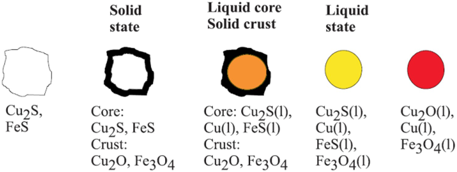
Particle-particle and particle-wall interactions
The concentrate burner of a FSF and FCF consists of several concentric ducts for the process gas and the feed mixture. It creates an optimal suspension of the solids and the oxygen-enriched process air in the upper part of the reaction shaft. Particles falling from the vertical feed tube collide to the distribution cone that turns most of the vertical momentum of the free fall to horizontal, thus ejecting the particles into the downward oriented process gas jet.
The FLASH code is based on the particle tracking algorithm of FLUENT. The standard procedure for particle tracking does not take into account any particle-particle interactions. Also, the default particle–wall interaction is not detailed enough to describe particle collisions to the distribution cone. Therefore, formation of a high particle density layer and the particle veil cannot be modelled properly, but the results over-predict the spreading of the particles into the reaction shaft, as particle-particle collisions were not taken into account.
Modelling radiation phenomena in the flash converting
Thermal radiation is the dominating heat transfer mode in every high temperature process, like the FSF and FCF. In thermal radiation modelling, the absorption and scattering coefficients in the suspension as well as emissivity of the reaction shaft walls must be included. The scattering and absorption coefficients depend on several factors, e.g. the refraction index, size, and shape of the particles. Analytical solutions exist for the Rayleigh-scattering, where particle diameter is small compared to wavelength of the radiation, and also for Mie-scattering. For large particles, the scattering coefficient is obtained by geometric optics, because scattering mainly is due to reflection.
Selected modelling results
The FS and FC are very energy intensive processes and the reaction shaft walls are under a heavy heat flux conditions from the exothermic reactions of the sulphidic feed particles, Figure 16 (Tuominen et al. 2016). CFD modelling can help in designing the concentrate/matte burner and air/oxygen flows so that the ignition and heat fluxes are optimal for the smelting operation and furnace wall cooling.
A schematic reaction shaft heat load comparison, ignition of concentrates (Tuominen et al. 2016).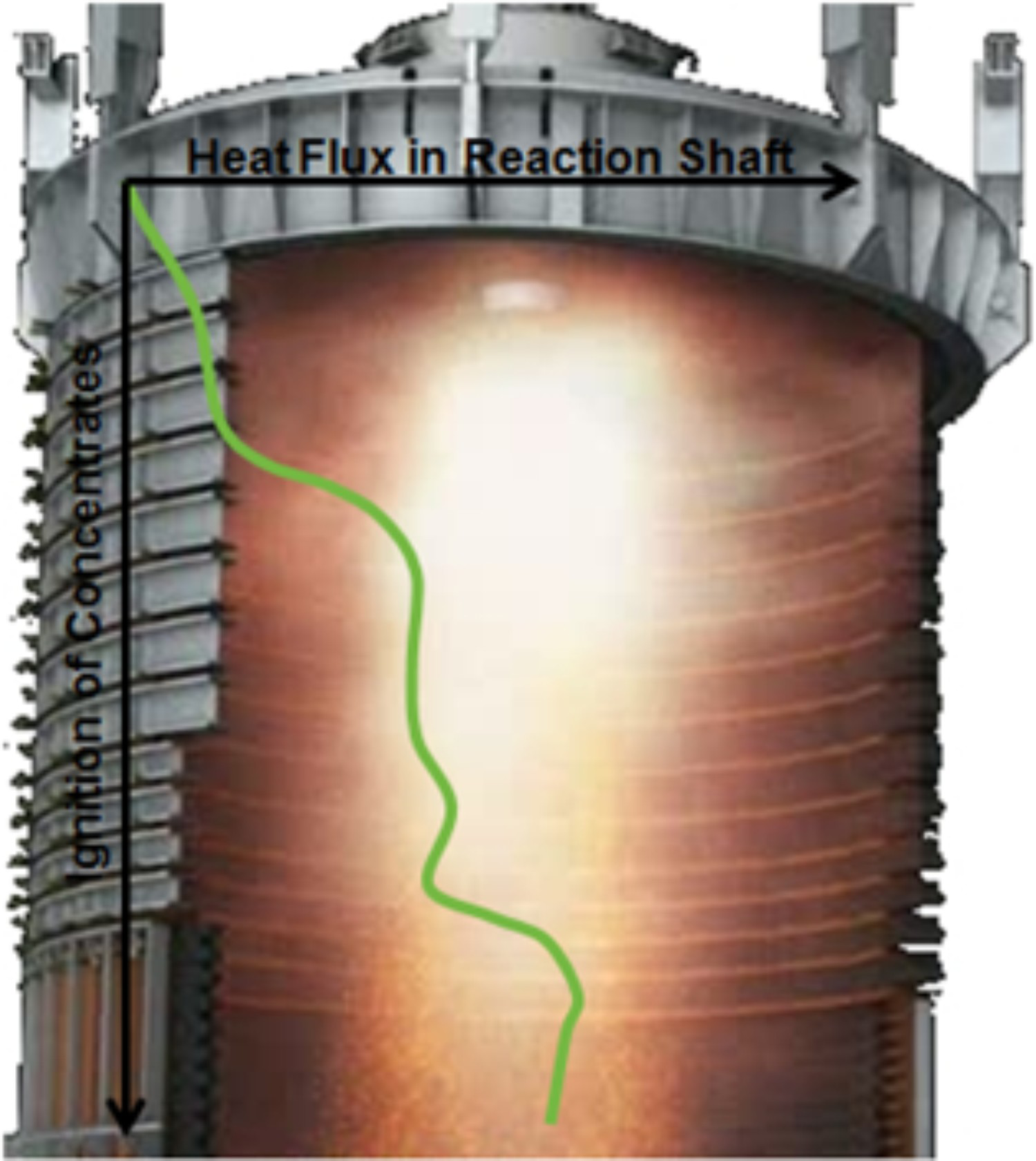
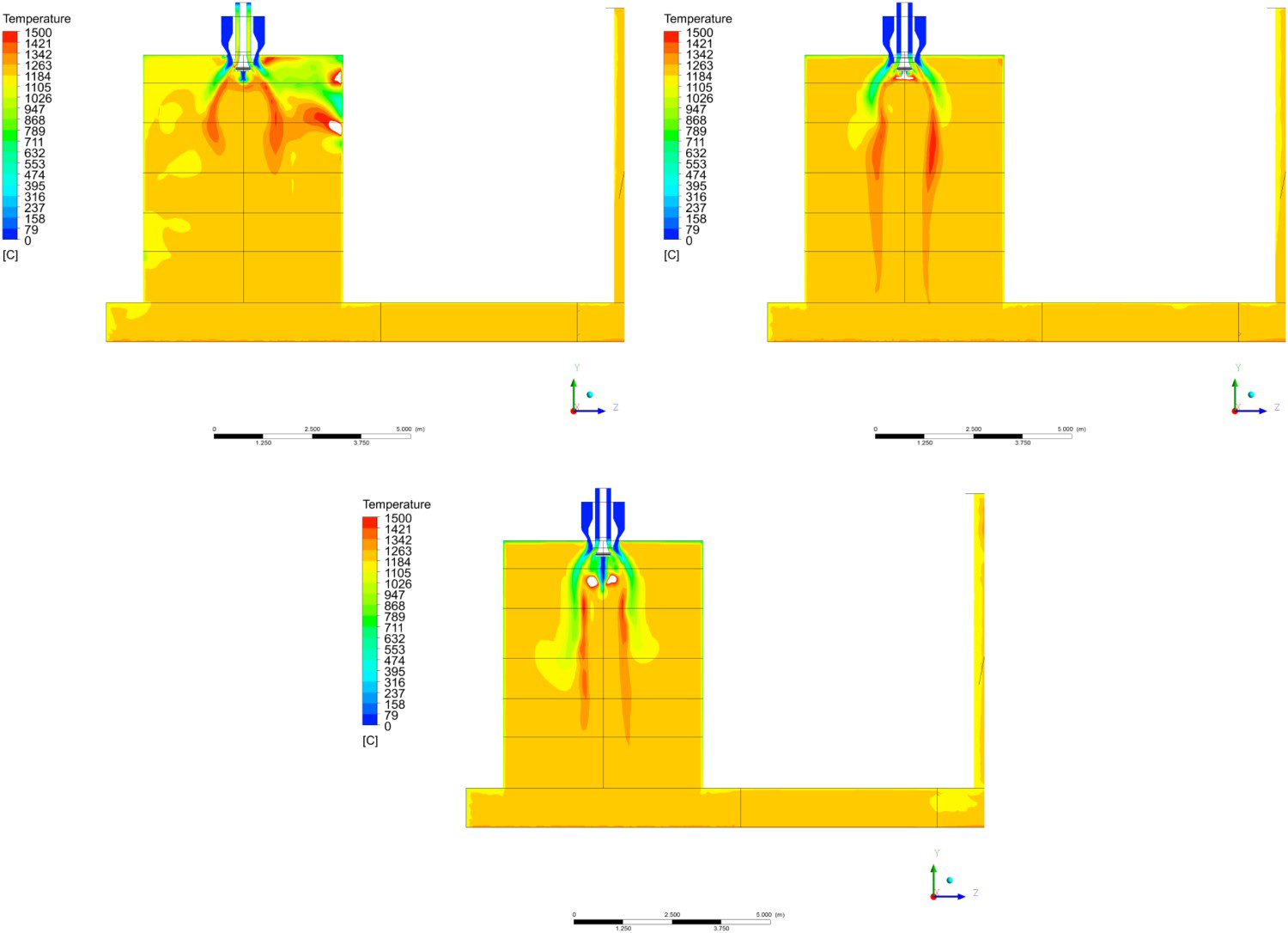
Outotec is using the FC model in several industrial cases for studying parametric changes, such as distribution air, reaction shaft dimensions, and capacity (with different operating parameters, respectively) (Outotec). Figure 17 compares particle mass concentration (kg/m3) in the reaction shaft with existing (left) and a new burner (right) design. A comparison of feed rate on temperature contours is presented in Figure 18 (Outotec 2018).
Particle mass concentration (kg/m3) in the reaction shaft with existing (left) and new burner (right) in a FCF (Outotec 2018). A comparison of the temperature field, from top to down: the base case; maximum feed; additional coolant in the feed mixture (Outotec 2018).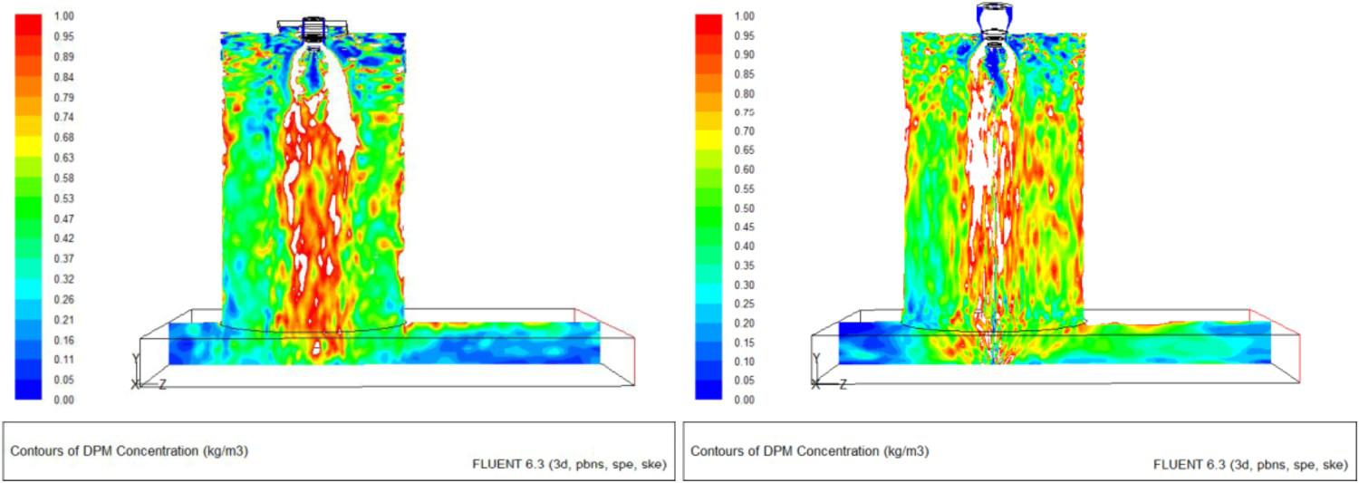
Conclusions
In the recent 2016 Copper Smelting Survey (Wang et al. 2016), out of total 110 operating copper smelters 73 report using PSC as the technology for copper matte converting. Since the 2004 JOM review (Kapusta 2004), three new continuous converting plants have been started up in China and several smelter upgrades with PSC technology as the converting step have been completed, including Bor, Boliden Rönnskär and Sar Cheshmeh, Khatoon Abad. e.g. Thai Copper and Phalaborwa have been shut down. In addition, two new direct-to-blister flash smelting plants are in operation (KCM, Głogow I) (Tuominen 2017). The recent developments in the copper industry indicate slow but steady advancement towards continuous matte converting techniques.
An apparent benefit of the disconnected copper smelting and matte converting steps is a flexible operation of the smelter where interruptions in either processing step do not stop entirely the smelting operation at the smelter line. PSC is the main consumer of cold reverts, spent anodes and external scrap in the smelter.
In green field smelter projects one small, continuously operating high-intensity converting reactor is the clear choice over several large, low-intensity vessels. Often the environmental regulations require that the least polluting process option be favoured. In the future, more stringent environmental regulations will drive the industry towards continuous converting. The possibilities for a large capacity increase without major modifications or further investment is another major benefit of the Flash Converting process. Replacing existing PSC facilities with an FSF-FCF line is a viable option for capacity increase in a sustainable and economical way. Today, FCF has shown that the environmental benefits achieved by FCF are not only benefits for the Nature but for the copper producers themselves. FCF offers comprehensive solutions for copper producers in sustainable and economical way- now and in the future.
Most disadvantages of continuous flash converting suggested by Moskalyk and Alfantazi (2003) have been proven incorrect, including the specific cases of direct-to-blister technology, and today the production capacity of continuous solid matte converting units is more than 1.5 Mtpa copper (Miettinen 2017). Since 2003, many innovative technologies in copper converting have been abandoned and vanished from industrial awareness of copper making, including e.g. QSL, WORCRA and CONTOP processes.
Footnotes
Disclosure statement
No potential conflict of interest was reported by the authors.