
Abstract
In the traditional analytical models for evaluating block toppling failure mechanisms of the slope, a single weak plane angle is assumed, running from upper rock columns and daylighting on the slope face. However, for some physical rock slopes, the weak plane bounding the potential toppling blocks may be dipping at two diverse angles within the rock masses and may not daylight on the predictable point on the face of the slope due to varying characteristics of the weak plane. The mathematical technique for estimating the counter-tilted angle of the weak plane has been proposed and incorporated into the modified analytical technique for evaluating slope stability subjected to block toppling failure. The physical slope with pre-existing weak plane dipping at two diverse angles within the rock slope subjected to block toppling was analysed using the modified analytical technique and results were validated using the discrete element method. The obtained simulated failure mode zones are consistent with those obtained by the modified analytical technique. The influence of the relative counter-tilted angles of the weak plane on slopes stability was studied and the results show that, progressive increase in the counter-tilted angles of the weak plane lead to gradual increase in slope instability.
Keywords
Introduction
Block toppling failure of rock blocks along the slope occurs when there are formed by closely spaced and steeply inclined discontinuity system dipping into the excavation.This kind of failure mode is commonly experienced in ordinary and excavated rock slopes (de Freitas and Watters 1973; Adhikary et al. 1997; Alejano et al.2006, 2010; Amini et al. 2012; Mohtarami et al. 2014). In order to enhance the stability of such slopes, reinforcing the rock columns using anchors and bolts in the toe region is a common remedial measure (Wyllie 1980). When a remedial measure of reinforcing rock slope against failure by bolting is arrived at, optimum anchor force is determined for comparative cost valuations. For this purpose, analytical analysis methods for evaluating the slope stability and determining the necessary anchor force based on limit equilibrium principles are often used. The most well-known method for evaluating toppling of rock columns was devised in 1976, by Goodman and Bray (Goodman and Bray 1976) and assumes that the unstable rock columns are bounded by the weak plane running from upper rock columns and daylighting on the face of the slope following the assumed angle of the weak plane. This method encompasses an iterative process, in which the dimensions of all the blocks and the forces acting on them are calculated, and the stability of each block is examined, starting with a set of stable blocks in the upper part of the slope, followed by an intermediate set of the toppling blocks, and ending with a set of blocks in the toe region which are pushed by the toppling blocks above. For failure to occur, the toe region must provide insufficient resistance to the resulting failure mode. Once there are some movements in the toe region, the force required to maintain the equilibrium of the slope is determined and applied at an optimum angle with respect to the horizontal plane in the toe region. If there is no movement at the toe region, the rock slope is described as stable. This analytical model ignores various external forces which have since been studied by researchers (Zanbak 1983; Aydan et al. 1989; Cruden 1989; Wyllie 1999; Amini and Majdi 2011).
Other external forces have been incorporated into the basic analytical techniques presented by Goodman and Bray to simulate the real settings that may exist. The current analytical methods have evolved into broader set of design tools (Bobet 1999; Sagaseta et al. 2001; Liu et al.2008, 2009; Zheng et al. 2017). In some jointed rock slopes, physical tests (Aydan and Kawamoto 1992; Zuo et al. 2005; Zheng et al. 2017) and field investigation results (Amini and Majdi 2011), (Cai 2013), indicate that the visible weak plane on the surface of the slope may not daylight on the predictable point on the face of the slope following an assumed angle of the observed weak plane due to variations in weak plane characteristics of the associated jointed rock slope. This entails that the observed weak plane bounding the unstable rock columns may be dipping at multiple angles within the rockmass. In such conditions, applying the current analytical approaches may not yield realistic results. The likely source of shortfalls in the current analytical approaches is related to the assumptions on the distributions of the pre-existing weak plane in the jointed rock slope.
To address this problem, a mathematical solution for determining counter-tilted angle of the pre-existing weak plane and an analytical technique that incorporates relative counter-tilted angles of the pre-existing weak plane for assessing the rock slope stability subjected to block toppling based on the limit equilibrium principles have been proposed respectively. The discussions that follow in this paper are based on the mathematical solution for identifying counter-tilted angle of the pre-existing weak plane and an analytical technique for evaluating the stability of rock slopes subjected to block toppling based on the limit equilibrium principles.
Rock slope geometry
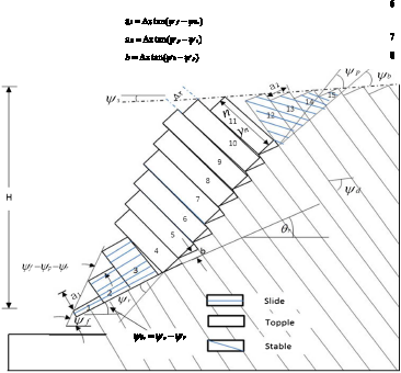
Generally, for slope stability analyses to be achieved, the dimensions of all the blocks and the forces acting on them are calculated at the initial stage. Consider the rock slope in Figure 1 that consists of rectangular rock columns with width, Δx and height, y
n
in a systematic manner. The initial pre-existing weak plane dipping at ψ
p
, is counter-tilted to ψ
θr
within the intermediate set of the toppling blocks. The height of the slope is denoted as H, the face angle is denoted as ψ
f
, while the angle of the upper slope is denoted as ψ
s
. The rock columns in the slope model are numbered from the toe increasing upwards. Results from centrifugal and numerical test models done by Adhikary et al. (1997) and Pritchard and Savigny (1990, 1991) for toppling failure mechanisms respectively, indicate that the base plane tends to be stepped during toppling failure. This has a significant influence on the overall angle of the base plane denoted as ψ
b
. In rock slopes where the weak plane has two different dipping angles, it is important to approximate the angle of the base planes (ψ
b
) using Equations (1)–(2) considering the dip angles; ψ
p
and ψ
θr
of the two inclined weak planes respectively.
Rock Slope with two different dipping angles of the pre-existing weak plane subjected to toppling failure. Images are available in colour online.

Based on the slope geometry shown in Figure 1, the number of rock columns, n, forming the regular system of the rock slope is determined by Equation (3).
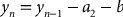
Based on the model presented in Figure 1, the height, y
n
for the nth rock column below the crest of the slope dipping into the face of the slope is determined by Equation (4), whereas if it dips above the crest of the slope, then it is determined by Equation (5).

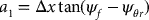
Based on the model presented in Figure 1, the constants  ,
,  and b are determined based on the rock columns and the associated geometries of the slope. These constants are determined by Equations (6)–(8), respectively;

Other typical dimensions of the rock columns required to be determined includes; the application points represented by M
n
and L
n
for the shear and normal forces (R
n
, S
n
) that acts on the two inclined weak planes and interfaces adjacent to the rock columns (P
n
, Q
n
, P n−1, Q n−1) during both toppling and sliding failure mechanisms shown in Figure 2. Whenever toppling failure mechanisms are taking place on a set of rock columns, the application points of all the forces ought to be determined. For the case where the nth rock column is below the crest of the slope, the points of application M
n
and L
n
are determined by Equations (9)–(10), respectively, when the nth block is on the crest of the slope, then the application points M
n
and L
n
are determined by Equations (11)–(12) respectively and finally when the nth block is above the crest of the slope, then the application points M
n
and L
n
is determined by Equations (13)–(14), respectively.
Limit equilibrium conditions for the failure modes of the nth rock columns: (a) forces acting on the nth rock columns; (b) toppling failure mechanisms of the nth rock column; (c) sliding failure mechanisms of the nth rock column considering the counter-tilted weak plane.


Block stability
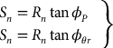
The system of rock columns bounded by the weak plane, which are counter-tilted towards the lower section of the slope is illustrated in Figure 2. In this system, three sets of rock columns are grouped based on their failure modes. In the upper section of the slope, the rock columns are classified as stable, considering that the friction angle for the weak plane bounding the rock columns is more than the dip angle of the weak plane and that the centre of gravity lies within its base. For the intermediate section of the slope, toppling failure of rock columns is more prominent, considering that the centre of gravity lies outside the base. For the toe region of the slope, sliding failure is more prominent considering that the centre of gravity lies within the base plane that is counter-tilted and block movements are in two dimensions. The modes of failure of the rock columns are influenced by the geometry of the rock columns, slope angle and angle of the weak plane. When a failure occurs, the frictional forces are generated on the bases and sides of the rock columns. The friction angles on these joint interfaces vary due to the characteristics of geological formations. Normally, for such conditions, the friction angles on the interfaces of the rock columns denoted as (ϕ
d
) are slightly lower than the friction angles on the bases (ϕ
p
, ϕ
θr
) of the weak planes. The shear forces on both sides of the rock column are resolved, using Equations (15)–(16), respectively. In contrast, the normal and shear forces acting on the rock column considering the perpendicular and sides friction angles to the two bases (ψ
p
, ψ
θr
) of a rock column with weight W
n
, are resolved using Equations (17)–(18), respectively.


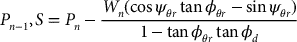
When the rotational equilibrium of rock column is considered, the force, P n−1, required to prevent failure by the toppling of the rock column is determined by Equation (19) considering the two different dipping angles of the pre-existing weak plane. If the failure mode of the rock columns in the toe region of the slope (see Figure 2(c)) is determined to be sliding, the shear force required to prevent sliding at equilibrium state is determinable by Equation (20), considering both the initial and counter-tilted angles of the pre-existing weak plane.
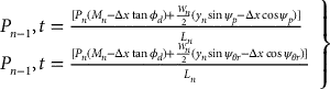
When the force (Q n−1 = tan ϕ
d
P n−1) is assumed to be acting on unknown application points L
n
and K
n
, then, the magnitude of the force, P n–1 required to prevent sliding of the block n, considering the counter-tilted angle of the pre-existing weak plane is determined by Equation (21)
Analytical technique for determining counter-tilted angle of the pre-existing weak plane
Generally, the dimensions of all the blocks are readily available for the jointed rock slopes, which are subjected to toppling of rock columns. However, for some jointed rock slopes with counter-tilted weak planes, the counter-tilted angles of the pre-existing weak plane bounding the rock columns ought to be determined. Therefore, Equation (22) has been proposed for determining the counter-tilted angles of the pre-existing weak plane by varying the basal plane with respect to the weak plane normal to the rock columns. Figure 3(a)–(c) outlines the procedure to obtain the most realistic counter-tilted angle of the pre-existing weak plane, ψ
θr
, using Equation (22).
Solving process of the counter-tilted weak plane angle, ψ
θr
. Images are available in colour online.
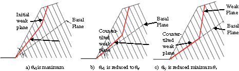
where θ rj is the angle of the basal calculation plane with respect to the initial weak plane normal to the rock columns, corresponding to calculation step j.
 is the iterative step for ψ
θr
and;
is the iterative step for ψ
θr
and;
nθ is the number of iterations for θ r .
Stabilization of rock slope by cable forces
If the calculation process described in Section ‘Block stability’ indicates that block 1 is unstable, then a tensioned cable can be installed through this block and anchored in stable rock beneath the zone of toppling to prevent movement. The design parameters for anchoring are the bolt tension, the plunge of the anchor and its position on block 1, Figure 2(c).
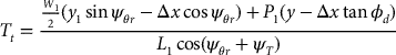
Suppose that an anchor cable is installed at a plunge angle, ψ T through block 1 at a distance L 1 above its base. To determine the anchor tension force required to prevent toppling of the rock column 1, Equation (23) that incorporates the counter-tilted angle of the pre-existing weak plane was formulated and applied. Furthermore, Equation (24) that incorporates the counter-tilted angle of the pre-existing weak plane was formulated and applied, to determine anchor tension force required to prevent sliding of the rock column 1. Once force, T is determined and applied to the rock column 1, considering the counter-tilted angle of the pre-existing weak plane, the normal and shear force on the bases of the rock columns are determined by Equations (25) and (26), respectively.


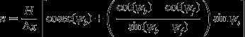
Safety factor
The safety factor of both reinforced and unreinforced slopes subjected to block toppling failure, are determined by carrying out the stability analysis based on the limiting equilibrium principle, by varying possible friction angle values until the magnitude of the force, P 0 is very small. Conversely, if rock column 1 is determined to be stable, then the friction angles are varied until the magnitude of the force, P 0 is very small. The required friction angles are defined as the limiting equilibrium friction angles, while the available friction angles are the actual friction angles of the sides of the blocks. The safety factor for block toppling can be calculated as the ratio of tangents of the available friction angles to tangents of the required friction angles as indicated in Equation (27).
The rotation of the initial weak plane ψ p is approximately equal to 2(ψ b − ψ p ), while the rotation of the counter-tilted weak plane is approximately equal to 2(ψ b − ψ θr ). This entails a conversion of the edge-to-face contacts along the sides of the rock columns into continuous face contacts and the friction angle required to prevent further rotation will drop sharply, possibly even below that required for initial equilibrium. Selection of the safety factor, therefore, depends on whether or not some deformation can be tolerated. In the field, large surface displacements and tension crack formation can be observed and yet the volumes of rock that fall from the face are small.
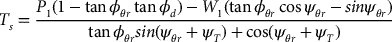
Case study-Limit equilibrium analysis of toppling failure mechanisms
Failure by the toppling of rock columns occurred in shale rock fomations on the northwall of the Nchanga Copper open pit mine located in the mining city of Chingola in Zambia in June, 2016. The copper and cobalt ore, hosted in a feldspathic quartzite formation, occurs in an interbedded sequence of roan dolostone overlain by stratigraphic sedimentary rocks namely; Chingola dolomite, banded shale rock formations types 1 and 2, upper banded sandstones, feldspathic quartzite, lower banded shale, lower banded sandstones, arkose, granite and basements formations, occurring in a series of synclines and anticlines. On the northwall limb of the asymmetrical syncline, the shale rock formations types 1 and 2 toppled into the pit (Figure 4(a)). Prior to block toppling, the slope height, H of 90 m was mined at the face angle, ψ
f
(65°) in a layered shale rock mass dipping into the face of the slope at an angle, ψ
d
(60°); the width of individual rock column, Δx is 10 m and the slope angle above the surface of the slope ψ
s
is 5°. When the pit was excavated to a depth of 85 m, cracks of less than 1 cm wide developed on the weak plane inclined at 45° from the surface of the slope. Since the planned pit depth was 300 m, the observed weak plane from the surface of the slope was predicted to daylight on the face of the slope when the pit was to be mined to a depth of 150 m. Hence, no essentials remedial measures were undertaken to prevent slope failure from disrupting operations in the pit. However, owing to variations in geological characteristics of the shale rock formations at Nchanga open pit, the weak plane inclined at 45° from the upper columns of the rock, daylighted on the slope's face when the pit was mined to a depth of 85 m. It is thought that the weak plane dipping at 45° in shale 1 rock formation had counter-tilted to 35° in shale 2 formations owing to variations in geological characteristics. This case is typical of situations that would benefit from the application of the proposed mathematical technique to determine the counter-tilted angle of the pre-existing weak plane and the modified analytical method based on limit equilibrium analysis to evaluate the stability and block toppling failure mechanisms.
Limit equilibrium analysis of a block toppling slope: (a
Calculation procedure
Based on the slope geometry presented in Figure 4(a) it is assumed that ψ
b
≈ (ψ
p
+ 10°), therefore, the approximate dip angle of the base, ψ
b
= 55°. Using Equation (3), it is determined that the slope model consists of 14 rock columns; see Figure 4(b) and that rock column 8 is at the crest. Using Equations (6)–(8), the calculated constants are  = 5.0 m,
  = 8.0 m and b = 1.0 m. The friction angles on the faces and bases of the rock columns are assumed to be equal with a value of 35° (
 ). The unit weight of the shale rock formation at Nchanga is 25 kN/m³. It is assumed that the slope is dry, and that there are no external forces acting on the slope model. The stability analysis proceeds by examining the toppling/sliding mode of each block, starting from the crest of the slope. Since cot ψ
p
= 1.0, therefore, blocks 14, 13 and 12 are stable, because for each block, the height to width ratio is less than or equal to 1.0. Thus, these three blocks are short and their centre of gravity lies inside the base. For block 11, the height-width ratio is equal to 1.6, which is greater than 1.0 and the block topples. Therefore, P 11 is equal to 0 and P 10 is calculated as the greater of P 10,t and P 10,s using Equations (19) and (21), respectively. This calculation procedure is key for assessing the stability of each block, using pre-existing weak plane angle of ψ
p
progressing downwards, up to n = 6. At block n = 5, the pre-existing weak plane is counter tilted to angle ψ
θr
thereafter ψ
θr
is substituted for ψ
p
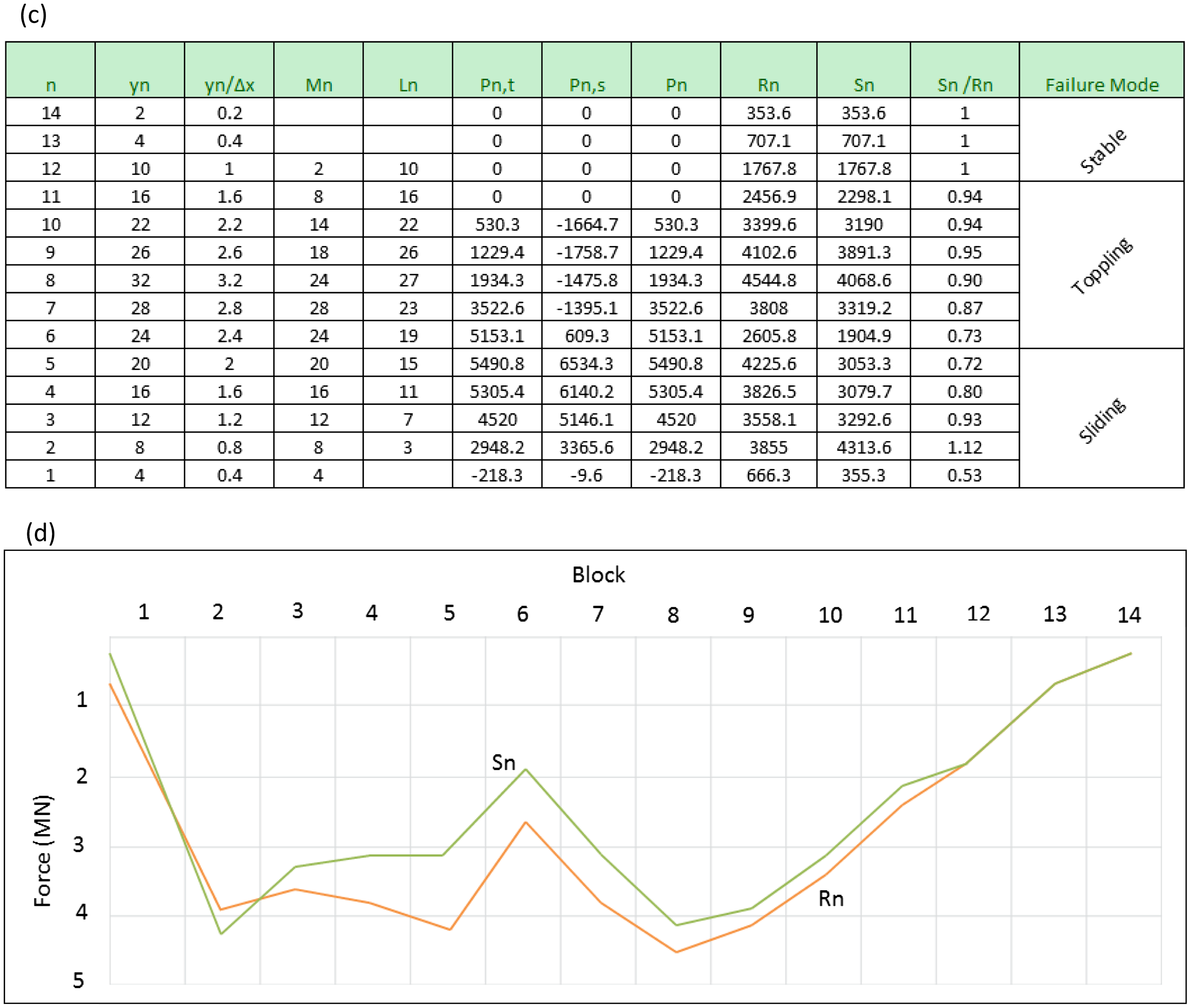
to examine the stability of each block, in turn progressing down until n = 1. The force, P n−1, t is the larger of the two forces until a value of n = 5 is reached, where upon P n−1, s is larger, as shown in the table of forces in Figure 4(c). Thus blocks 6 to 11 constitute the potential toppling zone, blocks 1 to 5 constitute a sliding zone while blocks 12 to 14 constitute a stable zone. The safety factor of this slope can be found by increasing the friction angles until the base blocks are just stable.
). The unit weight of the shale rock formation at Nchanga is 25 kN/m³. It is assumed that the slope is dry, and that there are no external forces acting on the slope model. The stability analysis proceeds by examining the toppling/sliding mode of each block, starting from the crest of the slope. Since cot ψ
p
= 1.0, therefore, blocks 14, 13 and 12 are stable, because for each block, the height to width ratio is less than or equal to 1.0. Thus, these three blocks are short and their centre of gravity lies inside the base. For block 11, the height-width ratio is equal to 1.6, which is greater than 1.0 and the block topples. Therefore, P 11 is equal to 0 and P 10 is calculated as the greater of P 10,t and P 10,s using Equations (19) and (21), respectively. This calculation procedure is key for assessing the stability of each block, using pre-existing weak plane angle of ψ
p
progressing downwards, up to n = 6. At block n = 5, the pre-existing weak plane is counter tilted to angle ψ
θr
thereafter ψ
θr
is substituted for ψ
p
to examine the stability of each block, in turn progressing down until n = 1. The force, P n−1, t is the larger of the two forces until a value of n = 5 is reached, where upon P n−1, s is larger, as shown in the table of forces in Figure 4(c). Thus blocks 6 to 11 constitute the potential toppling zone, blocks 1 to 5 constitute a sliding zone while blocks 12 to 14 constitute a stable zone. The safety factor of this slope can be found by increasing the friction angles until the base blocks are just stable.
It was found that the required friction angle for limit equilibrium conditions is 36°, so the factor of safety as given by Equation (27) is 0.96 (tan 35/tan 36). If tan ϕ is reduced to 0.577, blocks 1 to 5 in the lower section of the slope will slide while blocks 6 to 11 will topple. The tension force of the anchor cables installed at 25° through block 1, required to restore equilibrium was determined to be 100 kN per metre length of the slope. This is not a large number, demonstrating that support of the ‘Keystone’ is remarkably effective in increasing the notches of the slope stability. On the contrary, weakening the ‘keystone’ of a toppling slope, which is near failure, will have severe consequences. When the distribution of P forces is defined in the sliding region, the forces R n and S n on the base of the blocks are obtained by Equations (17) and (18), respectively. Assuming that [Q n−1 = P n−1 tan ϕs], therefore forces R n and S n can also be calculated for the sliding region. Figure 4(d) shows the distribution of the forces throughout the slope. The conditions defined by R n > 0 and |S n | < R n tan ϕ p are satisfied everywhere except for n = 2.
Numerical modelling
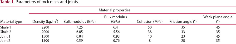
Investigations of the slope failure in the field rarely provide precise understandings of the fundamental failure mechanisms. Causes of slope failure in field study results are usually masked by the geometry and geological complexities as well as failure debris itself. Hence, accurate numerical modelling is a smart substitute for examining mechanisms of slope failure. The slope failure, conceptual model and the dimensions of the physical slope being simulated in 3DEC (Itasca 2008) are presented in Figure 4(a) and (b). The block models consist of the pre-existing weak plane inclined at 45° in shale type 1 rock formation, which is counter-tilted to 35° within the rockmass, in shale type 2 rock formations. Both shale types 1 and 2 rock are rigid materials with strength properties represented in the three-dimensional blocks. In this study, the strain-softening model that reflects a lower shear strength and null tensile strength as expected after failure was adopted. In addition, the joint constitutive model of area contact elastic/plastic with Coulomb slip failure was used to describe the discontinuities. The rock mass properties and discontinuities are given in Table 1. The numerical deformable blocks were meshed using finite difference elements.
Parameters of rock mass and joints.
Numerical modelling results
Generally, slope deformations are manifested in the form of small displacements which gradually increase until displacements begin to occur on a scale of metres after one million time steps – see Figure 5 below. The results from the numerical simulation model show gaps between the lower rock and upper rock columns which are considered as critical boundaries (1 and 2) among the failure modes. The magnitude of the displacements increased with a reduction of the internal friction angles and an increase in the time steps, until the maximum displacements occurred, predicting an apparent failure of the general rock slopes. The displacement direction appeared to be nearly vertical to the base of the rock columns with decreasing distance from the contact point to the toe. The base plane was stepped predicting that toppling deformation of rock columns was more prominent on the intermediate and upper sections of the slope than on the lower section of the slope. In the case of sliding failure, notably, interlayer slip must occur before the rock columns slide at the toe. There were no displacements in Blocks 14, 13 and 12, predicted as stable blocks.
Failure mechanisms of rock slope.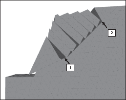
Comparative analysis – Proposed analytical and numerical modelling methods
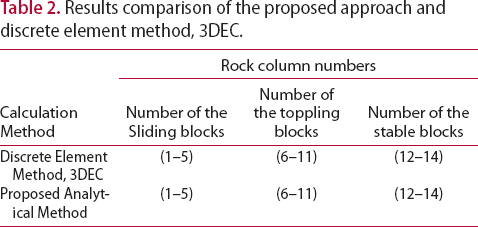
In order to obtain reliable failure modes and stability of jointed rock slopes for both methods, rock columns were analysed individually from the crest to the toe of the rock slope, which is similar to the traditional analytical methods. The zoning map, involving 14 blocks bounded by the pre-existing weak plane, is shown in Figure 5. The simulated failure mode zones were highly consistent with those obtained by the proposed analytical method considering the counted-tilted angle of the pre-existing weak plane angles. The comparison results are summarized in Table 2.
Results comparison of the proposed approach and discrete element method, 3DEC.
Influence of counter-tilted angle of the pre-existing weak plane on the slope stability
To identify better the underlying failure mechanisms contributing to failure of the slope and understanding the influence of relative counter tilted angles of the weak plane on the slope stability, six numerical simulation models with varying counter-tilted angles of the weak plane (ψ
θr
= 0°, ψ
θr
= 10°; ψ
θr
= 20°; ψ
θr
= 25°; ψ
θr
= 30°; ψ
θr
= 35°) were conducted using 3DEC software (Itasca 2008). The deformation on the rock slope manifested in form of rock column displacements. The model results show that, the progressive increase in the counter-tilted angles of the weak plane lead to gradual increase in the displacements of the associated rock columns of the rock slope see Figure 6((a)–(f)). This is highly consistent with results obtained by the modified analytical method presented in Figure 4(c). Moreover, the boundaries of the failure modes are more visible among the rock columns as the counter-tilted angles of the weak plane increase, see Figure 6((a)–(f)). Therefore, the larger the counter-tilted angles of the weak plane, the more the rock slope is prone to toppling failure. During the simulation process, as a rock column that is undergoing toppling failure mode approaches the counter-tilted weak plane, there is a possibility that the rock column undergoing failure by toppling, will transform into sliding failure mode. The change of failure mode from toppling to sliding is attributed to the change of the centre of gravity that lies outside the base of the rock column to lying inside the base of the rock column. Therefore, discrepancies of the failure modes between toppling and sliding in the intermediate rock columns were influenced by variations of counter-tilted angles of the weak plane.
Failure State due to variations of the pre-existing weak plane angles: (a) ψ
θr
= 0°; (b) ψ
θr
= 10°; (c) ψ
θr
= 20°; (d) ψ
θr
= 25°; (e) ψ
θr
= 30°; (f) ψ
θr
= 35°).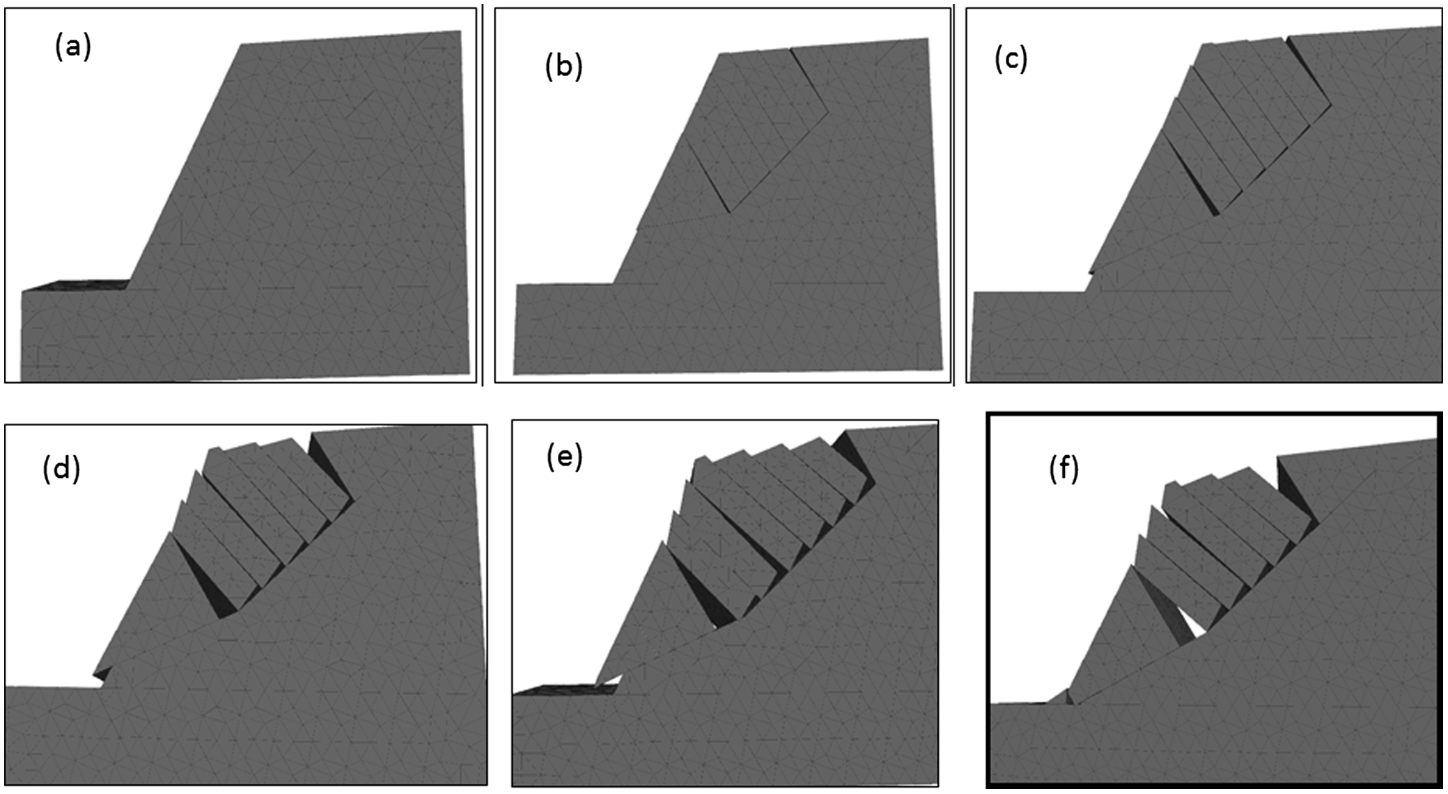
Conclusion
In some physical rock slopes, pre-existing weak planes bounding the potential toppling rock columns may be dipping at two different angles within the rock masses and may not daylight on the predicted point on the slope face due to variations in geological formations and pre-existing weak plane characteristics. Therefore, applying the current analytical techniques in such conditions may not yield realistic results. A mathematical solution for estimating the counter-tilted angle of the pre-existing weak plane has been proposed and incorporated into the modified analytical technique for assessing the rock slope stability based on the limit equilibrium principles. The physical slope with the pre-existing weak plane dipping at two different angles was comprehensively analysed using a proposed mathematical solution for estimating the counter-tilted angle of the pre-existing weak plane and the modified analytical technique based on the limit equilibrium principles and results were validated using the discrete element numerical simulation method. The obtained simulated failure mode zones are consistent with the failure mode results obtained by the modified analytical method. This confirms the validity of the modified analytical model for stability analyses of toppling rock slope with pre-existing weak plane dipping at two different angles. The influences of the relative counter-tilted angles of the pre-existing weak plane on the slopes’ stability were studied and the simulation results show that, the progressive increase of the counter-tilted angles of the pre-existing weak plane lead to gradual increase in slope instability. It was further noted that the current analytical models, overestimates the rock slope stability for the rock slopes with a pre-existing weak plane that dips at two different angles. The proposed analytical methods could curtail errors incurred due to the assumptions of the single dipping angle of the pre-existing weak plane for slope stability analyses of toppling rock slopes with pre-existing weak plane that dips at two different angles. Thus, the study presented in this paper has practical importance and could improve predictive scenarios in toppling rock slopes with two simplified weak plane angles.
Limitations
The distributions of the pre-existing weak plane adopted in this study are limited to two different dipping angles, namely initial pre-existing weak plane angle and counter-tilted angle of the pre-existing weak plane. Therefore, the results yielded are based on the assumed dipping angles of the pre-existing weak plane for the toppling rock slopes. For some physical rock slopes, the dipping angles of the weak plane are often very complicated and may not be able to be simplified into one or two dipping angles of the pre-existing weak plane. Therefore, future research on detailed analytical methods for determining complex dipping angles of the pre-existing weak plane for some physical rock slopes is recommended.
Disclosure statement
No potential conflict of interest was reported by the authors.