
Abstract
Due to the complex and dangerous nature of underground industrial sites, there is an urgent need to improve practical teaching abilities. In this paper, a VR-based interactive teaching and practice environment is proposed for teaching mining equipment processes under laboratory conditions. This environment integrates a digitised design, a virtual simulation platform, and a VR interactive product operation. This VR interactive environment includes the structural cognition of mining equipment, the actual operating conditions, and the actual operation of electronic control. Moreover, this system integrates a series of virtual reality human–machine interaction hardware, so that the students can quickly learn the operating conditions and the states of the actual underground production. This system helps them comprehensively learn the mechanical, electrical, communication, control, and mining methods involved in the mining equipment. Finally, this system provides a virtual practice path for training innovative engineering technicians.
Keywords
Introduction
Industry 4.0 aims mainly at building bridges between the digital world and the physical world. Virtual Reality (VR) technology, which is one of the key technologies, provides deep-seated technical support to people, industry, agriculture, and other fields. In addition, it promotes the development of various industries towards digital intelligence (Simone et al. 2016; Guo et al. 2020). Moreover, VR has brought substantial innovation to traditional training and teaching.
In recent years, a series of virtual environments that can support product training and teaching have been developed. Using touch, sound, and vision, virtual simulation experiments were conducted and immersive virtual environments were created for various applications, such as industrial control (Amirkhani and Nahvi 2016), industrial virtual assembly (Wei and Zheng 2016), robot operation simulation (Shamshiri et al. 2018), equipment maintenance process design (Simone et al. 2016), and safety escape during an emergency (Lin et al. 2019). Furthermore, Liang (2012) developed a full-space system for immersive VR Automotive Driving Learning (imseADL), which was then expanded to the network collaborative design environment. This latter can evaluate different indicators, such as the collision, the driving stability, and the safety while driving.
Human–computer interaction (HCI) in VR is more important than immersion (Buck et al. 2018). To this end, Vitali and Rizzi (2018) developed a customer's tail measurement for a 3D clothing design using the Kinect sensor, the Leap Motion controller, and the Oculus Rift, as well as the open-source library Visualisation Toolkit (VTK) and Qt, Moreover, the whole simulation process has been completed, from human clothing collection to clothing modelling and simulation. Bordegoni and Ferrise (2013) built a virtual environment integrating vision, touch, hearing, and other modes of HCI based on customer requirements; the proposed model allows to perform digital product delivery. In the teaching process of digital chemical plants, VR technology has gradually changed the display form of factory production. The VR technology can perform three-dimensional visualisation of the industrial production machinery and equipment operation status at the level of, the data monitoring of the working conditions, the product assembly, and the debugging links. This procedure allows to clearly present the production scene to people (Francesco et al. 2013).
However, in the mining field, the working environment is harsh, and the production process is complex. In addition, life cycle teaching products require urgent help from VR technology, with the ultimate goal of digitising the whole mine (Stothard et al. 2019). Tichon and Burgess-limerick (2011) applied VR technology in the safety training exercises for mine workers, which effectively improved their safety awareness level. Pedram et al. (2014) analysed and evaluated the underground hazards using, as well, the VR technology. Furthermore, Stothard and Laurence (2014, 2015) also designed a VR-based coal industry training simulator to let miners experiment the consequences of wrong decision-making and learn lessons.
In virtual human–computer interaction (VHCI), Grabowski and Jankowski (2015) used a head-mounted display (HMD) and different fields of view (FOV) to conduct a VR drilling operation for miners. Moreover, Foster and Burton (2013) used HMD and other interactive means to conduct a training on the remote operation of underground continuous mining and drilling machines. In addition, Akkoyun and Careddu (2015) developed a visual interactive simulation application software that integrates drilling, blasting, excavation, transportation, and washing while taking into consideration, the geological aspects. Finally, Zhang (2017) developed an intuitive VR training system for mining based on HMD.
Although the VR technology has been fully applied in the teaching process of products related to mining, the above-mentioned analysis demonstrates that:
the VR technology is mainly applied in training and teaching, especially in the industrial field; however, it is designed only to perform a single function, stage, or process, and it lacks the creation of a virtual environment for the product teaching; the VR content mostly uses offline simulation; thus, the authenticity of the simulation cannot be guaranteed because of the lack of interaction with the real data; the applications of HCI and immersive environment in the mining virtual environment are limited, which requires further exploration.
The mining equipment includes heavy machinery, and it is often used in environments with bad working conditions. In terms of teaching, the design and the development personnel should have a deep understanding of the product structure, the actual working process, and the operating conditions (Li et al. 2021). However, in fact, it is difficult to test the actual working status of the mining equipment for a long period, due to the complex, dangerous, and unpredictable production site. This results in a serious separation of the equipment operations teaching and the actual working conditions. Therefore, repeated recalculations and continuous changes are required. As a result, the expected outcome is often not achieved (Jiao et al. 2022). Thus, in the teaching phase of the mining equipment, it is highly important to fully consider the actual operating conditions, quickly identify the problems in equipment operation and maintenance, and validate the actual working conditions at the early stage of testing.
Therefore, based on the existing intelligent design theory (Xie et al. 2022a) and the visual virtual scene construction technology of the mining industry (Xie et al. 2022b), this paper proposes a virtual design environment that integrates the product digital design, the virtual simulation, the virtual and the real interactive product operation, and the machines’ maintenance. The proposed environment runs through the whole life cycle of the equipment, and it aims to solve the problems related to the whole process of mining equipment teaching. This study will allow to access the real data to simultaneously perform product simulation and product teaching, so that coordination can be achieved in the design, manufacturing, operation, maintenance, and other stages. A series of VHCI hardware is featured, allowing the designers to complete the product teaching in the virtual design simulation environment by immediately testing the operating conditions and the status in the actual underground production, and executing the actual operation and maintenance. All these tasks provide a direct and visual sense of the scene and a novel model for product teaching.
Overall framework
The traditional teaching of mining equipment mainly relies on text books and two-dimensional drawings found in the reference books. It aims at allowing the students to master the knowledge of the mining equipment structure, its operation and maintenance, and its electric control, as well as the equipment group process operation. Through the cooperation with the industry and the universities, our laboratory has established a mining equipment test system which helps the students’ experiments. However, the developed system still cannot achieve the desirable results. The main problems are summarised as follows:
The mode of the textbooks and the test system is far from the underground mining production site. The gap is specifically manifested at the level of the length of an underground production site that is approximately 200 m, and the number of set equipment that exceeds 150. The laboratory simulation test system has established a length of only 30 m, with more than 20 equipment. In addition, the test system does not have an underground related environment, the equipment is not easy to disassemble, and the internal structure cannot be seen. As for the electrical control elements, they can only be seen but cannot be performed to related interactive operation experiments.
Therefore, long-term efforts have been made to integrate the VR technology with mining teaching to achieve better teaching results.
Application process
The mining virtual interactive environment aims to provide users with an immersive experience. Through different levels of hardware interactive equipment, mining equipment is mounted from design to motion simulation verification where the operation and the maintenance of VR mapping are fully supported, as shown in Figure 1. The application process is summarised as follows:
Using the HMD which provides a real visual effect, a realistic test environment is created and interaction is performed with the relevant laboratory digital design resources, so that designers can immerse in the virtual environment and achieve the digital design of the equipment; The designed equipment is first imported into the whole process of virtual mining, and a virtual environment integrating both man and machine is established; thus, all the equipment can work together. The Vive helmet is worn to enter the virtual world for a comprehensive evaluation and to give a real scenario of the full operation; A connection is made with the actual working face equipment data and the designed virtual environment. In addition, a real-time VR mapping interaction is conducted, some remote inspection and maintenance are performed, problems are identified in the operation process, and then the VHCI hardware is used for remote operation intervention. This scenario will allow the operators to efficiently master the actual operation status of the working face in real time. System architecture.
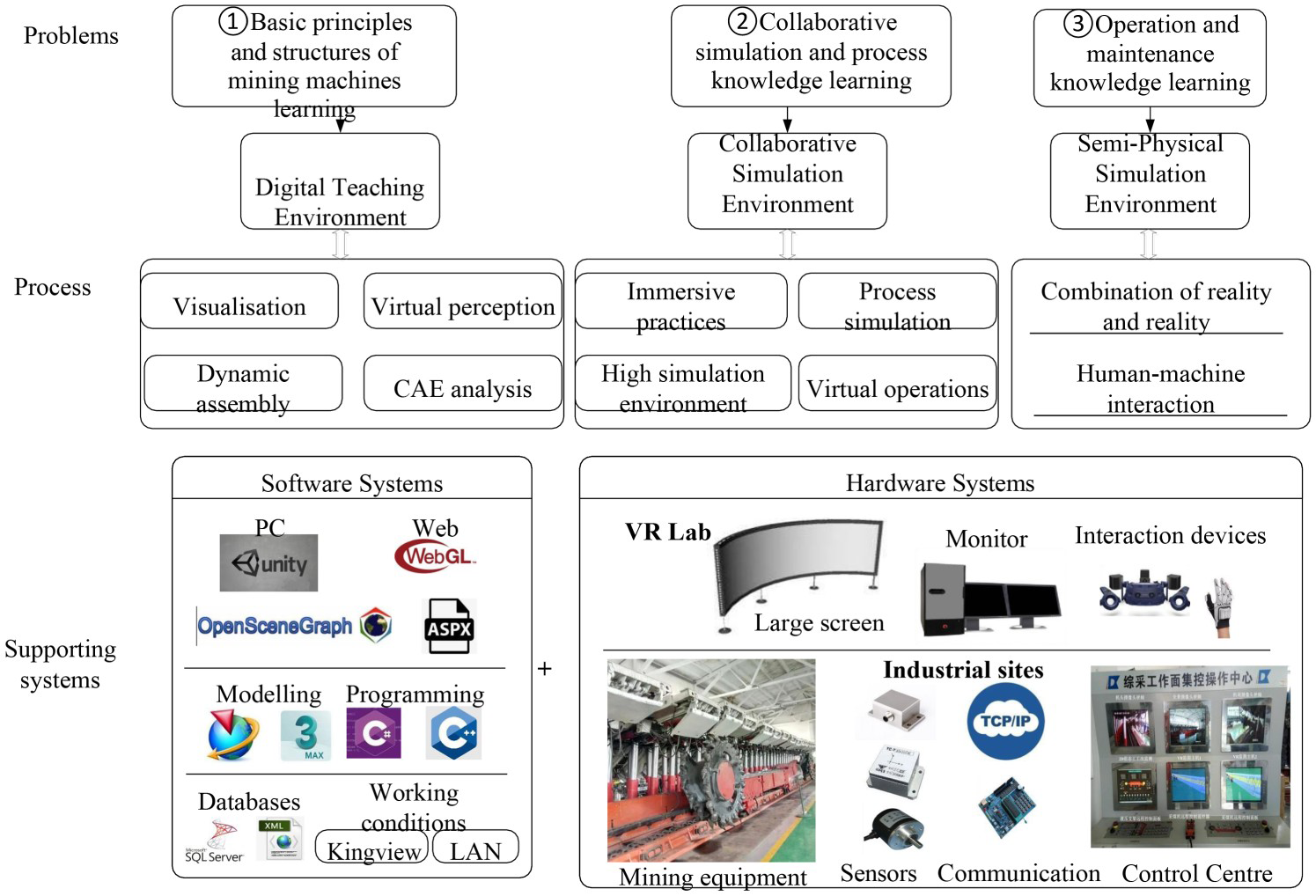
To satisfy these requirements, the test system and the related environment are created. The test system is divided into two parts: a software system and a hardware system. The hardware system is mainly responsible for providing sensory feedback and controlling the system, while the software system mainly performs various required functions, provides the interface for the hardware module and the network cooperation, and supports the subsequent expansion.
Hardware support
The hardware is mainly composed of two parts: a virtual laboratory and a test site. By constructing the basic communication system, the two parts are combined to perform relevant interaction and exchange, as shown in Figure 2.
Hardware supporting system of virtual environment.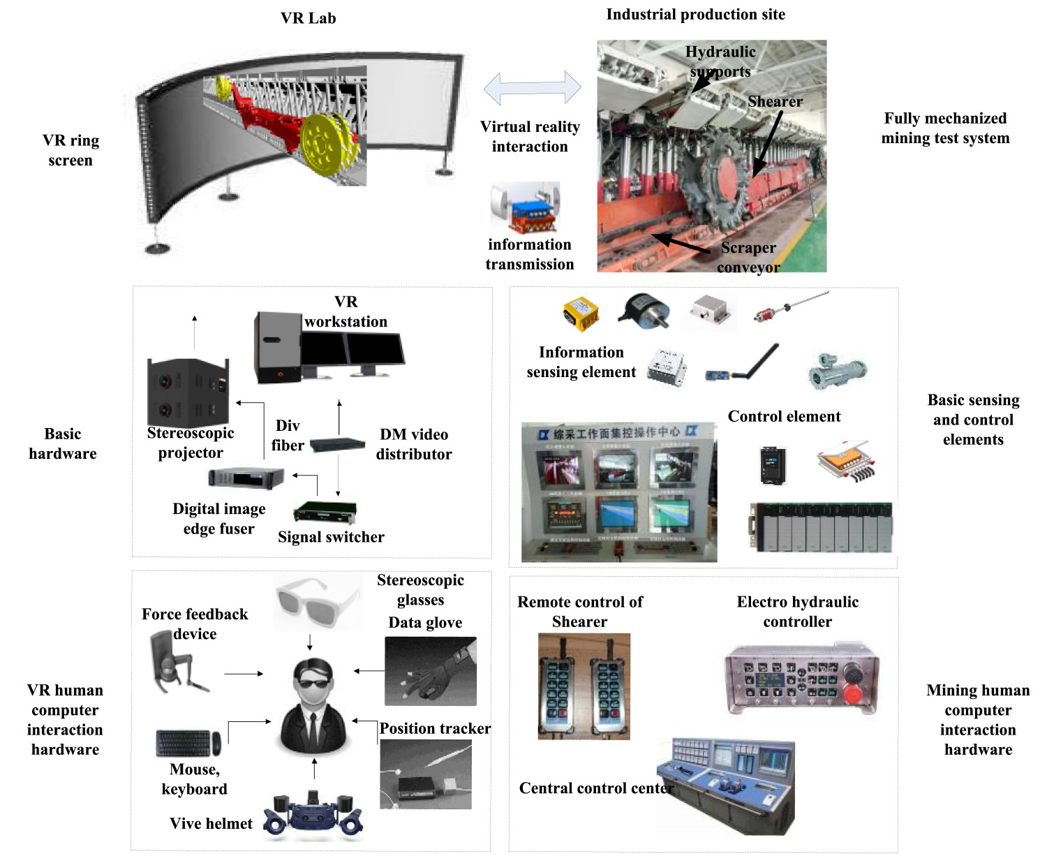
The VR part creates an integrated dual-channel pillar curtain system within the visual hardware platform, with a high level of immersion. As for the hardware itself, it is divided into basic hardware and HCI hardware. The former guarantees smooth and good system operation, while the latter achieves the interaction function between the operator and the system and enhances the perception of the operator. Data glove performs the synchronisation between the human hand and the virtual hand. The stereo glasses allow the users to have visual stereoscopic feeling. The position tracker ensures that the position in the actual environment is consistent with that on the screen. Moreover, the force feedback makes the user feel the same force as the real objects. Finally, the data helmet produces a very high-quality sound and provides users with clear pictures.
As for the industrial field part, it has a set of fully mechanised mining test systems that support the relevant automation core components and devices. By building a high-speed communication network platform, combining the wired and wireless networks, and configuring the relevant digital sensing of the equipment, the system transformation of the shearer electric control and the electro-hydraulic support control can perform real-time digital perception of the equipment, remote visual operation of the shearer, automatic follow-up action of the hydraulic support, and linkage control of the transportation.
Software support
The software is mainly created using OSG and Unity3D. Two software are connected together by 3Ds Max and connected to a computer-aided design software, such as the Unigraphics NX (UG). UG software, WebGL, ANSYS, and ASP.Net are connected to complete the expansion function in the relevant Internet environment. The software interaction structure is shown in Figure 3.
Software interaction structure.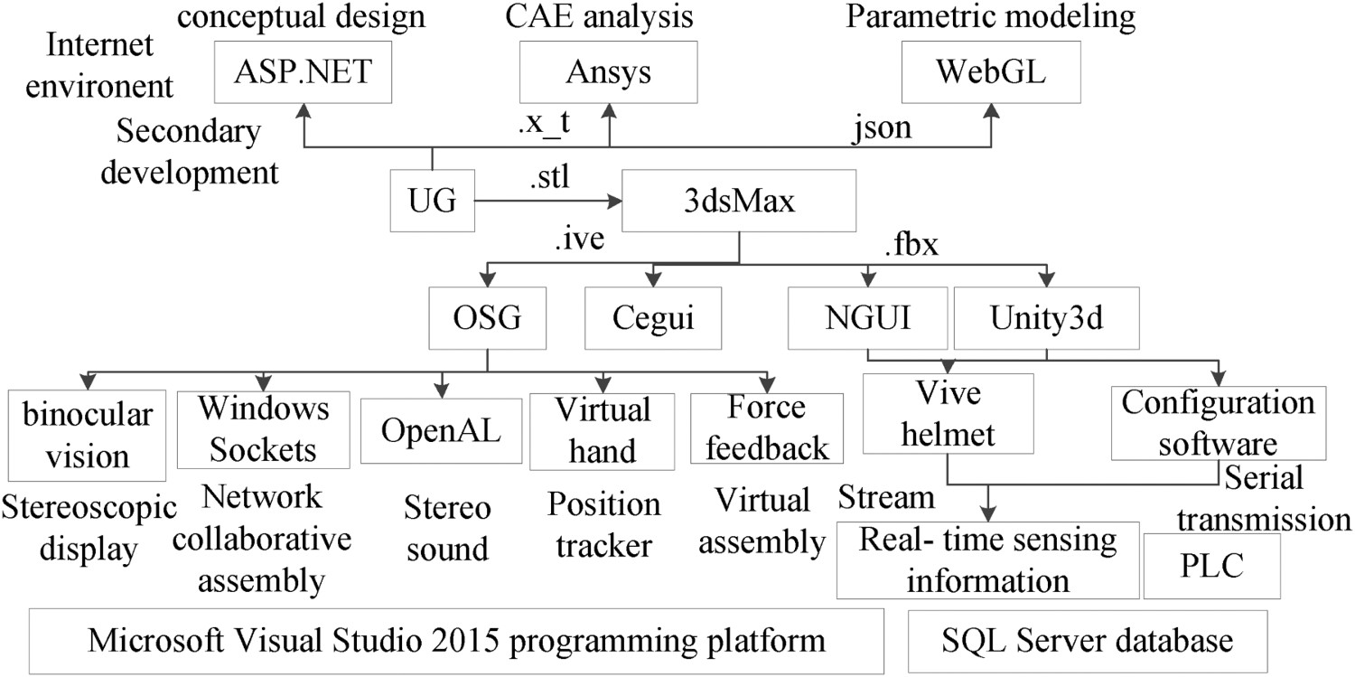
Moreover, OSG has relevant interfaces that can integrate stereo sound, force feedback, stereo display, virtual hand, and other functions. It is mainly responsible for the first stage of the digital design.
As for Unity3D, which is used to build the virtual scenes, it enables the interactions with the configuration software, database, and computing software through different software and hardware interfaces. Added to that, it drives the virtual scene and transmits the operation instructions back to the control system for real-time synchronisation; moreover, it intuitively monitors the operation status of the whole working face, and completes the second and third parts of the process.
Digital teaching and HCI method based on mining equipment
Using the design method of the immersive virtual environments combined as well as the network collaboration, a basic understanding of the structure of the mining equipment is obtained through several modules such as the virtual assembly, the HCI, network collaboration, and three-dimensional display.
Virtual assembly verification of parts
The virtual assembly test system consists of the virtual assembly and disassembly of the electrical haulage coal shearer. The block diagram of the functional system composition is shown in Figure 4.
The model selection, movement, rotation, and scaling functions allow the users to perform various operations on the assembly parts. When a model is selected, using the mouse, the Cartesian coordinate system will appear over the model. Instantaneously, the model will be highlighted and this will be achieved by changing the node matrix coordinates of the component ‘OSG:TrackballManipulator’; The path recording and the playback function record and play back the assembly path, analyse and evaluate the assembly sequence. They also initiate the OSG: AnimationPath assembly path to record a series of user's own operation process and to save it in a TXT file format. By reading the path record file and playing it back, the discrete spatial record points are demonstrated. The assembly sequence and assembly trajectory are then analysed and evaluated; The model reset function resets the model to the initial decentralised state, independently of the model state; The automatic positioning constraint function is used when the user controls the model. The system will inform the user of the distance between the current position and the correct assembly position in the x, y, and z directions, and will guide the user to conduct the correct assembly using the automatic positioning of the bouncing ball; The networks collaborative assembly function performs multi-person collaborative assembly in different places and provides the assembly results in real time; thus, each operator can state his opinions on the assembly and conduct a collaborative review; In automatic assembly and disassembly demonstration, the planned assembly path is automatically played to allow the users to understand the basic structure and the assembly planning of the coal machinery equipment. Moreover, the assembly animation of the different parts of the coal machinery equipment are automatically played when they are correctly assembled to show the user the appropriate assembly path and the best assembly scheme; The collision detection simulates the actual assembly process, avoids interference between objects, and makes the system more realistic; The stereoscopic display in various modes improves the system immersion; The hardware system supports the data glove and other assembly tools to improve the system interaction; Virtual assembly workflow of human–computer interaction.
HCI using the virtual hand
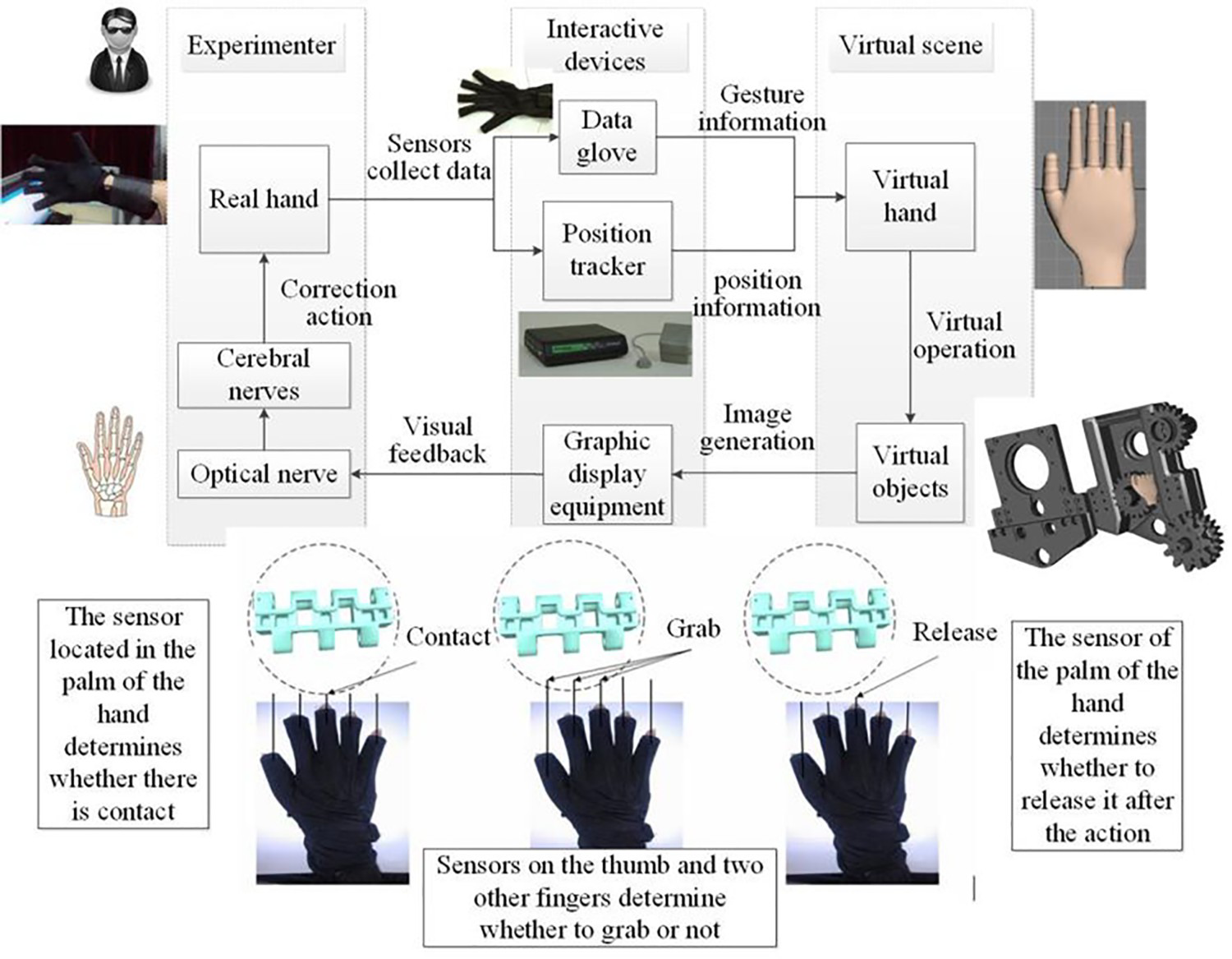
The assembly interaction of the shearer model is performed based on the 5DT Data Glove 5 Ultra and the position tracker. Data glove and other devices for interaction are used to establish a one-to-one mapping relationship between the human hand movement and the virtual hand movement. In particular, the data glove is used to obtain the angle information of the human finger joints, and the position tracker is used to obtain position information of the human hand in the 3D space. This information is then transmitted to the computer where state of the virtual hand is changed in real time accordingly, and feedback is provided to the personnel using the graph display equipment, as shown in Figure 4.
Network collaborative assembly
The network collaboration has become crucial in the virtual experiment. It supports the multi-user real-time collaborative communication analysis, increases the actual effect of the virtual experiment, and sends and receives tokens to conduct multi-user experimental training, which is convenient for the user's actual interaction training.
In the collaborative experiment, the user moves the component in the client, and the network communication module sends the specific information of that component (e.g. OSG world position matrix and physical world position matrix) to the server, which then broadcasts the information to other clients. After receiving the message, other clients analyse the message, feature the corresponding data segment, find the component in the scene and the new call-back function, and update the component location information. The specific workflow is shown in Figure 5.
Workflow of network collaboration.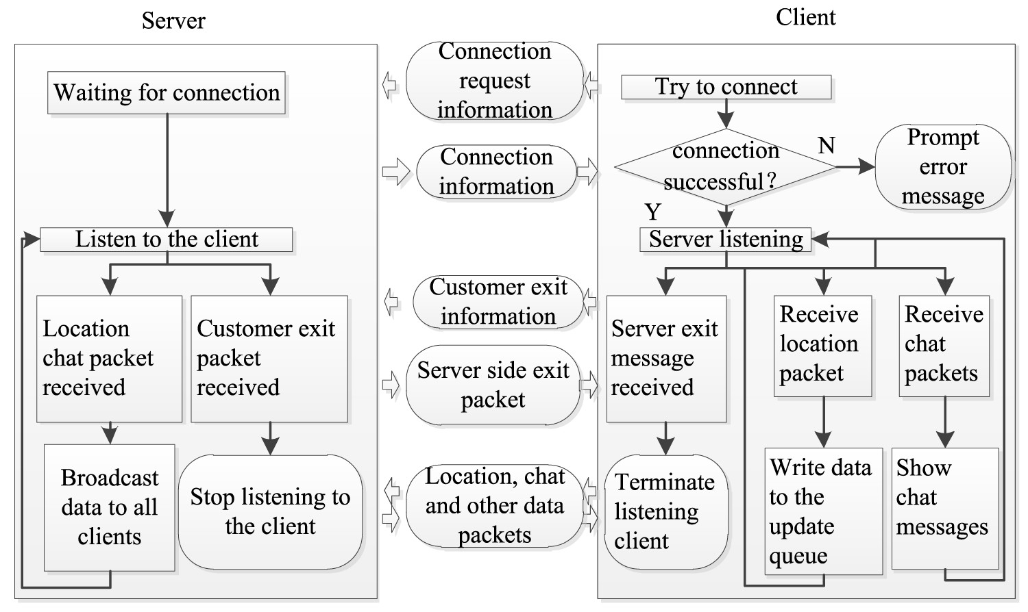
Stereoscopic display
Stereoscopic display is among the key technologies of VR. It aims to making users feel the depth and the level of the scene, as well as the actual distribution of objects. The passive stereoscopic, displaying of the experimental system, is performed based on the binocular parallax technology. Moreover, hardware devices, such as polarised eyes, are required for the interactive observation. In particular, the projector is used to generate beams having mutually perpendicular polarisation directions in order to project the image on the large screen. Polarised eyes (referred as polarisers) with orthogonal light transmission directions are used for observation to induce binocular parallax and to generate immersion. This principle is illustrated in Figure 6.
Schematic diagram of passive stereoscopic display.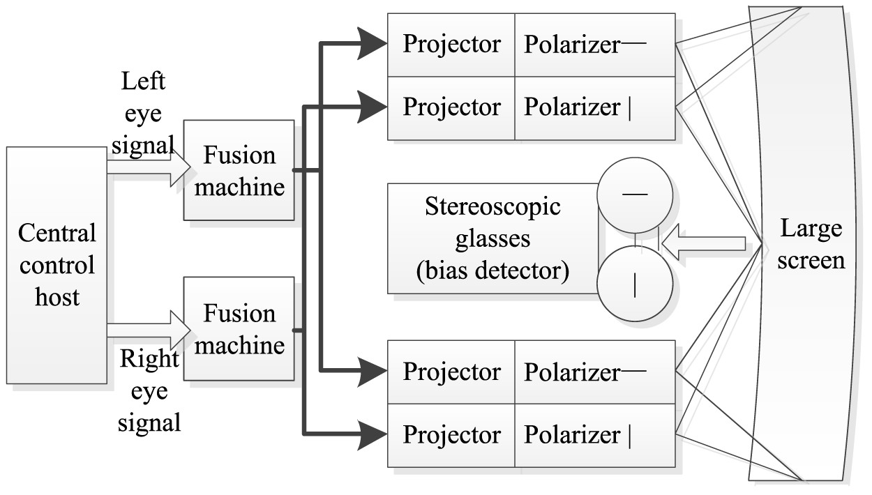
After studying the principle of stereoscopic display, it is important to analyse the effect of the stereoscopic display on the virtual assembly test system of the shearer. For this purpose, OSG encapsulates the settings related to the stereoscopic display in the OSG: display settings class. The stereoscopic display switch can be set using the SetStereo (bool on) function, and the stereoscopic display effect can be adjusted. The class is shown in Figure 7.
Stereoscopic display class and system setting interface.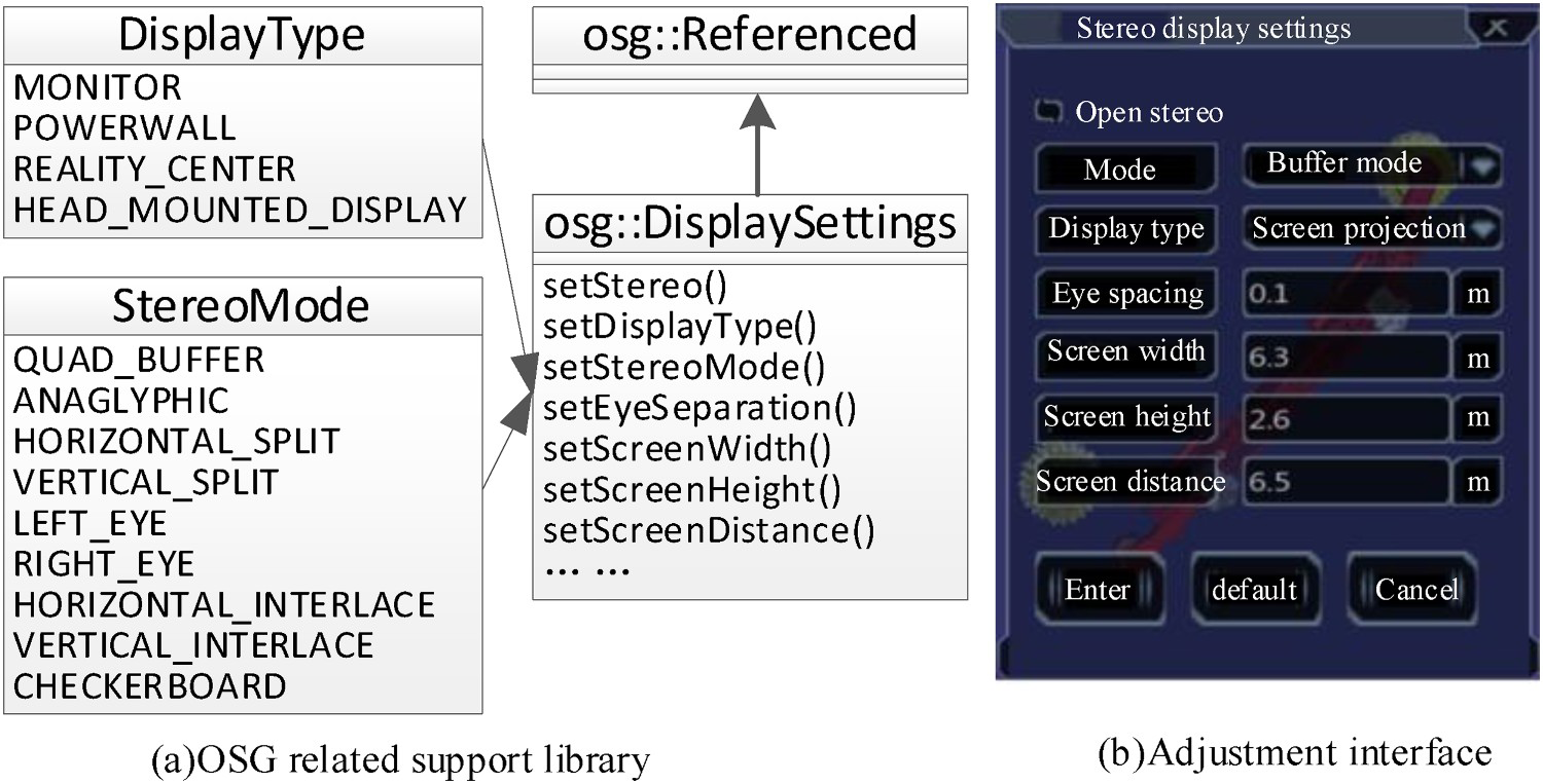
Collaborative virtual simulation and HCI for the mining equipment
After completing the equipment design, it is imported to the Unity3D software, and all the objects of the fully mechanised mining face are placed in the 3D VR world with a high degree of restoration to conduct the simulation and data visualisation. The virtual simulation of the single machine and the coordinated simulation of the three machines, should then be performed. The simulation of the whole system is conducted based on the real data integration of the man–machine environment and other multi-factor conditions, and the relevant interaction is performed using the 2.0 HTC Vive helmet.
Equipment simulation
The design of each equipment in the virtual scene should be performed and the related action of the hydraulic support should be achieved using the C# script design. (1) the initial state, (2) the plate is retracted, (3) the front probe beam is contracted, (4) the column is lowered, (5) the overall equipment moves forward, (6) the column is raised, (7) the front probe beams, (8) the plate is extended, (9) the scraper conveyor moves. The movement diagram of the hydraulic support is established (refer to Figure 8), and the relevant control interface is reserved.
Movement states of hydraulic support.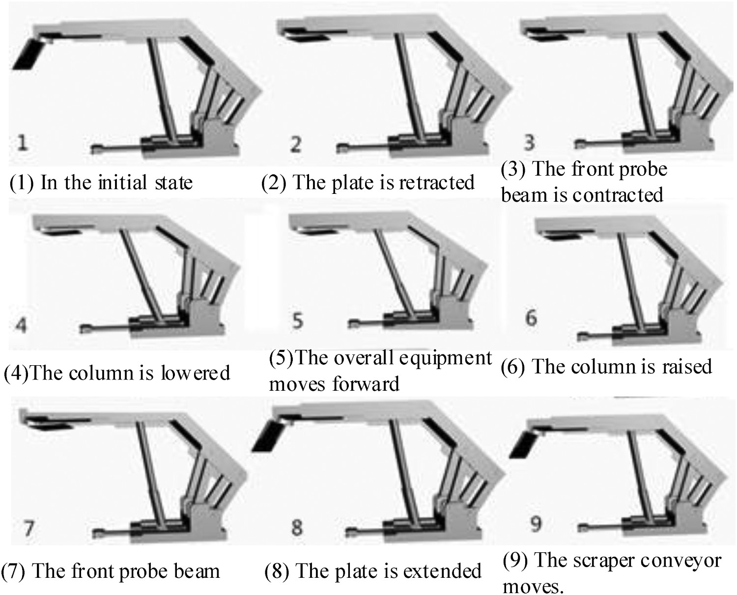
Man–machine environment integrated design
To create a virtual mine operation scene, it is also important to integrate the underground environment and the core of HCI in addition to the equipment. Thus, the enhancement of the immersive experience and the performance of the coordinated operation of man–machine environment will be checked, as shown in Figure 9.
Virtual simulation environment which integrated man, machine, and environment.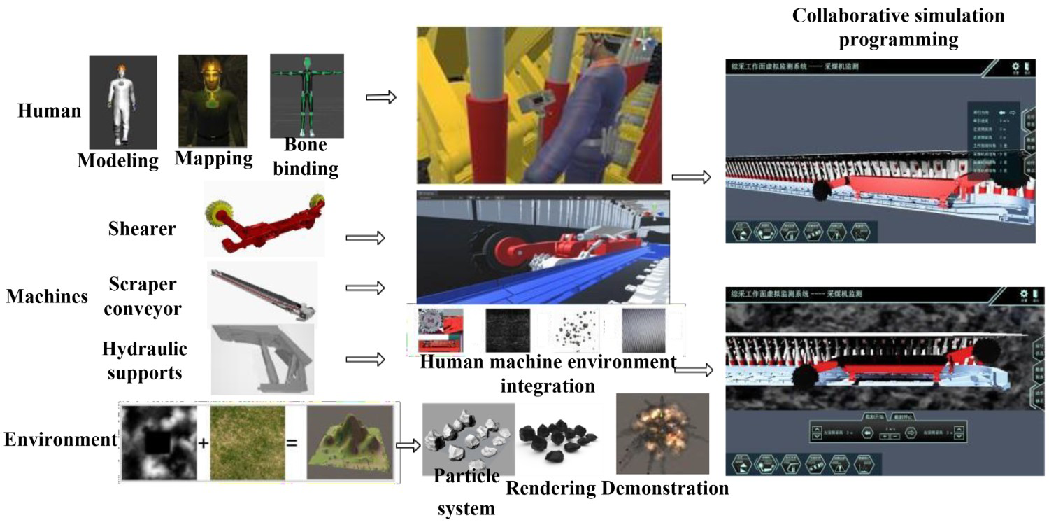
Through the system, the users can see the simulated alarm prompt and the function introduction of the equipment. He can also roam the fully mechanised working face to check the equipment operation, and fully understand the real situation of the equipment and the environment in the whole working environment. This feature will allow the user to achieve a clear monitoring, an efficient learning, and a real-time analysis, so that the designers can immediately identify the main problems in the equipment during their usage, their maintenance, and their monitoring. The whole process is summarised as follows:
The establishment of the panoramic modelling platform: different modelling software are first used to complete the miners, the coal mining equipment, the mine terrain, the simulation roadway, and other parts. Then the complete layout of the underground equipment is delivered. Afterwards, the rules of the conventional roadway layout are followed and the conventional equipment, such as the miner's lamp and the water pipe, are added to comprehensively present the visual simulation model of the underground fully mechanised mining work; The simulation particle effects of roof fall accident, water leakage accident, gas, and coal dust explosion accident are provided using the particle rendering system of Unity3D. In addition, the underground equipment fault prompt effect is created using Photoshop. Moreover, the underground environment rendering is performed, and the sound effect is implemented to make the system more realistic. Virtual operation and maintenance of mining equipment: the coal machine model production is conducted in UG, a three-dimensional model of the equipment is created, a realistic texture rendering is performed, a parent–child relationship and a motion relationship are established, and, finally, the movement operation is completed under the working state of coal mining. Furthermore, the Next-Gen UI kit (NGUI) system is used to establish the equipment. Where the button is first clicked, and when the event is triggered, a voice that introduces the specific situation of the coal machinery equipment can be heard. Equipment operation demonstration: based on the developed 3D model, the event system of Unity3D is applied to program and edit NGUI in order to perform the simple simulation teaching operation of shearer and hydraulic support. Miners roaming: using the third-person or first-person roaming systems, the users can freely roam in all the areas of the fully mechanised mining face. It can also switch anytime the observation state. This leads to further understanding of the fully mechanised mining face. Accident demonstration: the use of the special particle and sound effects, combined with the UI production, as well as other functions, can enhance the authenticity of the whole environment, imitate the real scene of mine accidents, and deepen the impression of the accident. Fault demonstration: the underground equipment will be displayed through the cooperation of the particle system and User Interface (UI) production. If a fault is detected, the alarm will appear on the screen to guide the underground maintenance personnel to quickly find and reach the designated position and solve the problem.
Cooperative simulation operation method
Using the script programming in Unity3D, the cooperation of the three machines in the fully mechanised coal mining face can be summarised as follows:
The front roller of the shearer is forward 2–3 hydraulic supports, and the implementation of actions 2 and 3 starts; The front drum of the shearer is backward 2–3 hydraulic supports, and actions 4, 5, and 6 start; After the shearer, the roller is backward 2–3 hydraulic supports, and actions 7 and 8 start; After the shearer, the roller is backward 4 hydraulic supports, and action 9 starts;
Virtual roaming and process design
The system will automatically generate an Eventsystem in the Unity3D editor, which corresponds to a canvas object. The two systems are generated using the NGUI. This function is also attached to these two functions when editing and operating the demo system.
The EventSystem function is responsible for managing the project, whereas the BaseInputModule function handles the hardware input, and the BaseRaycaster is responsible for determining the target object. In order to better analyse the action of the hydraulic support, the overall structure of the hydraulic support is simplified to enable a linear simulation. Moreover, its motion mode and the maximum range of the motion are set and constrained. A non-human joint is placed on the hydraulic support to achieve the setting of moving skeleton and the range of motion. This system creates two kinds of control demonstration system: the shearer control interface and the hydraulic support control interface.
The HTC Vive VR equipment is mainly composed of a helmet, two interactive handles, and two locators. This equipment can be used to develop a panoramic VR roaming system for a fully mechanised coal mining, as shown in Figure 10. As for the HMD of the HTC Vive, it is connected to the computer. The roaming scene of the fully mechanised mining face can be performed after wearing the helmet device, referring to the existing three machine matching models and the roaming scene in Unity3D. The coordinated operation of the three machines can be observed from all aspects and angles.
Virtual operation using HTC vive helmet.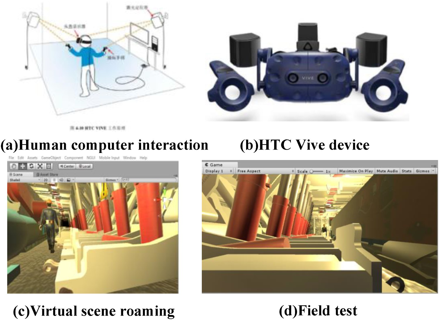
VR mapping and HCI of the mining equipment
After completing the equipment design and this simulation phase, VR interaction operation and maintenance are conducted. The problems to be solved are summarised as follows: the real-time mapping channel design from the real-time sensing information to the virtual environment, the channel design from the virtual environment to the actual environment, the collaborative operation and human operation button drive, the HCI hardware interaction mode, the manual remote inspection, intervention, and application. The overall framework is shown in Figure 11.
Overall design of virtual–real interaction.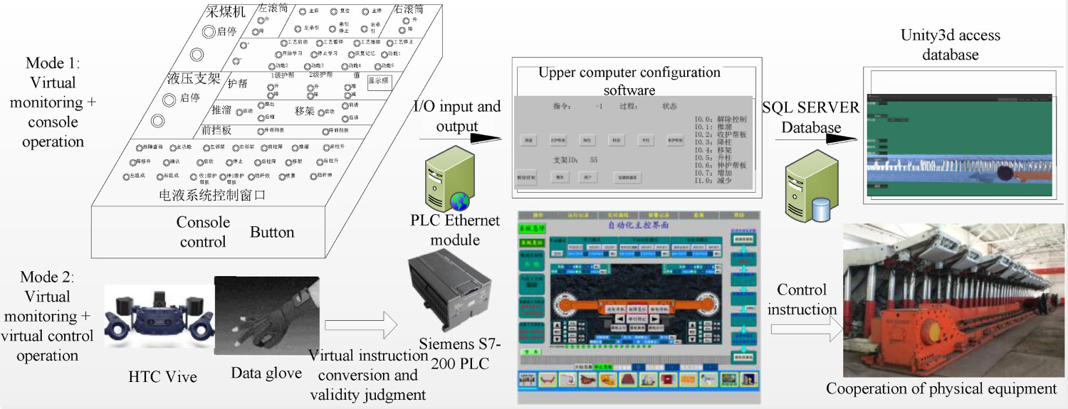
Design of the VR interaction channel
In the real to virtual aspect, the virtual monitoring task should be first achieved. The virtual operation picture in the virtual laboratory should correspond to the real-time test platform running picture. The KingView monitoring host in the central control room that stores online data of the sensor elements in real time using the SQLServer database. Unity3D can access and read in real time the online information of all the sensors through the database and the C# interface. Therefore, the real-time reading of the latest data is then assigned to the relevant variable interface of the corresponding virtual equipment. This is done to do the online actual driving of each virtual piece of equipment and the virtual scene of the completely mechanised working face. The signal of the strapdown inertial navigation device, installed on the shearer, is connected to the virtual software as shown in Figure 12.
Real-virtual channel.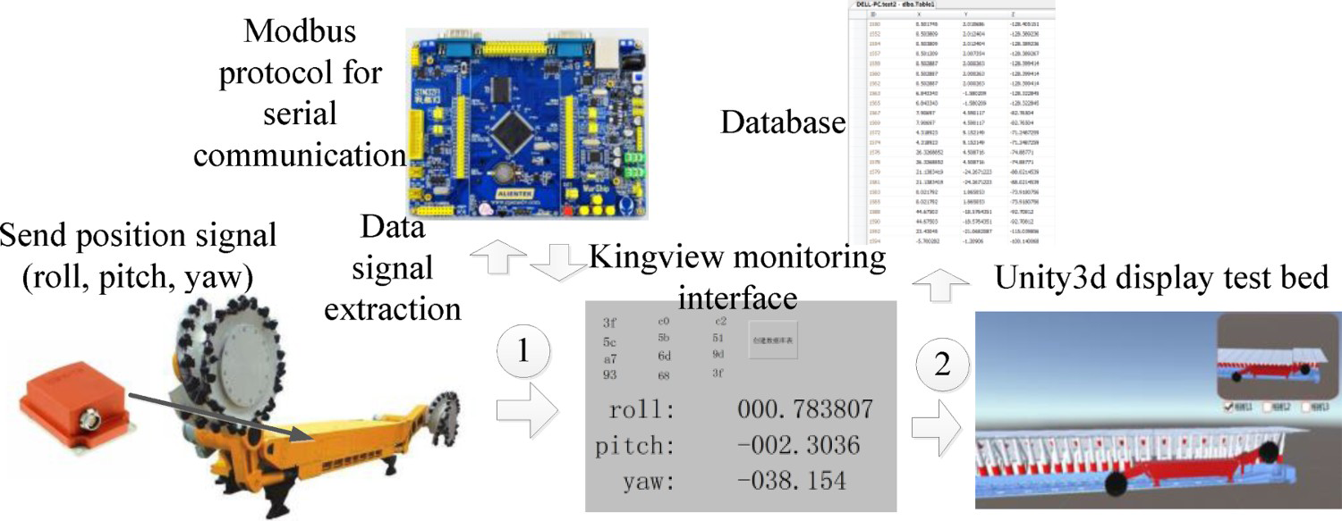
The process of transforming the operator's VHCI into the PLC control command in the central control room, is summarised as follows: the interactive operation instruction in Unity3D, corresponding to the virtual variables reserved in the virtual software, is determined. The virtual variables are transferred to the table corresponding to the equipment through the interface written in C#. Afterwards, the SQLServer software BC interface is transmitted to KingView that is connected to the PLC of the central control room through the OPC interface, and it transmits the required data to the PLC control system of the corresponding physical equipment through the RJ45 remote wireless transmission network. This enables the equipment operation.
Interactive mode of virtual monitoring and manual console intervention
The VHCI interface is a virtual operation tool created using the NGUI module in the Unity3D environment. It includes a remote operation panel of the shearer, a remote operation panel of the hydraulic support, and a remote controller of the virtual shearer.
This paper mainly uses a PLC relay to control the button previously set on KingView, and the industrial Modbus protocol to allow the Siemens S7-200 controller to control KingView. The corresponding I/O signal of the PLC is matched with the I/O discrete value established in the KingView library, and the established discrete variable is animated using the text display control developed in KingView connect that performs a real-time control of the PLC output state.
To perform the communication between the PLC controller and KingView, it is important to provide the PLC controller program control code, mainly through the corresponding control of normally open control inputs and relay coil output.
The code of the KingView program is developed to ensure that this software collects the PLC signals (hydraulic support number ID and operation instructions) and saves them in the SQL Server database. Thus, an empty object is created on the Unity3D platform. The C# language is used to read the data from the database table attached to the empty object, and the real-time data are read by Unity3D. The C# script is written to control the digital model of the hydraulic support, so that real-time dynamic control of the hydraulic support can be performed.
The main block diagram of the hydraulic support is used. The GameObject. Find () function is used to match the data information in the database read by Unity3D, where number denotes the read hydraulic support number and demonstrates that the virtual hydraulic support is in performing actions mode, the state value denotes the instruction code, and the different values demonstrate that the current hydraulic support is performing different actions. Finally, through object-oriented programming, the control of the hydraulic support is performed, while its speed is controlled in real time according to the shearer speed.
Virtual remote inspection and monitoring method
The virtual interface display and the splitting module of the position judgement information show the virtual monitoring interface and VHCI interface on the simulation projection curved screen. This allows the operator to manipulate the virtual button and to control remotely the virtual monitoring interface. Moreover, the virtual interface performs a virtual operation through the block display and the virtual monitoring technologies. The screen is divided into multi-scene pictures that are displayed, section by section, on the simulation projection curved screen. This may solve the problem of the fully mechanised mining scene being too large to be displayed on a virtual screen. Moreover, it allows to perform a rapid positioning and switching of the operators in the virtual scene.
The method for determining whether the virtual operation is effective consists of judging first the split space of the fully mechanised coal mining, and then responding in real time to the VHCI interface of the corresponding equipment. The next step consists of determining the operator's position and its orientation in real time, and then judging other people's body posture and the operator's hand and virtual face using the information of the operator's body, limbs, palm, and finger movements is then generated. If the contact and the response conditions are met, the operation will be triggered to find the corresponding operation equipment. After each select, it is important to select the command permission button in order to avoid accidental touch (Figure 13).
Virtual remote inspection and monitoring method.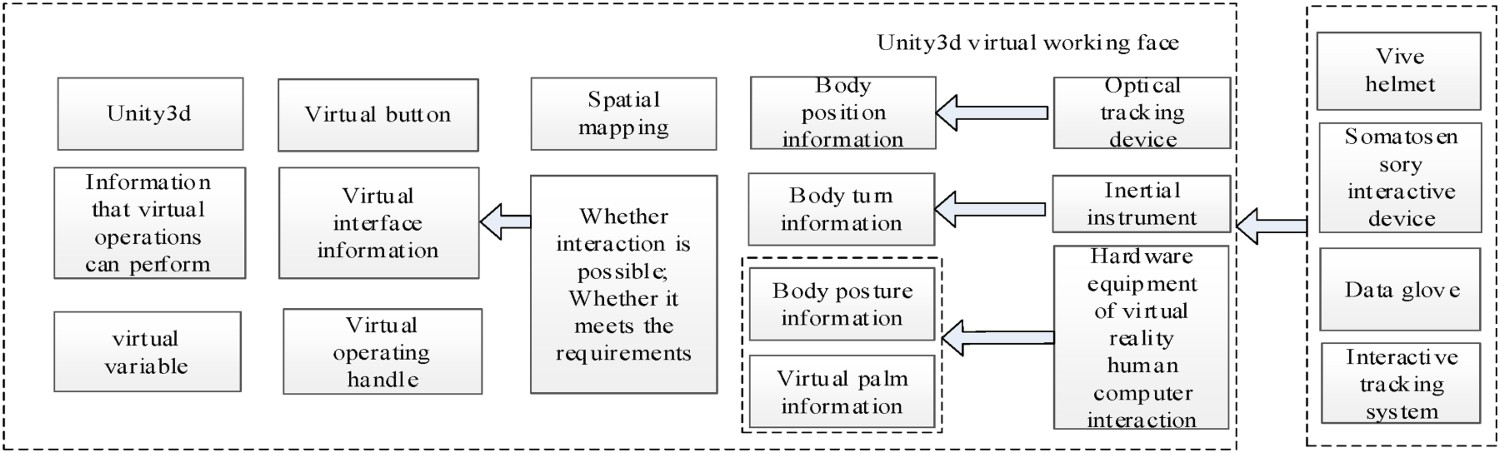
Case study
Digital design and HCI test of mining equipment
After completing the relevant digital design, the shearer type is selected. Moreover, after the detailed structural design is completed, a parametric model of the whole machine is created based on WebGL, then a virtual assembly is performed based on the model, and finally, the virtual subsystem is entered. Afterwards, the relevant buttons of the UGUI are controlled by clicking the following set of instructions: ‘select model’ → ‘traction unit’ → ‘transmission gear’ to enter the transmission operation interface of the traction system. This operating system includes features such as ‘record path,’ ‘operation model,’ ‘close record,’ and ‘playback path.’ The menu selection and scene screenshot are shown in Figure 14 where at the right, the assembly path planning at each part is presented.
Verification of main function of virtual assembly.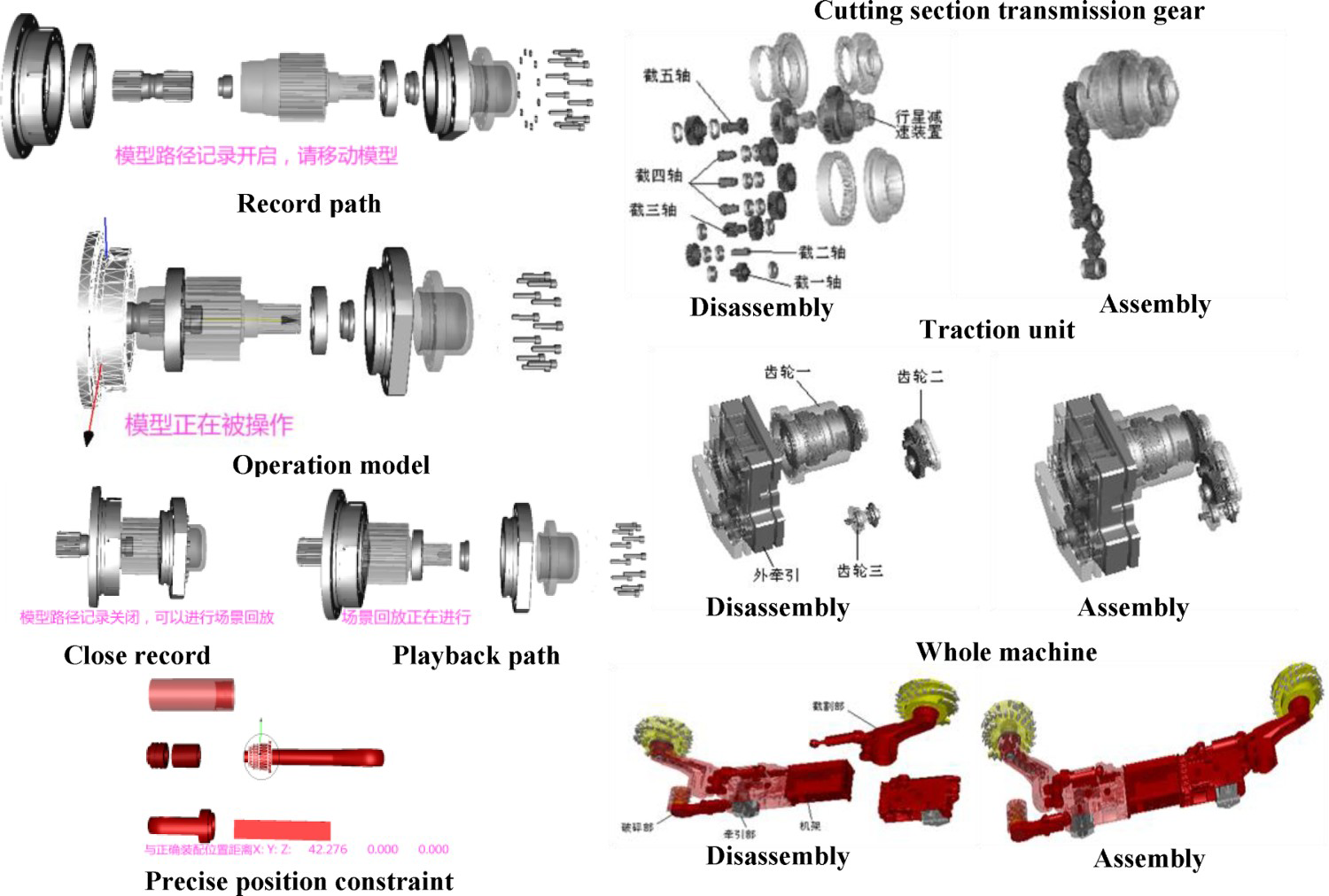
The network cooperation module is responsible for the remote real-time disassembly and assembly of all the shearer components. The server monitoring program is run on the server side. The network collaborative control window appears at the server side, allowing thus the client to connect with the client IP. The shearer components can then be cooperatively assembled. The effect of collaborative assembly is illustrated in Figure 15, where the left-side subfigure presents the active operation and the right-side subfigure shows the client of the collaborative assembly.
Experiments of network collaborative assembly.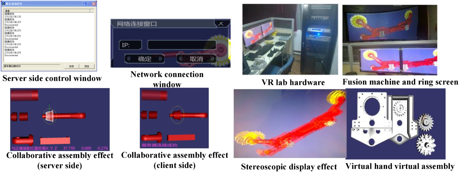
The effect of the system in the laboratory is also presented at the right side of Figure 15. It can be seen that the model display is fuzzy. in more detail, when the experimenters wear polarised glasses, filter, and fuse, they can enjoy the immersive stereo display effect. Moreover, the virtual hand is connected to the position tracker data line and the host, the data glove is worn on the right hand, the position tracker sensor segment is inserted into the data glove, and the stereo glasses are worn to complete the grasp and for assembly.
The test and the analysis of each functional module of the shearer virtual assembly are conducted in the virtual design laboratory. After the testing, the functions provided by the virtual assembly experimental system of the shearer can be reasonably used in the virtual assembly of the shearer. This demonstrates that the relevant method of the virtual assembly is accurate, and it can effectively evaluate the assembly of the products.
Collaborative virtual simulation and HCI test of mining equipment
In the second stage, the digital equipment model created in the first stage is imported into Unity3D (Figure 16). A virtual simulation is conducted by inputting the different planning conditions according to the scheme design using several mining key parameter models embedded in the bottom layer where the is data recorded in real-time operation. The different cutting environments of the shearer, the way the miners operate the equipment, and the adaptability of the designed equipment in the case of underground fire, are then simulated. By comparing the virtual simulation results of the different schemes, the performance parameters and process parameters are optimised in the post-processing module, and the operation is performed according to the optimisation results.
Experiment of virtual simulation phase.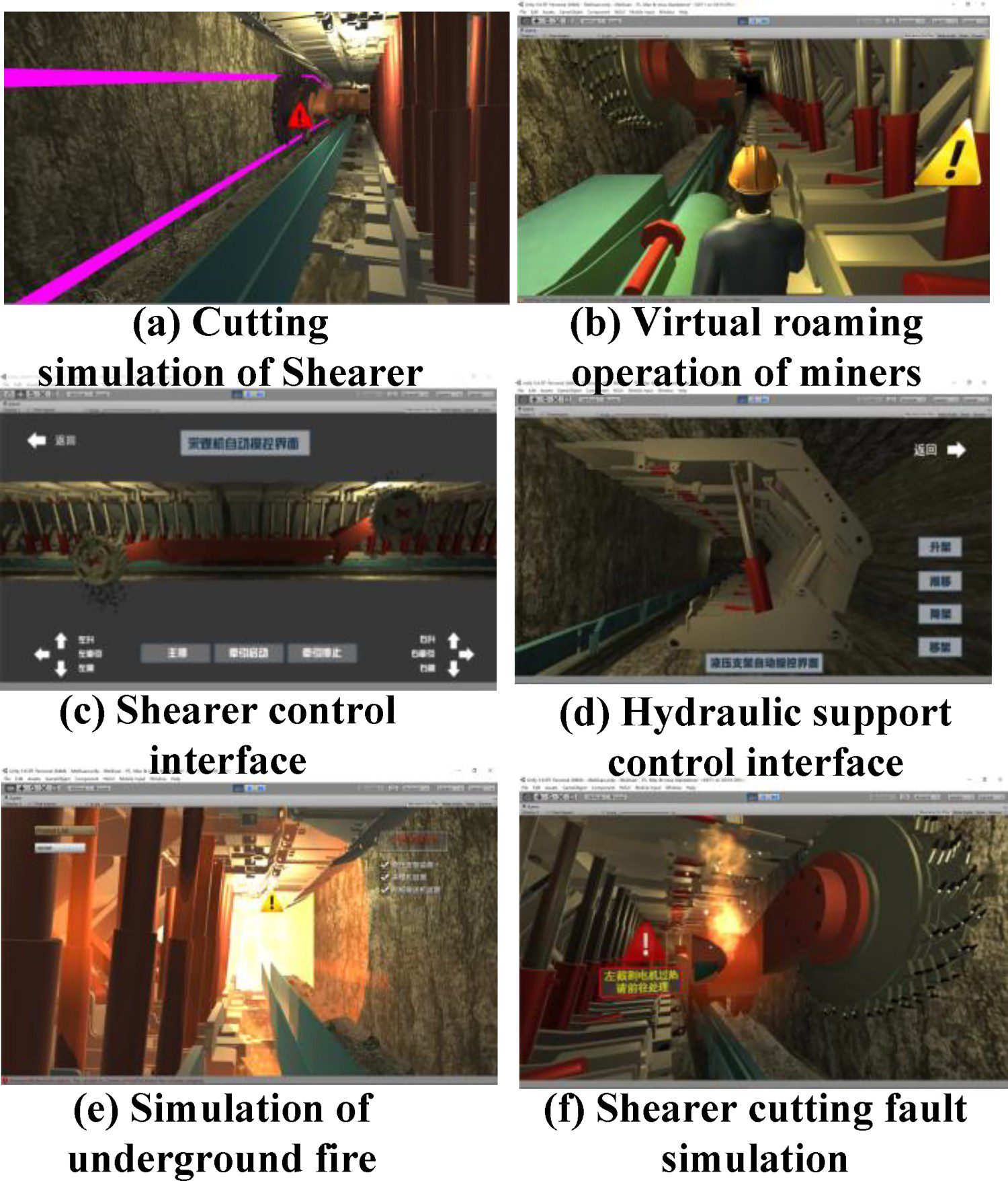
VR mapping and HCI test of mining equipment
A relevant virtual monitoring system is also developed. In the interface design, the upper-left area presents the operation status monitoring panel of each equipment (Figure 17). The running position of the shearer, displayed by data monitoring is consistent with that displayed on the VR monitoring interface monitoring panel. The hydraulic support group also exhibits the same state as the actual scene.
Experiments of virtual-real mapping.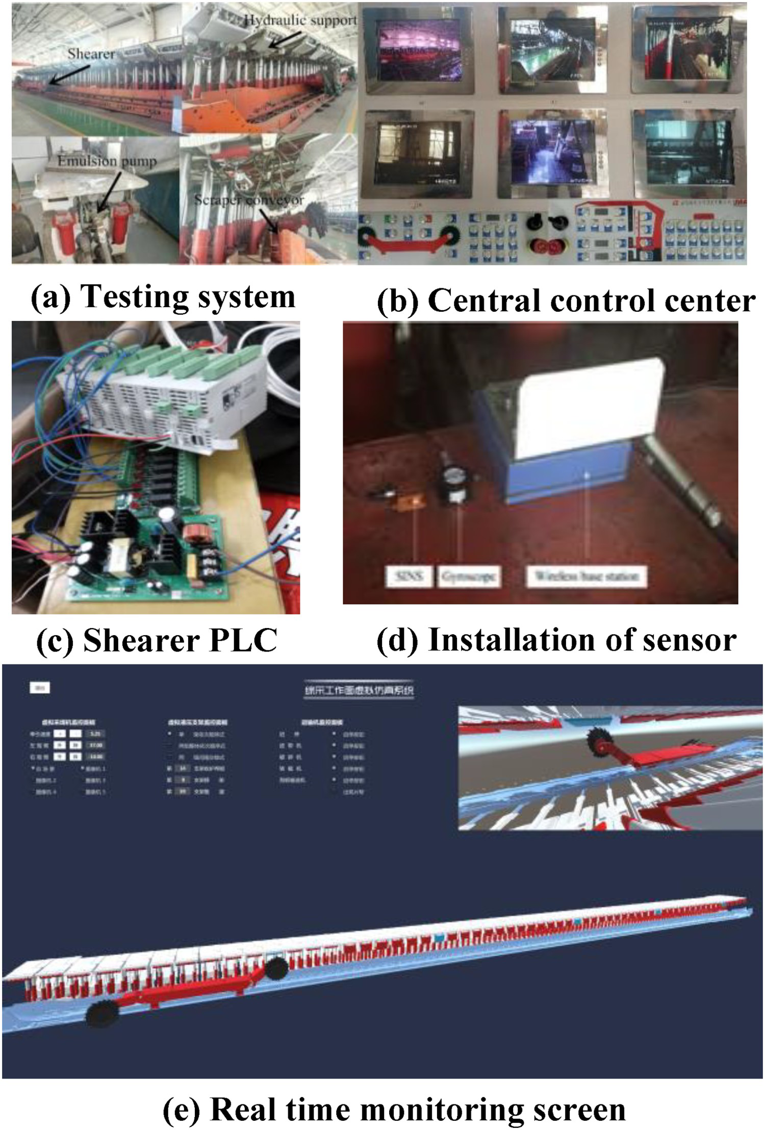
The mode I test is based on the omnidirectional stereo monitoring mode and system where a remote visual coal mining and a VR monitoring test are conducted in the central control room and remote-control room of the gateway, as shown in Figure 18. The PLC control elements are installed in the shearer control box to supply power to the high-voltage circuit and control circuit. After establishing the communication between the upper computer and the field equipment, the upper computer can control the field equipment. The up and down directions of the two shearer cutting drums can be controlled through the green arrow buttons of left up, left down, right up, and right down of the upper computer. The test indicates that the operation response time of the remote controller is less than 800 ms. The shearer alarm trigger emergency stop time is less than 500 ms, which assures the remote-control accuracy.
Experiments of two modes of virtual operation.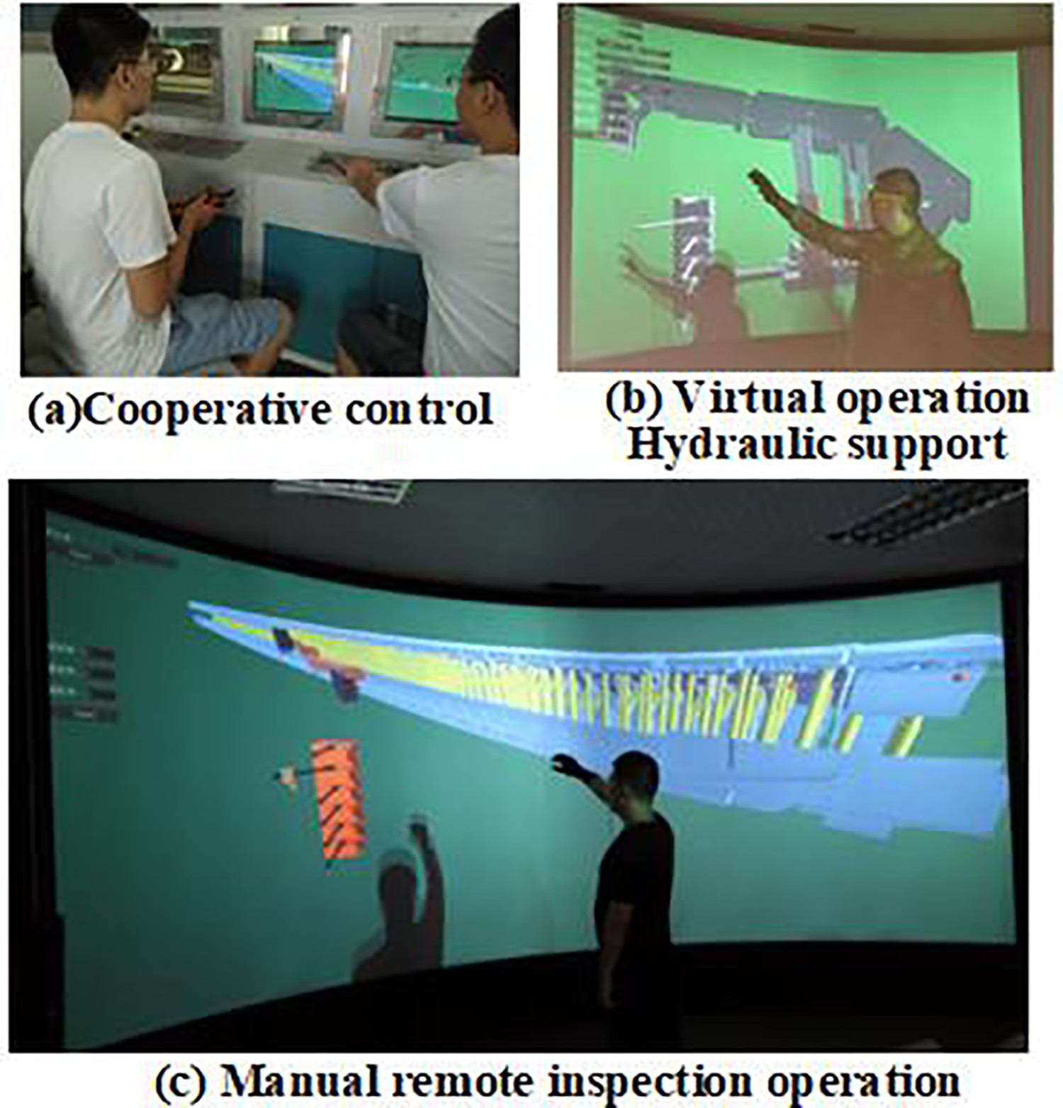
In mode II of the VR laboratory, the operator holds the operating handle or the virtual hand and the position tracker, in order to enter the virtual monitoring screen of the fully mechanised working face equipment, in a real-time operation in the virtual software of the simulation projection circular screen display. It also interacts with the buttons and the virtual operation panel in the virtual HCI interface. An optical tracking device and an inertial instrument are then used to acquire the information relative to the position and the direction of the human body in the virtual environment. Information on the human body posture and virtual palm are acquired using the VHCI hardware equipment. The information on human posture and VHCI interface can be used to judge the quality of input and to complete the interaction.
When the operator finds that the hydraulic support in the working face is in an abnormal position, the virtual interface display and splitting modules are initialised to quickly lock and locate the virtual screen where the hydraulic support can be found; thus, the corresponding virtual operation interfaces are called out. These operations include a manual operation valve of virtual hydraulic support, a virtual electro-hydraulic controller, and a virtual support remote controller for interaction. Afterwards, the operation instructions are passed through the virtual interface. The man–machine environment is then transformed to the PLC control command in the central control room, and the command is transmitted to the hydraulic support in order to complete the operation. The obtained results indicate that the response time of Vive handle and the virtual hand action takes less than 1000 ms. In addition, the shearer alarm trigger emergency stop time requires less than 800 ms, which basically achieves the control accuracy.
Overall test
Based on the 99 students’ comprehensive ability in the early stage, the students in a class are divided into three groups of 33 students each. The first group adopts traditional textbook teaching, whereas the second group only uses VR teaching (i.e. the first and second subsystems of the virtual teaching environment), and the third one conducts interactive environment teaching and added the third VR mapping based on the second group for three months.
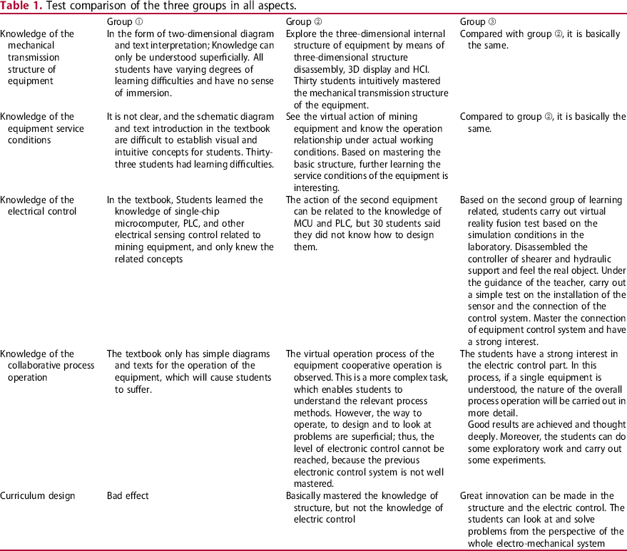
By examining the mechanical transmission structure of the equipment, its service conditions, its electrical control knowledge, and its coordinated process operation, as well as the course design after learning, the feedback of the three groups is summarised as Table 1:
Compared to the traditional teaching methods, this immersive virtual system is used for training and teaching, that is, learning the knowledge of equipment structure design and the information about the conditions of use. The second group uses the first and the second subsystems of the virtual environment. It has clear advantages compared to the third group which uses the first, the second, and the third subsystems of the virtual environment. It is mainly reflected in the highly immersive operation and processing of the internal structure, and the deeper understanding of the internal transmission structure of each piece of the equipment. It includes motor transmission, spur gear transmission, bearing, planetary transmission, gear shaft, and other related concepts, that are easy for students to interact with, and hence practice the knowledge learned in the basic courses and specialised textbook. The third group has more training related to the virtual real mapping operation than the second group. However, the change in structure and the knowledge use are not obvious, which indicates that a simple virtual assembly and simulation of the equipment have a good effect on the learning structure and use conditions; For the equipment electrical control and the collaborative process operation knowledge, the second group observes the basic knowledge under actual underground conditions, which allows the students to acquire more knowledge. However, as students are inexperienced and have no exposure of the real-world equipment, there is no clear improvement in the practical knowledge of the PLC and single-chip microcomputers. The third group can see the equipment of the PLC, single-chip microcomputers, and sensors through the relationship between the virtual program and the test system and start to operate and connect with the virtual program. After hands-on operation practice, they achieved satisfactory results, they can deeply think about problems, do some exploratory work, carry out some tests, and operate machines. These findings show that in terms of electronic control and overall system design, the use of systems with virtual and real mapping interaction can improve the students’ engineering practice capacity. Curriculum design is a comprehensive practice method of designing a certain mining equipment after learning professional courses. The first group has poor curriculum design results due to the lack of solid knowledge learning. As for the second group has enhanced the ability to think about problems in structural design, usage, and maintenance, but its electronic control is still poor. Finally, the third group exceeds, in structural design or electric control, and it has strong ability to solve problems from a systematic perspective, with more design results and stronger training ability. Test comparison of the three groups in all aspects.
Conclusion
VR can be well integrated in teaching mining. Through the virtual assembly simulation and virtual scene interaction, abstract experimental processes can be vividly demonstrated in a realistic and 3D view. The system maximises the advantages of virtual component resources and improves the teaching effect. In this study, the traditional virtual experiment without data interaction was upgraded to the VR interaction experiment. It is combined with the mining production test system of the laboratory for transformation and upgrading, so that students can carry out interactive exploratory experiments while simulating the underground industrial field under the conditions of the laboratory. This greatly improved the students’ ability to comprehensively consider the structure, electric control, and design from the perspective of systems. This system integrates a series of VHCI hardware, allowing the students to complete the product design in the virtual environment, immediately test the operating conditions and status in the actual underground production, and complete the actual operation and maintenance.
All these tasks provide a direct and visual sense of the scene and a novel model for the design and development of new products. As for the future work, we aim at improving the presented work, so that more enterprises promote the application.
Footnotes
Disclosure statement
No potential conflict of interest was reported by the author(s).