
Abstract
Abstract
The emergence of additive manufacturing (AM) technologies (also known as 3D printing) promotes the reduction of material consumption in terms of avoiding the repeated fabrication of dies as well as comparatively high material efficiency. However, despite widespread application and evident advantages over traditional manufacturing techniques, AM still suffers from redundant support material usage when printing parts with overhanging features. In this article, a support generation method through print path planning is proposed for the first time, with the aim of reducing support material consumption in AM of parts with flat features. Print path can significantly influence the support usage when considering the longest printable bridge length. Two parts are printed by our new method with much less support consumption than general line and grid support generation methods. The results show the effectiveness of this new support generation method in terms of both reducing the support consumption and finish surface deterioration, enabling AM to be a more environmental friendly and sustainable manufacturing technique.
Introduction
Additive manufacturing (AM) is defined by the joint ISO/ASTM terminology standard to be the “process of joining materials to make parts from 3D model data, usually layer upon layer, as opposed to subtractive manufacturing and formative manufacturing methodologies.” 1 The technologies represented by AM are the 3D analogue to ubiquitous 2D printers. This similarity of AM to 2D printing has given rise to the alternate common name of 3D printing. Three-dimensional printing technologies have been rapidly developed and widely applied in the fields of aerospace, engineering, medical applications, and marine. The salient part of the definition is use of a computer to translate a solid model into a real part. The manufacturing process starts from the bottom of a product and continues successively layer by layer to the top. This leads to problems for overhangs that cannot be printed as there is no supporting layer beneath them.2,3 Support structures have to be simultaneously printed and then manually discarded after printing, thus wasting the material used for support and increasing the cost for postprocessing; it is inevitable to print support for extrusion-based processes where extreme overhangs exist.
To reduce the usage of support structures within AM, previous research has looked at optimizing both the part geometry 4 and print orientation.5–10 This approach may be of limited use when either the geometry or the orientation is constrained by other design considerations. As the use of AM technology for final parts increases, these other considerations, such as a tightly specified geometry or optimizing print orientation for mechanical properties, will likely take precedence. It is also possible to optimize the support structure itself, with research focusing on the use of material efficient cellular structures,7,11,12 3D irregular honeycomb structures, 13 branching or tree-like structures,14,15 and bridge-based supports. 16 Such approaches have successfully shown significant reductions in both printing time and material usage.
The use of multiple materials, in particular one that can be selectively removed from a printed part, has also generated considerable interest. The material to be selectively removed is chosen to have adequate mechanical properties to support the object during printing, while being soluble in a relatively benign solvent for ease of removal. While most prevalent strategies are in polymer AM processes,17–20 it has been shown to be an effective strategy in metal AM processes as well.21,22 The multi-material approach is most useful in reducing the cost of postprocessing, as it eliminates most of the costs associated with mechanical removal of the support structures. It does not remove any costs associated with material usage, however, and may even increase these costs dependent on the cost of the sacrificial material. Current work looking at the use of non-Newtonian fluid baths as a means of support structure presents an intriguing method of further reducing this cost,23,24 although the range of material that is compatible with such a bath may be limited.
Apart from all the methods proposed above, another potential way to reduce the support waste and cost is by print path planning when planning the AM process. Process planning plays the role as a bridge between AM machines and virtual models by transferring the models into code that can guide and control the hardware. The process planning of different AM techniques usually has similar procedures and can be divided into four stages: print orientation determination, support generation, slicing, and path planning. Each stage will affect material use, print time, and finished quality from different aspects. Figure 1 shows an illustration of process planning in an AM processes. Based on the determined orientation, overhangs are recognized, and corresponding support structures generated, which would be removed in the postprocessing phase. The team of Jin has carried out a lot of research on process planning for reducing the material usage or improving the final quality of part.25–29 However, little research has been performed on path planning for reducing support usage. Generally speaking, the support generation comes before print path generation in a 3D printing work flow. In this article, the concept of generating support based on the generated print path is proposed for the first time, thus combining stages of slicing and print path generation as one interactive stage. A support generation method based on the longest printable bridge length (PBL) perpendicular to the print path is introduced, aimed at reducing support material consumption in AM of parts with flat features. The details will be illustrated in the following sections. Two different parts were fabricated to verify the proposed method and the results show its effectiveness and feasibility in reducing the support consumption and deterioration of surface quality, enabling AM to be a more environmental friendly and sustainable manufacturing technique.
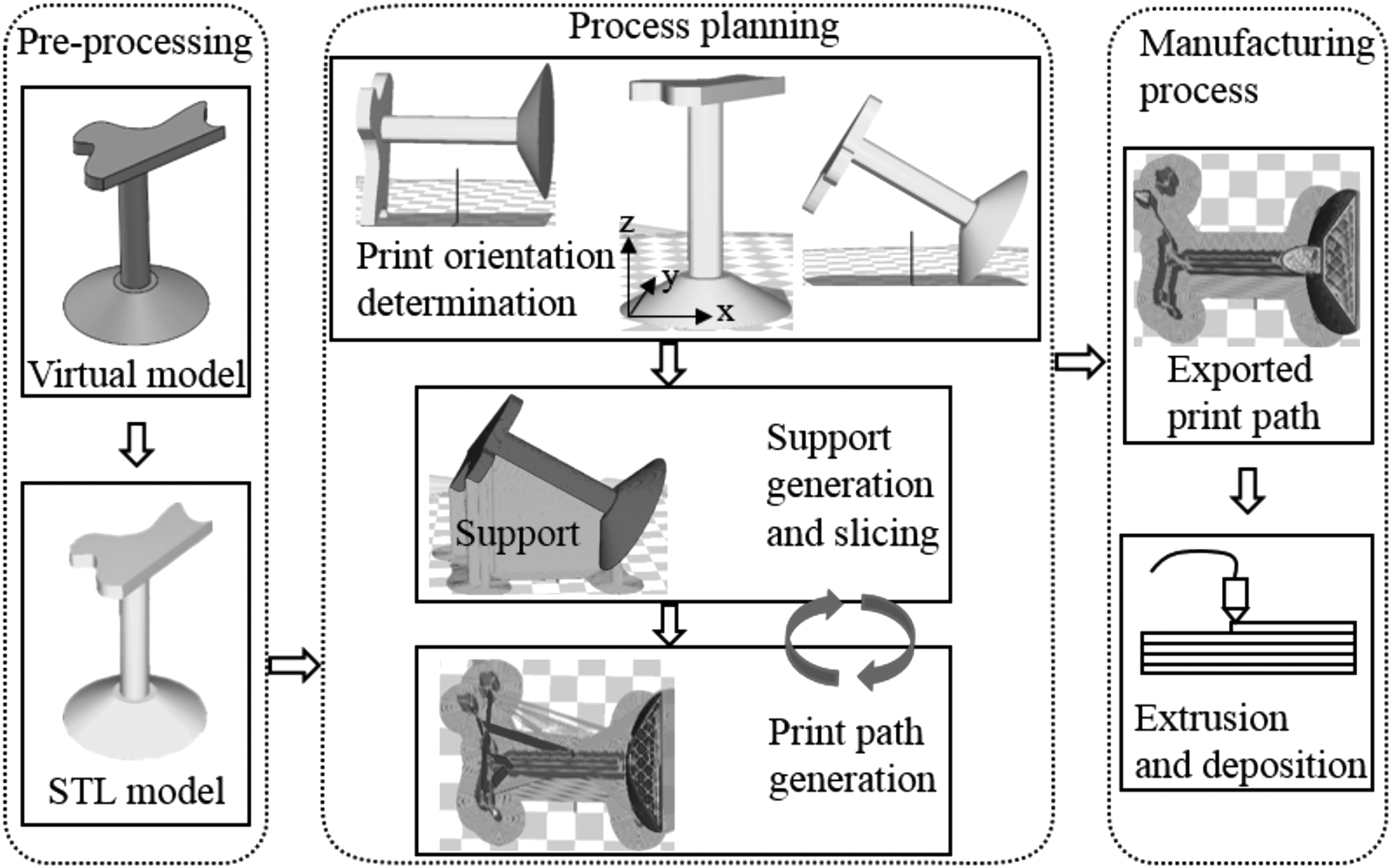
An illustration of process planning in an AM processes. AM, additive manufacturing.
The Concept of PBL and Path Planning
For easier understanding of the proposed support generation method, background about PBL and path planning are illustrated first.
Printable bridge length
PBL means the longest length a 3D printer can print (with satisfactory finish quality) without support structure underneath it. During a printing process, there are many factors (print temperature, print speed, solidification speed, layer thickness) that may influence PBL. Figure 2 shows some printed bridges with different lengths under different process parameters and the same print path direction. Kossel Delta 3D printer was used to print these parts. The build area shape of this Delta 3D printer is circular with maximum width of 180 mm, maximum depth of 180 mm, and maximum height of 300 mm. The nozzle diameter of this printer is 0.4 mm. Polylactic acid (PLA) was used for printing these parts. The dimensions of this model are shown in Figure 3 with depth of 1.0 mm. The exact experimental settings are shown in Table 1.
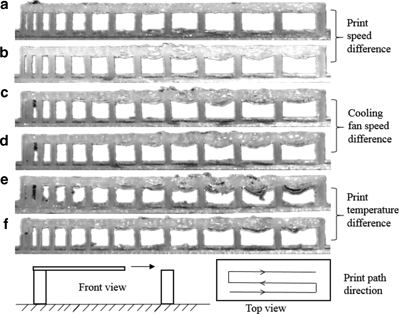
Different printed PBLs in different print parameters. (
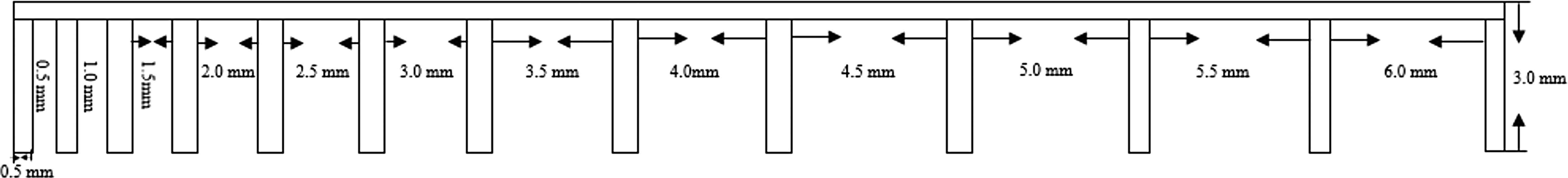
Dimensions of PBL model in Figure 2.
Experimental Settings of Parts Printed in Figure 2
As shown in Figure 2, PBL can be achieved in various lengths when changing process parameters. At the same time, the characteristics (strength, solidity, quality, etc.) of printed parts can also be influenced by these process parameters.30,31 For satisfying the requirements of a product, the process parameters will need to be in a certain range. In this case, the longest satisfied PBL can be experimentally tested according to the required process parameters. And the longest PBL can be accordingly integrated into the support generation method for reducing support material usage and cost in terms of the flat features. For example, Figure 4 shows a concept of generating support for a cubic part based on the longest PBL when the print path direction is as shown in this figure. First, detect the bottom of flat features in 3D models and obtain the contour. Second, generate support of level 1 based on the longest PBL perpendicular to the print path direction. Finally, generate support of level 2 by using the longest PBL distance for support of level 1. This means that the volume of support consumption will be changed when the print path direction is altered.
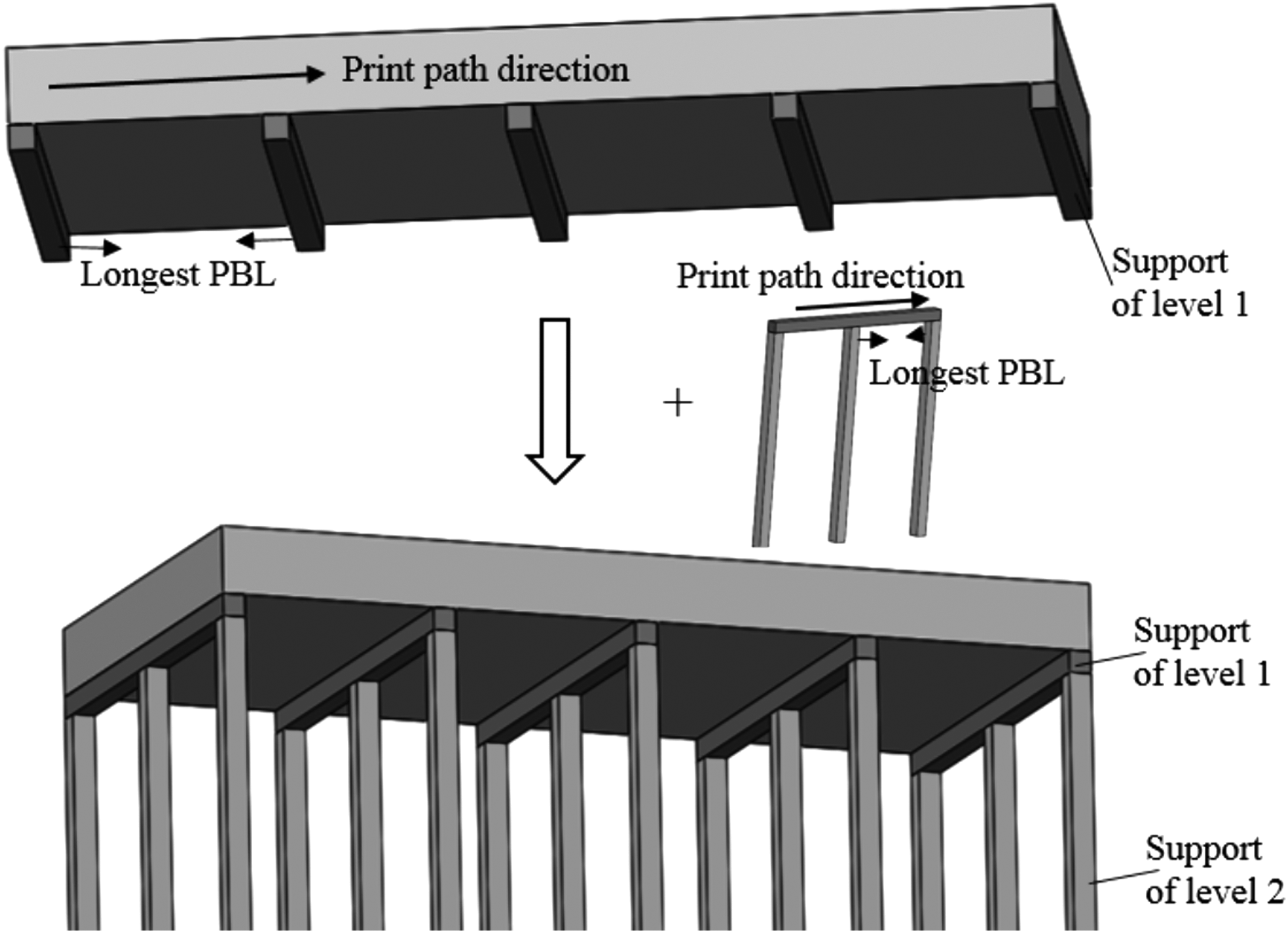
Procedure of proposed support generation method by considering the longest PBL.
Path planning
For a specific layer, the areas to be filled can be achieved through many ways according to different purposes. The team of Jin has carried out a lot of research for the aim of reducing the material usage or improving the final quality by improving path planning.25–29 Generally, most of the 3D printing processes are using two patterns for generating print path. One is direction-parallel method and another is contour method, as shown in Figure 5. In this study, only direction-parallel path is suitable and can be used for applying the longest PBL for generating support structures. Therefore, the path planning in this article is based on direction-parallel path in different rotations, as shown in Figure 5. As can be imagined, the support usage may change when print path direction changes.
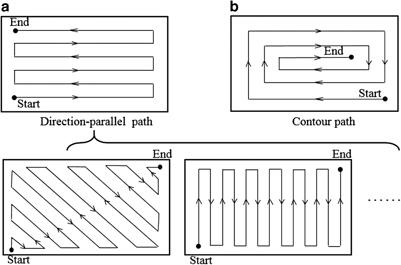
(
Proposed Support Generation Method
In the previous section, PBL and path planning have been introduced. Based on these backgrounds, our support generation method can be divided into seven steps. The illustrations of these seven steps are using an example part shown in Figure 6.
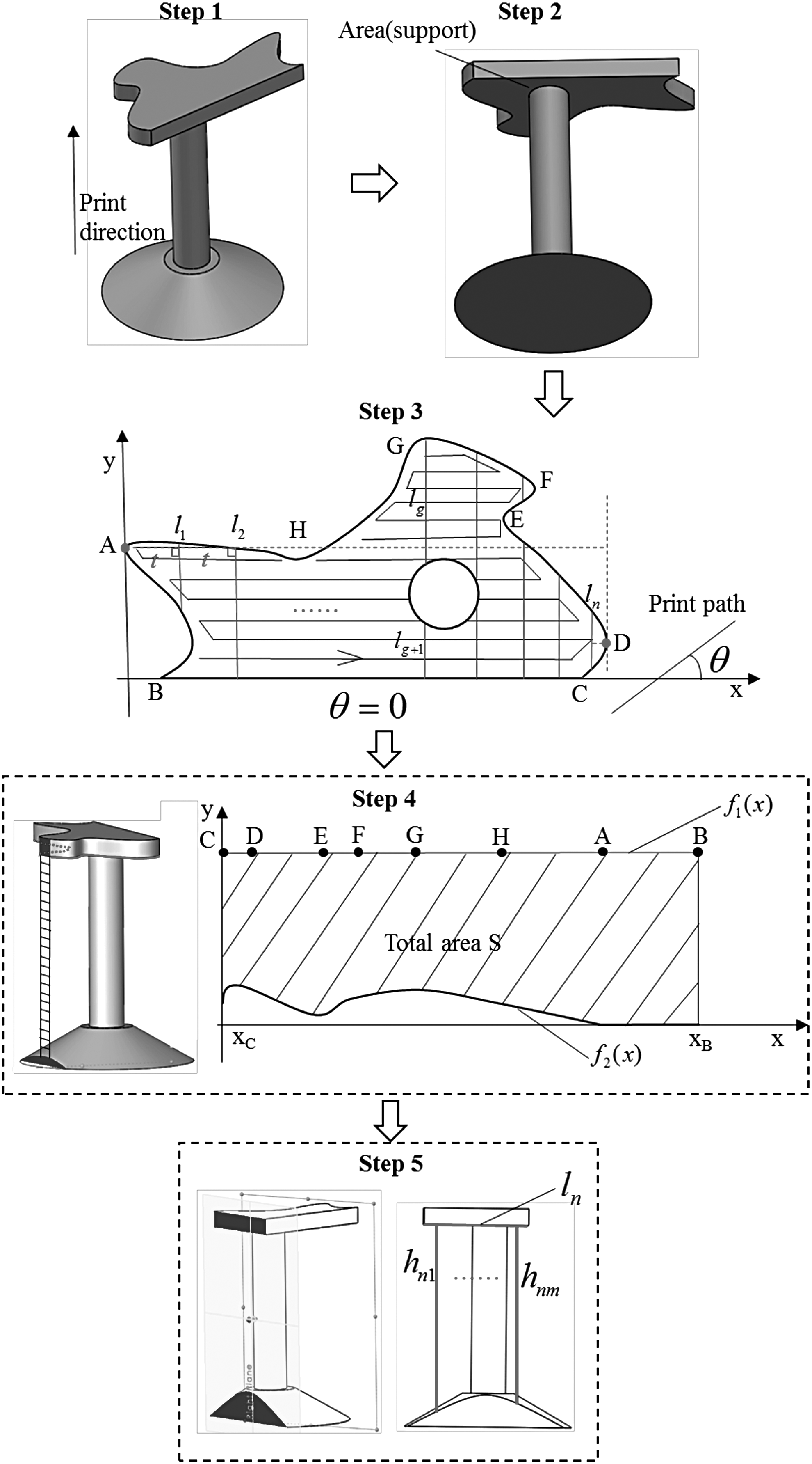
Procedure for obtaining the total usage of support in different print path directions.
where
where
Find the most left (A) and right (D) points on the outside contour of flat area when providing the print path as horizontal. Start from A, draw lines (
The algorithm for finding the best print path direction that consumes the least support is shown in Figure 7. The value of sum in this algorithm can be set at any value as long as it is large enough. After obtaining the optimal print path direction, this print path can be integrated into slicer, thus generating corresponding support based on our method for saving more material and cost.
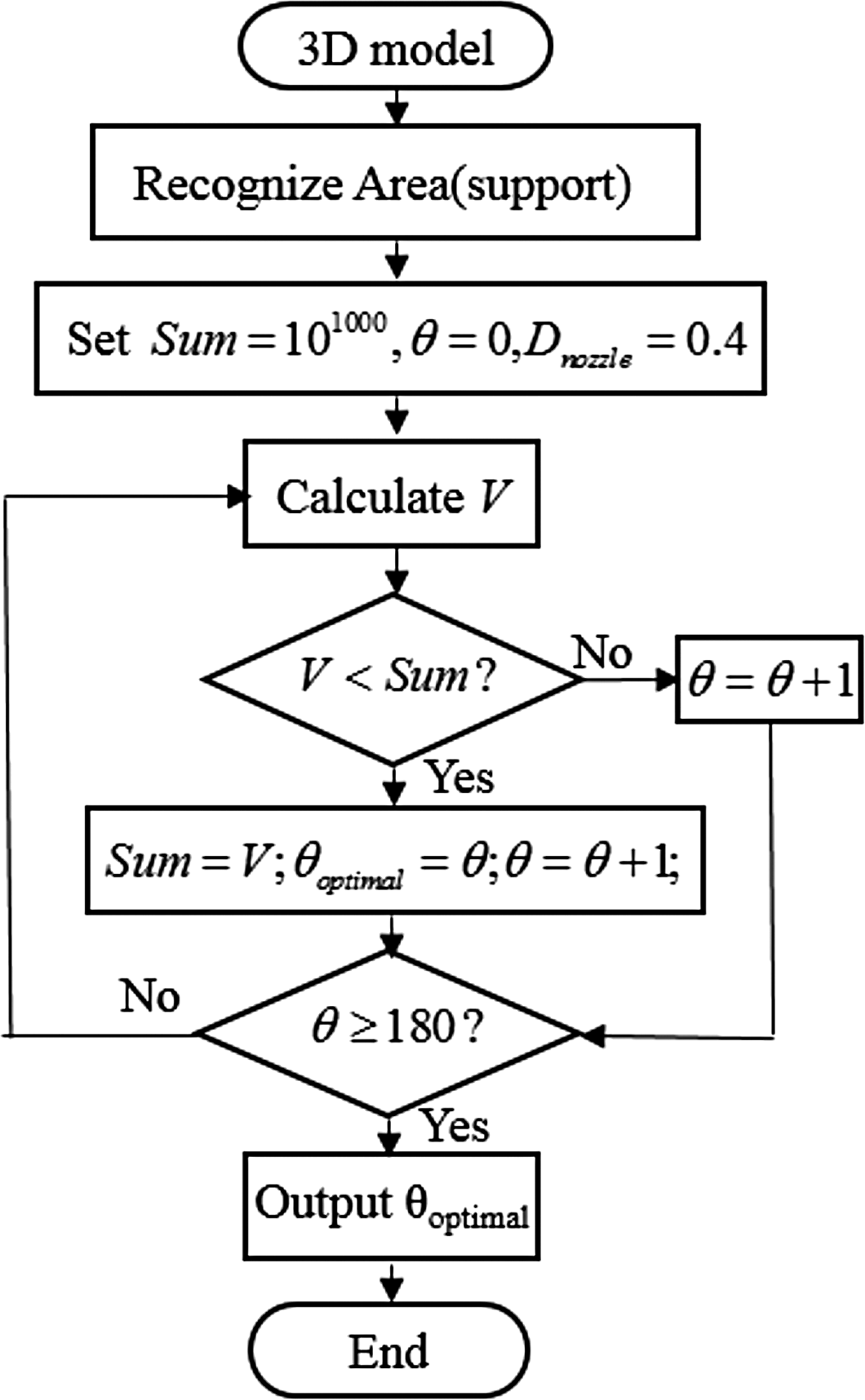
Flowchart of seeking the optimal print path direction.
Demonstration and Discussion
To verify the proposed support generation method, two-part models were tested on a Kossel Delta 3D printer. The build area shape of this Delta 3D printer is circular with maximum width of 180 mm, maximum depth of 180 mm, and maximum height of 300 mm. The nozzle diameter of this printer is 0.4 mm. PLA was used for printing these two parts. The 3D views and dimensions of these two parts are shown in Figure 8.
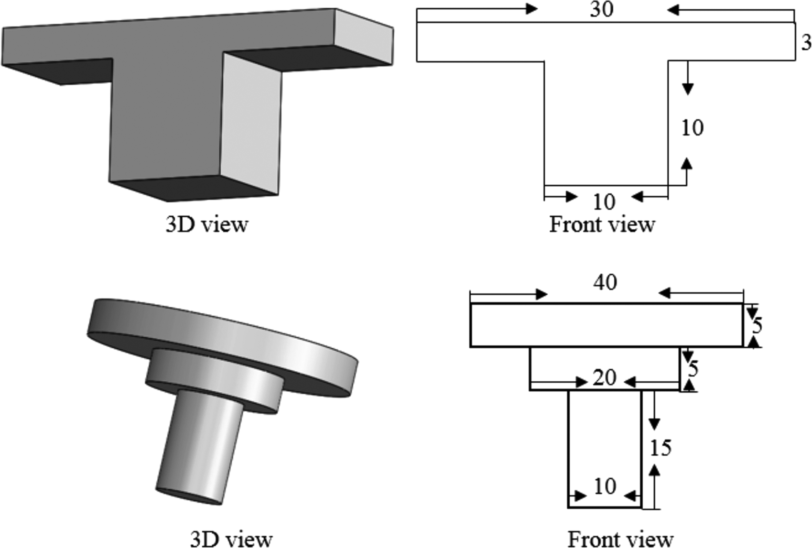
Dimensions of tested two parts (unit: mm).
For obtaining the longest PBL in this Kossel Delta 3D printer, experiments were carried out first. The experiments were conducted with the process parameters of print temperature of 190°C, print speed of 20 mm/s, cooling fan speed of 250 rpm, fill density of 30%, and layer thickness of 0.2 mm (providing that these process parameters are required for some product with satisfactory quality). The results show that the longest PBL can be achieved at 2.0 mm when setting the deformation tolerance within 0.15 mm. Therefore, t can be set at 2 in the algorithm shown in Figure 7, and the corresponding dimensions can be set as shown in Figure 8. The results show that the lowest volume of support usage is when setting print path, as shown in Figure 8. Figure 9 shows the generated supports and the corresponding optimal print path strategies with some sliced layers.
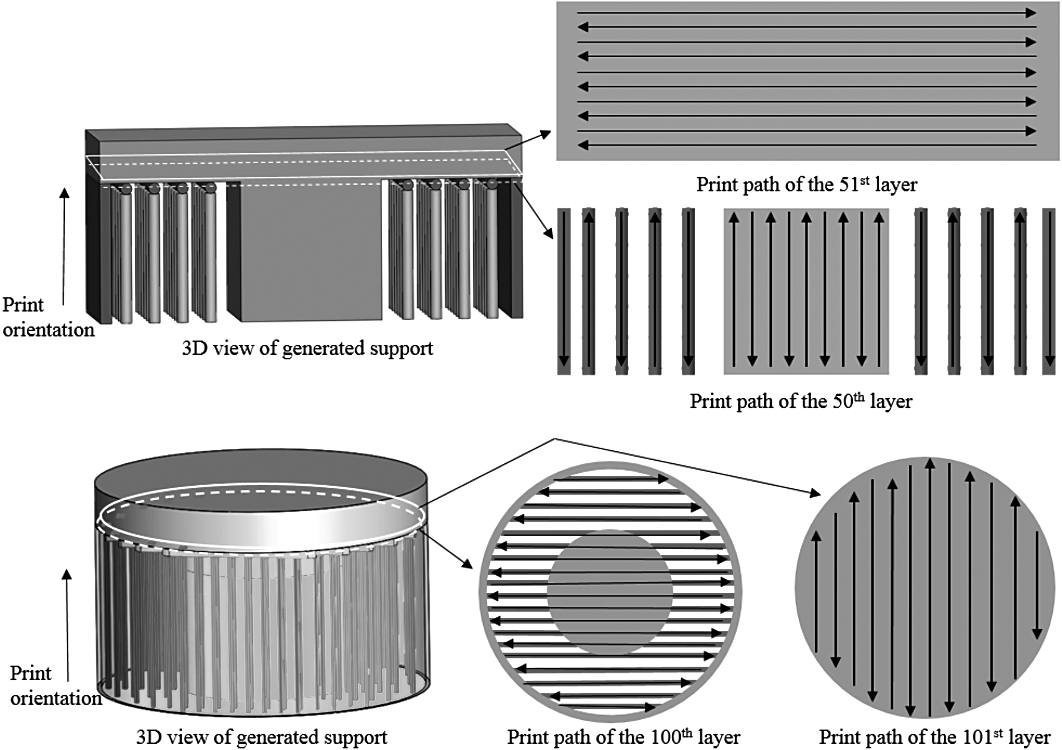
Generated supports and corresponding optimal print path strategies.
For comparison, another two support methods provided by slicer software Cura 15.04 were also used for fabricating the same parts. The results of these three support methods are shown in Figure 10. As can be seen, our new support generation method only consumes 0.4 g support material for the “T” part, whereas line and grid support methods spend 2.1 and 2.3 g, respectively. For the “step cylinder” part, our support method can save three times as much support material as general support methods. In addition, it is easier to remove the support from our method than line and grid methods. In terms of the surface quality after removing the supports, all these three methods leave minor marks on the supported surface. However, our method leaves the least mark area on the surface as our method is based on the longest PBL and has the smallest contact area. This may help reduce the effort on postprocessing and it is easier to be dealt with. The average surface roughness (Ra) has been measured in different support methods by SURFTEST SJ-210, which is a surface roughness measuring tester from Mitutoyo Corporation. 32 As shown in Figure 10, our support strategy has the lowest surface roughness due to the least contact area.
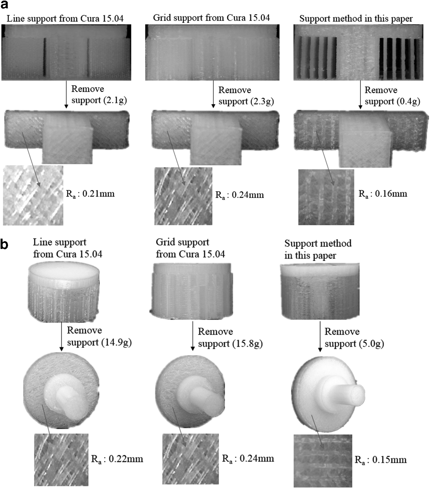
Printed “T” parts
Conclusions
In this article, a method of generating support based on print path planning is proposed based on the longest PBL, aimed at reducing support material consumption in AM of parts with flat features. Traditionally, the print path generation comes after slicing part into layers in the process planning of AM. However, print path is considered before slicing part into layers in this study as print path can make a great contribution to the support usage when integrating the longest PBL into a support generation process. T-shaped and stepped concentric cylinder parts were used as test models for validating the proposed method. Parts are fabricated by three support methods (line, grid, and our proposed methods). The results show that, for the T-shaped part, line support consumes 5.25 times as much support material as our method and grid support consumes 5.75 times. As can also be seen from the stepped concentric cylinder part, our new support generation method can significantly save more material, enabling AM to be a more environmentally friendly and sustainable manufacturing technique. In addition, this method can also reduce the deterioration on the finished surface as it leaves less marks, thus reducing the effort for postprocessing.
Footnotes
Acknowledgments
Help from the engineering librarians at the University of Auckland is highly appreciated. The authors are also grateful for the advice from the Laboratory for Industry 4.0 and Smart Manufacturing Systems members.
Author Disclosure Statement
No competing financial interests exist.