
Abstract
The rapid growth of interest toward concrete digital fabrication reflects the current aspiration for better, smarter, faster, and greener construction means. Among a broad variety of techniques developed by our community, digital casting presents clear advantages regarding dimensional precision, geometrical freedom, and surface finish of the produced elements. In contrast to robotic slip forming, the usage of digitally fabricated formworks requires simpler equipment. It, however, calls for easily shaped formworks, typically best three-dimensional (3D) printed, for example, by fused deposition modeling. While such molds can be easily fabricated with a wide range of commercially off-the-shelf available 3D printers, a shortcoming is the susceptibility of many polymers to environmental stress cracking, particularly when in contact with high pH solutions typical for cementitious materials. This article confirms the problem posed by this type of environmental stress cracking and presents two very effective means of circumventing it: A silicone coating and cyclic olefin copolymer. Apart from this, in the specific case of counterpressure casting (CPC), hydrostatic pressure must be resisted by a powder bed surrounding the formwork. The efficiency of such beds is examined and a particular mixture of sand and lead is shown to be particularly effective, provided its density is regulated to balance stress principles derived from soil mechanics. Presented applications include the successful CPC of thin prismatic formworks with a concrete height up to 3 m as representative of typical interfloor load-bearing elements. The combination of counterpressure and stress control is shown to be essential for such achievement, highlighting the potential of this approach as a viable member of the concrete digital casting family.
Introduction
Digital fabrication with concrete is rapidly gaining interest and a variety of approaches have been proposed, for example, extrusion printing,1–3 smart dynamic casting,4–6 mesh mold,7–9 shotcreting,10–12 and powder bed printing.13,14 All these processes have their respective advantages and shortcomings. Overall, however, the question of reinforcement appears to represent a main challenge, particularly for extrusion printing, which is the widest spread of all these processes.15–19 Thus, approaches in which reinforcement may be preplaced and the concrete casted, without causing failure of the mold, can be seen as offering substantial advantages in terms of easy regulatory adoption for structural elements.4,20,21
The work presented in this article is a follow-up of a project realized in 2017, which consisted in producing a topology-optimized, high-performance, fiber-reinforced concrete (HPFRC) canoe. 22 The canoe's 0.8-mm-thick formwork was three-dimensional (3D) printed by fused deposition modeling (FDM) using transparent polylactic acid (PLA) filament. 23 To minimize the risks of failure of the formwork, a special casting procedure of the canoe's structure was developed: counterpressure casting (CPC). This can be considered a member of the broader family of digital casting processes.4,20,24 CPC consists of placing the formwork inside a wooden box gradually filled with sand, the level of which is kept equal to the rising concrete during the casting by taking advantage of the translucid aspect of the formwork. Sand acts as a counterpressure to the hydrostatic pressure of concrete, therefore stabilizing the formwork during the casting process and reducing the formwork's load. Special attention was paid first to formulating the HPFRC to assure a continuous flow in the formwork without clogging and second to the casting procedure itself to avoid entrapped air pockets.25,26
While adding a certain complexity to the casting process through the handling of the counterpressure material, this approach is beneficial in comparison with both traditional 27 and other digital casing approaches. The geometrical freedom of FDM-printed formworks combined with topology optimization allows an important reduction of material usage and cost in comparison with traditional wooden formworks. 28 When compared with other digital formwork casting approaches such as eggshell 21 or the usage of thin tensioned foils for folded structures,29,30 CPC brings the non-negligible advantage of avoiding the need to finely control the setting and hardening of concrete through setting on demand,30,31 allowing a much wider choice of casting materials.
However, during the realization of the concrete canoe project, important formwork failures and concrete leakages were observed on both casting prototypes and the canoe itself. Expected stresses were considerably lower than what would have been needed for failure of the 3D-printed PLA. While these failures could not be addressed upstream at that time due to the project time constrains, the follow-up work presented in this article investigates the origin of these failures and brings practical solutions to avoid them, thus fully enabling the potential of CPC of thin FDM-printed formworks.
Materials and Methods
FDM 3D-printed formworks
Two types of plastic filaments were used during this study to produce the tested elements: transparent PLA NX-1 from extrudr (Lauterach, Austria) and transparent cyclic olefin copolymer (COC) from Creamelt (Rapperswil-Jona, Switzerland). Two geometries were tested during this study: tubular and prismatic.
Tubular samples were printed with an inner diameter of 60 mm and a wall thickness of either 0.8 or 0.4 mm. Such samples were first printed in two 60-cm-long parts and cold welded together using dichloromethane, as can be observed in Figure 2, left. As it became clear during the study that failure of the tubes was always occurring at their bottom, the 3D-printed part of the tubes was then reduced to a height of 150 mm (e.g., Table 1) and connected to a rigid PVC tube of similar diameter to reach an equivalent hydrostatic pressure of concrete. This strategy of adding a PVC tube on top of a 3D-printed sample was also used for the prismatic samples (Fig. 1).
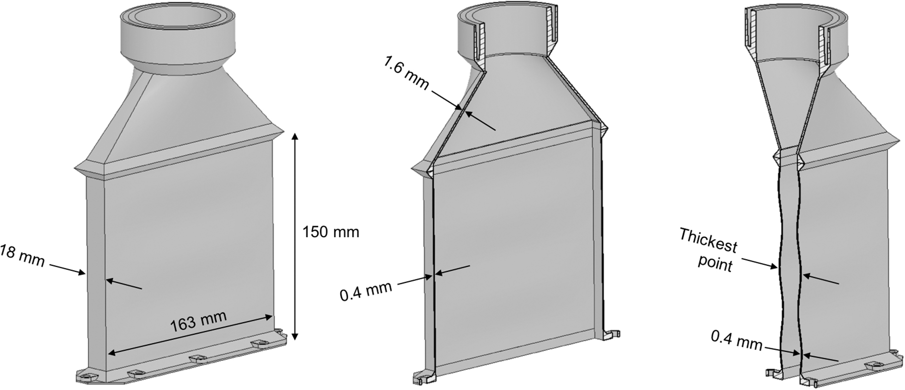
Prismatic sample geometry. The effective dimension of the thickest point was 25 ± 2.0 and 28 ± 0.3 mm, respectively, for PLA- and COC-printed formworks. COC, cyclic olefin copolymer; PLA, polylactic acid.
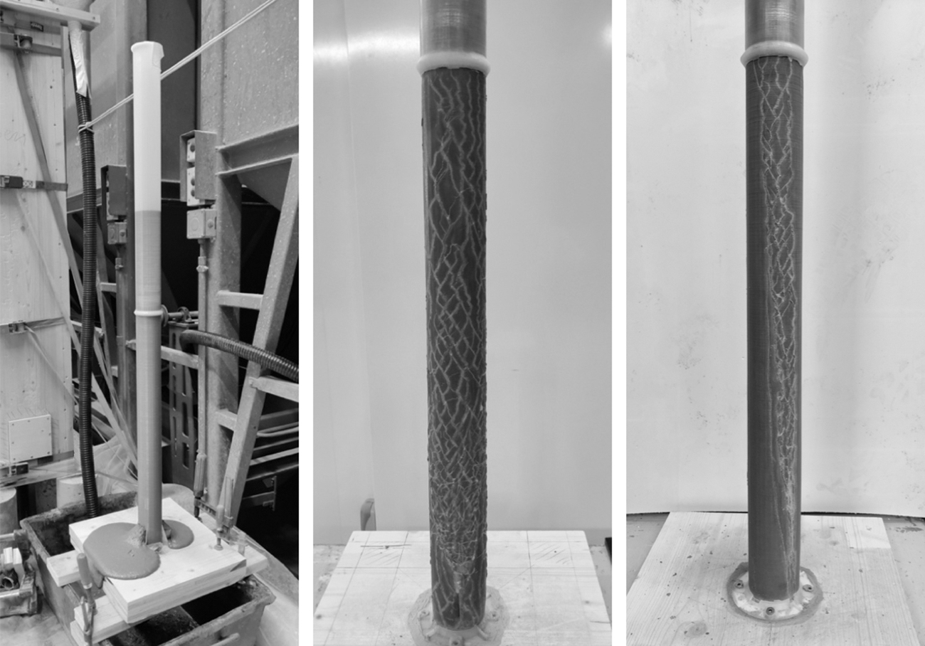
Preliminary tests on PLA tubular formwork. Left: formwork failure without CPC at a concrete height of 82 cm. Center: formwork failure with sand CPC. Right: formwork failure with sand and lead granules CPC. CPC, counterpressure casting.
Short Tube Formwork Test Results
The prismatic shape was selected to obtain formworks, the deformations of which resulting from hydrostatic pressure of cast concrete would be amplified and easier to measure in comparison with a tubular shape that only presents Hoop stresses in the given configuration. However, FDM printing of straight thin walls is challenging as the warping of the plastic during the printing process tends to provoke an uncontrollable buckling resulting in a random barreling of the printed walls. To minimize this effect and obtain more reproducible dimensions, a defined wave pattern was introduced in the two large walls (163 × 150 mm) of the formwork (Fig. 1, right) to control the barreling effect. This proved to be effective and resulted in effective dimensions of 25 ± 2.0 and 28 ± 0.3 mm, respectively, for PLA- and COC-printed formworks at their thickest point, as shown in Fig. 1, right.
Additional information regarding the 3D printing parameters of the formworks can be found in the Supplementary Data of this article.
Inverted three-point bending tests
To evaluate the role of environmental stress cracking on the strength of our 3D-printed molds, we used a three-point bending test. Modifications of this test were made for a still-to-be published study specifically examining environmental stress cracking of various 3D-printed polymeric materials. The most important aspect of the test is the measurement of the flexural stress and strain curve on standardized samples, loading span, and speed as described in EN ISO 178. The major modification of the standardized setup is the vertical inversion of the loading points to have the sample's face under tension facing upward allowing to keep it in contact with a liquid during the test by depositing it on its surface.
The printing parameters of the 4 × 10 × 80 mm samples were chosen to better represent the load underwent by the formwork under hydrostatic pressure. Indeed, the orientation of the print and the filling of the three-point bending tests were matched to correspond as closely as possible to those of the formworks in which the fused plastic is deposited in a monodirectional orientation parallel to the printing bed and ultimately perpendicular to the horizontal hydrostatic pressure of concrete.
For each case considered, three samples were measured from which the average and the standard deviation were determined. Samples were tested in their dry state, in contact with water, or in contact with a 0.1 M NaOH solution used to represent an alkaline environment similar to fresh concrete.
As shown in the latter, the strength of PLA samples was severely affected by the NaOH solution, which is why we also tried applying different coatings to protect the PLA: two types of transparent acrylic varnishes, latex and molding silicone (all off-the-shelf commercial products). The coating of the samples was realized by dipping one of their 4 × 10 mm faces in the respective coatings and letting them cure accordingly to their respective supplier defined curing times in a vertical position before testing. Coating minimal curing times were as follows: molding silicone = 1 h, latex = 4 h, and acrylic varnishes = 12 h.
When used in combination with printed formwork elements, the coating material was poured inside the formwork that was then manually rotated to assure a complete coating of its inside. The formwork was then suspended in a vertical position to allow the excess of coating material to drip off the formwork until its' complete curing.
Concrete casting
Concrete formulation and mixing procedure
The work presented in this article was realized with the same HPFRC formulation used in 2017 to produce the topologically optimized concrete canoe skelETHon. 22 This formulation was originally developed and tested in 2016 to produce a topology-optimized ceiling element. 25
Minislump test
Minislump tests were performed on each freshly batched HPFRC mixture to assure quality control. The cone used for the minislump has a height of 6 cm, a base diameter of 10 cm, and a top diameter of 7 cm. The acceptance criterion for casting was a spread in between 22 and 25 cm in diameter. The lower value assured a good workability of the mixture, while the upper one was noticed to be the limit above which fiber segregation was occurring.
From these measurements we can calculate a yield stress using the equation of Roussel and Coussot for a large spread regime 32 and the one from Pierre et al. for the intermediate regime. 33 With the mortar's density of 2400 kg/m3, we get yield stresses between 31 and 16 Pa in the first case and between 30 and 16 Pa in the second.
Counterpressure casting
Two different counterpressure materials were tested during this work: an all-purpose sand; and a mixture of quartz sand and lead granules. The second counterpressure material was obtained by mixing together a monosized 0.1–0.45 mm quartz sand together with lead spherical granules with a diameter of 2.5 mm. The mass proportions of this mixture were 79.2% of lead granules for 20.8% of quartz sand (33.5% and 66.5%, respectively, by volume). The purpose of this mixture was to increase the bulk density of loose sand acknowledged to have a value between 1.4 and 1.6 depending on its compaction. 34 The obtained sand and lead granule mixture has a bulk density value of 4.8 allowing to increase the counterpressure on the formwork in comparison with loose sand alone, as explained in the Preliminary PLA Testing section of this article.
When casted in a counterpressure configuration, the formwork was installed in a fitting wood box, one side of which was made out of transparent plexiglass allowing to observe and match the concrete and counterpressure material levels during the casting. During the casting, the box was gradually filled with counterpressure material to always keep a height difference between concrete and counterpressure material levels under 5 cm. For formworks that were coated with nontransparent materials such as molding silicone, a metallic weight attached to a string was used to sound the levels of concrete and counterpressure material. Once the formwork was completely filled, it was covered with an additional of 5 to 10 cm of counterpressure material and let to cure for at least 24 h before removing it from the box.
After removal of the cured element, the structural soundness of the formwork was assessed and final dimensions were measured. Variations with respect to the initial dimensions are presented in the Results and Discussion section of this article. They are given, respectively, to the tubular samples' diameter (60 mm) or to the prismatic formwork maximal deflection of its 163 × 150 mm walls in comparison with the dimensions presented in the FDM 3D-Printed Formworks section.
Results and Discussion
Preliminary PLA testing
To investigate the failure mechanics of PLA formwork, several tubular samples were casted (Fig. 2).
The first tube (Fig. 2, left) was casted without any counterpressure material. This tube showed a failure at its bottom for a concrete height of 82 cm, representing a hydrostatic pressure of 19.3 kPa with a concrete density of 2400 kg/m3. At this particular hydrostatic pressure, the resulting Hoop stress at the bottom of the tube can be estimated to be equal to 146.7 kPa, representing 0.28% of the 53 MPa nominal tensile strength by the filament manufacturer. Using the theory of plates and shells 35 for thin-walled cylinders, localized lateral bending on the formwork wall also leads to tensile bending stress on the concrete-formwork interface in the vicinity of supports. Such supports may be ring stiffeners, but can in a worst-case estimation also be localized support points of sand particles in the counterpressure-cast material, especially since localized bending stress for this cylinder geometry is influenced by the support conditions at 1 cm from such support points (Supplementary Data). Plate and shell theory expects maximum tensile bending stress at the support point in case of stiff supports and this leads to a tensile bending stress at the interface of 1.3 MPa, this being 2.5% of the filament strength. Thus, even in this worst-case calculation that applies to both counterpressure and normal casting, the applied load is substantially lower than the material strength. This first-order analysis can be refined by considering the adhesion of the mortar onto the mold walls and the reinforcement, but as shown in Appendix A1, none of these effects fundamentally changes the conclusion. This result points toward a considerable chemical vulnerability of PLA to concrete caused by environmental stress cracking and failure of the formwork for relatively low hydrostatic pressures if no counterpressure or coating measures are put in place.
All tubes casted with sand as counterpressure material showed a similar failure pattern presented in Figure 2, center. The failure only occurred on the lower halves of the tubes originating from a set of cracks at their bottom as observed in the sample without counterpressure material described above. The rest of the failure presents an aspect of crack propagation mechanism resulting in an integrity failure of the lower halves of the tubes and a diametral deformation of up to +5.3 mm. The crack propagation appears to be stopped at the welding joint between the two halves of the tubes while the upper halves remain undamaged. These results indicate that the usage of sand as counterpressure material is not sufficient to prevent a 0.8-mm-thick PLA formwork failure due to environmental stress cracking for concrete heights equal or greater than the one tested (1.2 m).
In a trial to counteract the previously described failures, a first approach was implemented consisting in artificially increasing the sand density to increase the counterpressure on the formwork. According to soil mechanics, the vertical and horizontal pressures exerted by a column of loose sand are not equal in contrast to a column of liquid, and their relationship is described as follows
34
:
where
Considering that loose sand has a bulk density of 1400–1600 kg/m3 depending on its compaction, we can deduce that sand can only counteract 26% to 33% of the concrete hydrostatic pressure. Therefore, to match the counterpressure on the formwork to the hydrostatic pressure of concrete, a mixture of sand and lead granules with a bulk density of 4800 kg/m3 was used as counterpressure material (please refer to the Minislump Test section). Unfortunately, the tubes casted in this configuration presented the same type of failure (Fig. 2, right) as the ones casted with only sand (Fig. 2, center), with a diametral deformation measured of up to +1.7 mm.
Environmental stress cracking is not only linked to the applied stress but also to the time-resolved chemical degradation of PLA in alkaline environments.36,37 Therefore, even a slight difference between the counter and hydrostatic pressures could lead to the weakening of the formwork and its failure during the concrete's setting time frame, measured by isothermal calorimetry to be about 5.5 h for the used HPFRC. While the diametral deformation seems to be reduced by the increase of counterpressure, its nonzero value shows that regardless of the theoretical matching of counter and hydrostatic pressures, a deformation was still able to occur after the formwork's failure. The origin of this phenomena could be linked to the additional compaction required to attain a full mechanical lock of the counterpressure material and would be worth looking into from a soil mechanics perspective.
These last results showed that PLA cannot be successfully used as concrete 3D-printed formwork material without addressing its weakness to the alkalinity of concrete and finding an appropriate protective coating to mitigate the effects of environmental stress cracking. This led us to perform mechanical investigations regarding these aspects by using the three-point bending testing.
Environmental stress cracking attenuation investigations
To investigate the vulnerability to stress-induced corrosion in the alkaline environments of PLA and COC 3D-printed parts, as well as to find a suitable coating for protecting PLA, inverted three-point bending tests were performed. The results of these tests are reported in Figure 3.
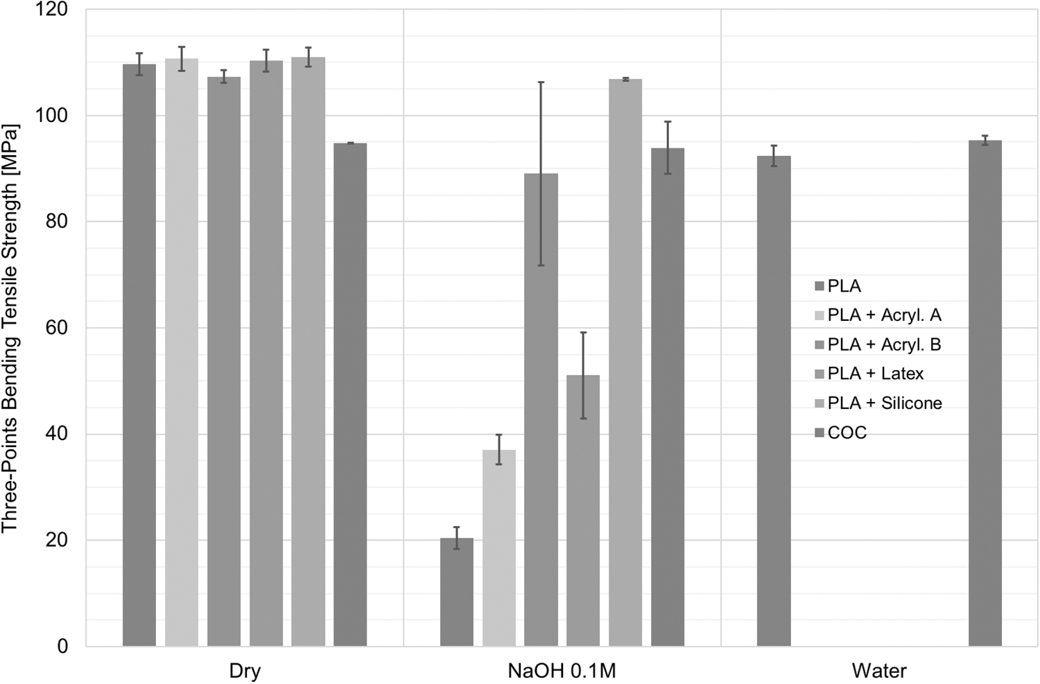
Three-point bending test results. Samples were tested in the following three states: dry, while in contact with water, and while in contact with a 0.1 M solution of NaOH (pH = 13). For each data set, the given result is equal to the average of three samples, while the error bars represent the standard deviation.
While uncoated dry PLA presents an average flexural tensile strength of 109.7 MPa, a drop of 16% and 81% of this value is observed when the sample is, respectively, in contact with water and 0.1 M NaOH solution (pH = 13). Even if PLA is not considered to be soluble in water, it undergoes a degradation driven by the hydrolysis of the polymer's backbone by water molecules. 38 In a highly alkaline environment, this hydrolysis is accelerated by the high concentration of OH− ions.36,37 Combined with the tensile stress underwent by the samples during the test, this explains the losses in tensile strength due to environmental stress cracking. The pH of fresh concrete's pore solution varying between 12 and 13, it is safe to assume that the failures of PLA-printed formwork described above resulted from the same phenomena, explaining the abnormally poor mechanical resistance. The observation of distinctive cracks throughout the three-point bending samples in contact with alkaline solution also supports this interpretation.
Among the tested PLA coatings, none brought a significant increase in flexural tensile strength in the dry state compared with the uncoated sample (Fig. 3), allowing us to assume that the results obtained while in contact with alkaline solution are only dependent on the protection efficiency of the coatings in this configuration.
The results obtained for the coated PLA samples in contact with the 0.1 M NaOH solution show a considerable vulnerability of acrylic varnishes and latex coatings to the alkaline environment, even if the acrylic varnish B seems to improve the resistance compared with both the acrylic varnish A and the latex. Nevertheless, the important standard deviation obtained for this particular varnish does not offer much confidence in terms of achieving a robust protection.
Results obtained for the silicone-coated PLA samples in contact with 0.1 M NaOH solution do not show any significant decrease in tensile strength in comparison with the dry uncoated ones. Therefore, this particular coating is fully adequate to protect PLA from highly alkaline solutions. It was therefore chosen for application on the inside of printed formworks filled with concrete as presented in the Enabling Failure-Free CPC section of this article.
Apart from the question of PLA coatings, Figure 3 also shows that COC samples did not present any significant variations in tensile strength when in contact with water or 0.1 M NaOH solution. Combined with the relative ease for FDM printing with this material, these results identify COC as a very promising candidate for concrete formwork 3D printing, as presented in the Enabling Failure-Free CPC section of this article.
Enabling failure-free CPC
Tubular formworks
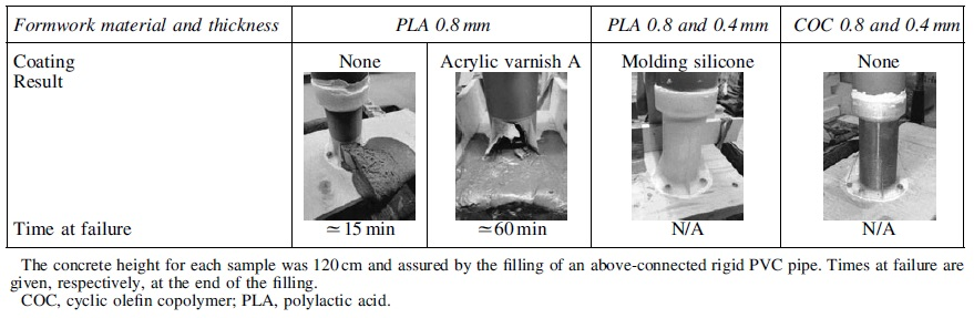
Following the results obtained from the three-point bending tests, a first series of tubular formworks were casted without counterpressure, as presented in Table 1.
The first formwork made of uncoated PLA was tested to verify that the new setup using shorter 3D-printed parts and PVC tubes was reproducing the same type of failure as the fully 3D-printed tubes presented in the Preliminary PLA Testing section. The observed failure presented in Table 1 confirmed this hypothesis. In addition, due to a faster concrete filling rate in comparison with the samples presented in the Preliminary PLA Testing section, the time dependency of the failure process was observed as it occurred 15 min after the entire filling of the 120-cm-high sample highlighting the time-dependency nature of PLA environmental stress cracking.
To verify the reproducibility of the three-point bending tests, a tubular sample coated with acrylic varnish A was tested. The result confirmed the vulnerability of this coating to concrete alkalinity as the failure occurred about 60 min after the filling of the formwork. The 45-min difference with the uncoated formwork could correspond to the additional time required to the degradation of the coating.
Both silicone-coated PLA and COC tubes did not present any failures or measurable deformations during these tests. These results confirm that molding silicone is an adequate coating that can be used to protect PLA formworks from environmental stress cracking and failure, therefore enabling the full potential of this versatile 3D printing material for usage in concrete digital fabrication. The absence of failure on COC 3D-printed formworks demonstrates the chemical resistance of this material in alkaline environments observed during the three-point bending tests.
Prismatic formworks
The results obtained on prismatic formworks are presented in Tables 2 and 3, respectively, for silicone-coated PLA and COC. These results demonstrate that CPC can be successfully used to avoid failure of thin 3D-printed formworks when environmental stress cracking is prevented.
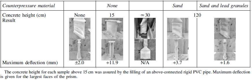
Polylactic Acid Molding Silicone-Coated Prismatic Formwork Test Results
Cyclic Olefin Copolymer Prismatic Formwork Test Results
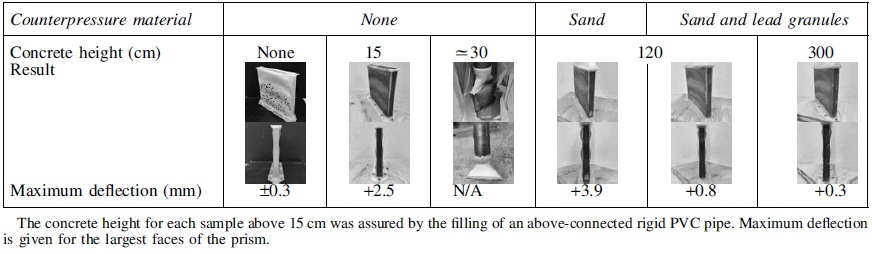
While the silicone-coated PLA formwork shows a barreling deformation in comparison with the COC one for the 15-cm-high samples casted without CPC, the other samples show a similar behavior for both materials. One hundred twenty-centimeter-high samples casted without counterpressure exhibit failure at concrete heights of about 30 cm. This similar behavior between the two materials can be explained by their relatively similar tensile strength, as presented in Figure 3, in addition to the geometry of the formwork having been kept identical.
Samples casted with CPC did not present any failure, while a variable deflection of the prisms' largest faces was observed, as presented in Tables 2 and 3. For both formwork materials, this deflection is considerably reduced by using sand and lead granules rather than sand only as counterpressure material. When compared with the failure of prismatic samples discussed above, these results show that sufficient counterpressure enables the casting of thin FDM-printed formworks with a geometry otherwise prone to deformation and failure. These results also demonstrate that the approach of increasing the counterpressure material bulk density, presented in the Preliminary PLA Testing section, reduces the dimensional changes of this kind of formworks. In addition, using the maximum deflection of the samples with 1.2 m concrete height, it is shown in the Supplementary Data that friction of the counterpressure material on the walls of the sand-bed box does not significantly reduce vertical sand-bed pressure in this case. However, the same calculation implies that vibrations can significantly modify the pressure state in the sand-bed, implying that in further investigations a vibrated box may lead to a more robust sand pressure and reduce the need for high-density counterpressure material.
From an aesthetic point of view, the surface finish obtained with silicone-coated PLA and COC formworks is, respectively, presented in Figures 4 and 5. It is important to note that while the COC formwork shows a mildly rough surface finish typical to FDM-printed formworks where the printing layers are observable, the silicone-coated PLA formwork shows a surprisingly pleasing, slightly glossy, and totally smooth finish. This result is of particular interest as no additional surface treatments are required on either of the formwork materials, allowing a choice of which surface finish is best suited for the desired application.
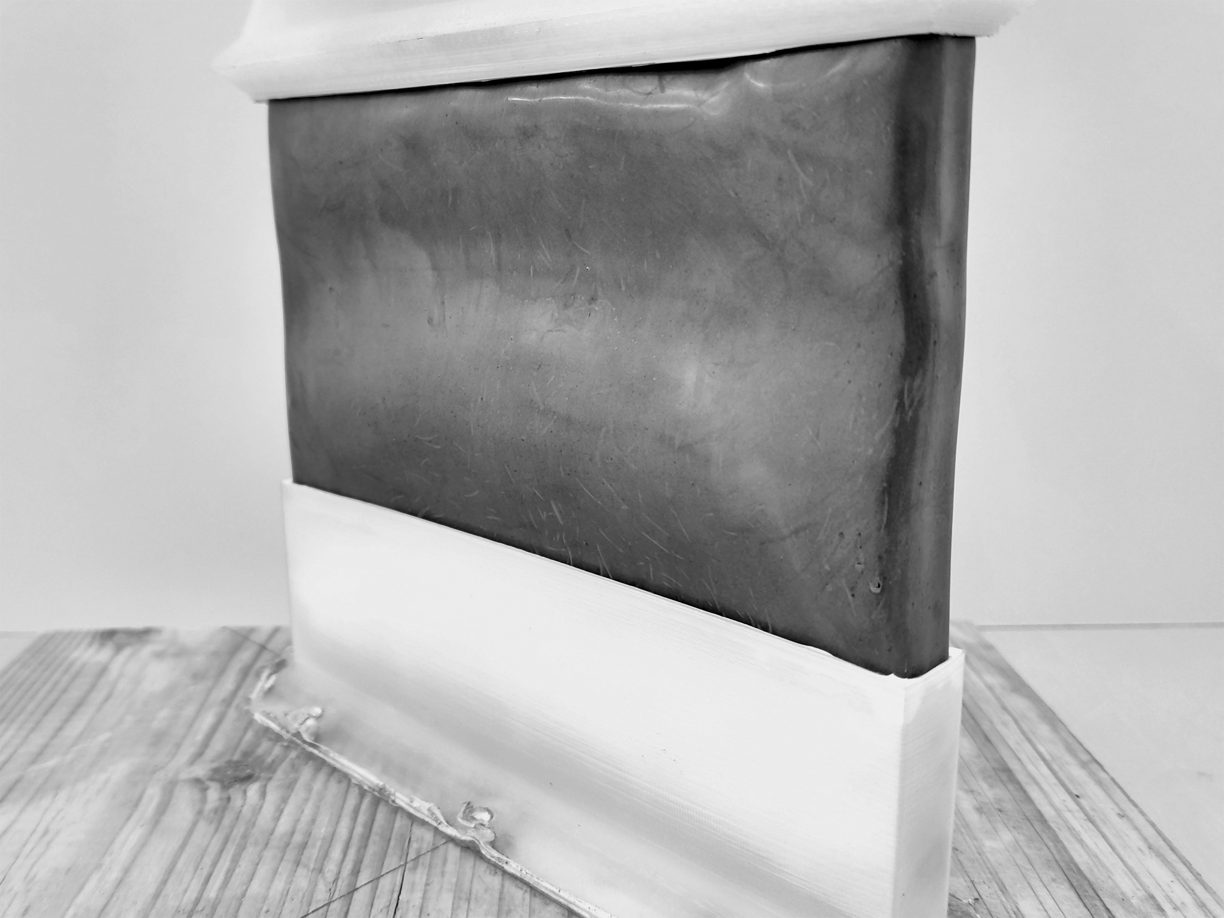
Molding silicone-coated PLA prismatic sample surface finish.
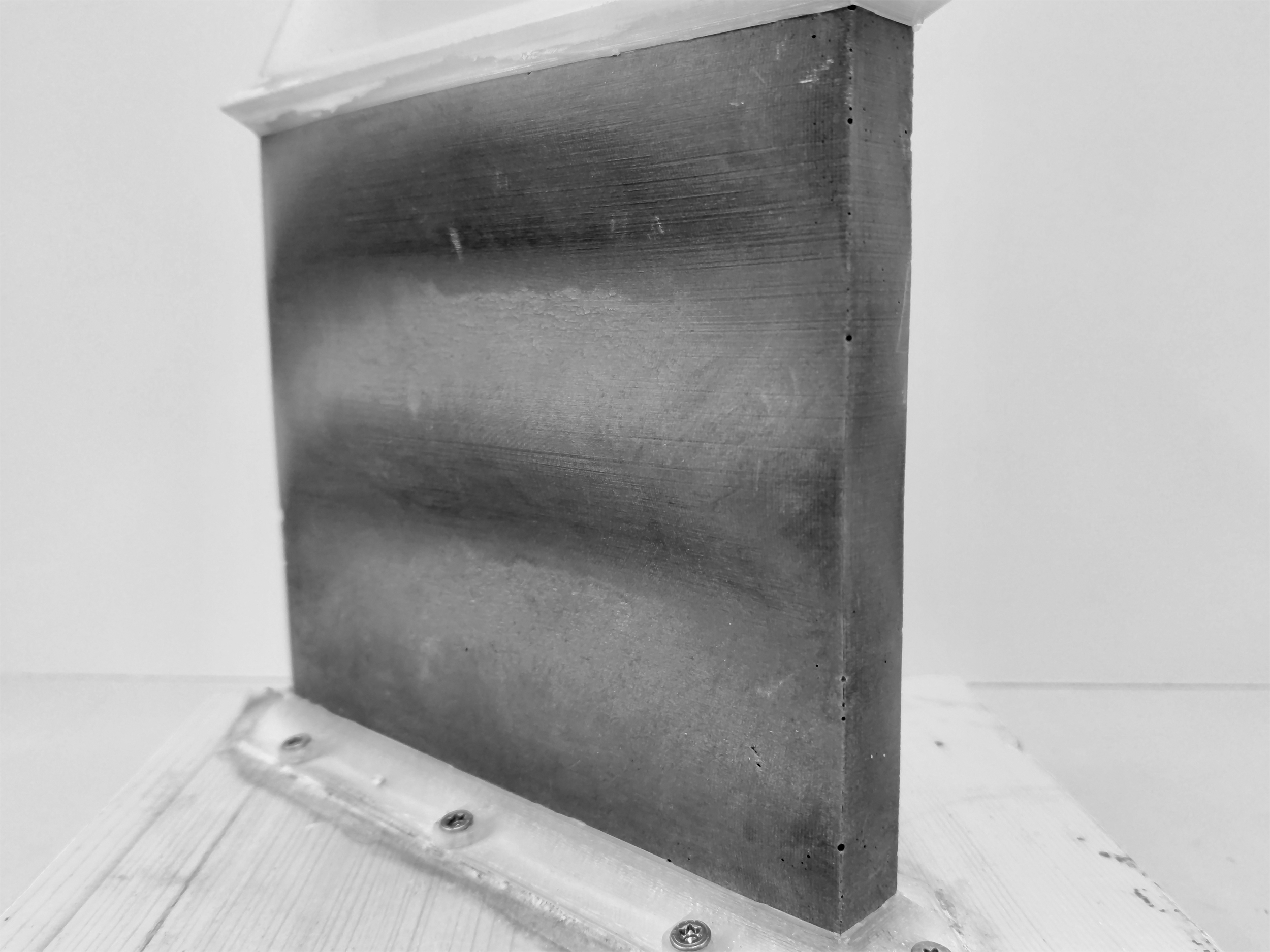
COC prismatic sample surface finish.
The successful casting of a COC prismatic sample withstanding 3 m of concrete hydrostatic pressure without failure or major deformation proves that this technique can be vertically upscaled and used to produce elements such as interfloor columns. It enables the production of such elements with the geometrical freedom of FDM printing and with the liberty of using any kind of concrete that would be able to flow without clogging in the chosen formwork and without having the constraint of controlling its setting and hardening behavior as casting takes place. While the integration of reinforcement in such elements would bring an additional complexity, it would broaden the range of structural performances that could be achieved. The interesting combination may also involve the combination of fibers and established continuous reinforcement systems, included but not limited to steel rebars. This technique brings additional promising opportunities into the growing concrete digital casting community and offers reasonable solutions to ensuring structural integrity for highly loaded elements.15,16,39,40
Outlooks
Several outlooks are worth mentioning regarding CPC:
While the usage of sand and lead granules as counterpressure brought a significant improvement in dimensional changes, its use remains delicate from both health and recycling points of view. Indeed, working with this material produces a considerable amount of dust potentially contaminated with lead. Strict usage of dust removal systems and personal protective equipment such as dust masks, gloves, and goggles is therefore imperative. The disposal and recycling of this material also require special attention as it needs to be treated in a dedicated way. The usage of a lead-free counterpressure material would therefore be something worth looking into. This could be, for example, achievable by using a sand and steel granule mixture in proportions that would match the desired bulk density (e.g., ratios of 85/15 by mass or 52/48 by volume, respectively, for carbon steel spherical granule diameter 2.5 and 0.1–0.45 mm quartz sand would give a mixture with a bulk density of 4800 kg/m3). All performed tests were realized on relatively vertical formworks. Therefore, the question of the reliability of this technique on formworks containing horizontal overhangs would need to be assessed as the counterpressure material has limited flow properties. If this technique were to be upscaled for industrial applications, it remains mainly suitable for off-site prefabrication of geometrically complex elements.
Finally, as a more general outlook beyond the strict case of CPC, the very good performance of both silicon-coated PLA and COC is promising for other digital casting applications. In particular, for eggshell, 21 it would allow to work with a less tight control on the setting time, making it easier to place the material in a reliable and robust way.
Conclusions
CPC has the potential of becoming a well-appreciated and extensively used digital fabrication process in its own right. Important advantages that it has to offer include the easy inclusion of reinforcement, reduced reliance on a tight control of concrete setting and hardening kinetics, excellent surface finish, great ease of use, as well as a large range of formwork geometries accessible by FDM printing.
This article demonstrates that two conditions are needed to achieve this potential. First, the density of the powder bed must be selected to offer enough resistance to the hydrostatic pressure exerted by the concrete in the printed formwork. Second, the formwork must be resistant to environmental stress cracking that results from a combination of high pH of cementitious materials and from tensile stresses in the formwork caused by the hydrostatic pressure.
The two solutions presented to the problem of environmental stress cracking can find a much broader application in digital casting processes relying on 3D-printed formworks. All in all, those solutions as well as the general solutions presented for CPC should open the door to a wide variety of applications in the concrete digital fabrication community, highlighting once again the concept of “complexity for free.” 41
Footnotes
Acknowledgments
The authors are thankful to Heinz Richner and Andi Reusser for their help in carrying out the experiments. The authors are also thankful to Andrei Jipa for many fruitful exchanges on the topic of casting concrete in digitally printed molds.
Author Disclosure Statement
No competing financial interests exist.
Funding Information
No funding was received for the work presented in this article.
Appendix
References
Supplementary Material
Please find the following supplemental material available below.
For Open Access articles published under a Creative Commons License, all supplemental material carries the same license as the article it is associated with.
For non-Open Access articles published, all supplemental material carries a non-exclusive license, and permission requests for re-use of supplemental material or any part of supplemental material shall be sent directly to the copyright owner as specified in the copyright notice associated with the article.