
Abstract
The additive manufacturing (AM) technique has received considerable industrial attention, as it is capable of producing complex functional parts in the aerospace and defense industry. Selective laser melting (SLM) technology is a relatively mature AM process that can manufacture complex structures both directly and efficiently. However, the quality of SLM parts is affected by many factors, resulting in a lack of repeatability and stability of this method. Therefore, several common and advanced in situ monitoring as well as defect detection methods are utilized to improve the quality and stability of SLM processes. This article aims at documenting the various defects that occurred in SLM processes and their influences on the final parts. Various types of in situ monitoring and defect detection methods and their applications are reviewed, and their integrations with the SLM processes are also discussed.
Introduction
Additive manufacturing (AM) is currently one of the advanced manufacturing technologies, which is also known as three-dimensional (3D) printing, freeform fabrication, and rapid prototyping, significantly playing a transformational role in manufacturing domains in the late 1990s. 1 AM technology is a “bottom-up” processing method when compared with the traditional manufacturing technologies that adopt the “top-down” method; thus, it does not require complicated fixtures, traditional tools, and expensive procedures, 2 and it is convenient for manufacturing various special metallic materials, non-metallic materials, and medical-biological materials such as silicone, 3 hydrogel, 4 composites, 5 alloys, and ceramics. 1
The AM technology possesses many advantages, including economically manufacturing complex and customized parts; effectively reducing production time, fabrication of freeform structures; and repairing various parts. 6 For example, some complex lattice structures, intricate internal features, and honeycomb structures can be manufactured conveniently layer by layer from the data of the 3D computer-aided design model. 7 With its unique advantages, AM technology has been widely utilized in manufacturing high-value, low-volume, and complex parts in the field of aerospace, military, medical equipment, energy, and automobile. 8
With the application of AM technology to the production process, the demand for efficiency is becoming higher. 9 Multi-laser is a new trend in the development of laser fabricating, which can realize high efficiency, large size, and batch manufacturing in AM processes. Presently, many AM equipment manufacturers have developed high-quality AM equipment, such as SLM NXG XII 600 from SLM Solutions, RenAM 500Q from Renishaw, and DMP Factory 500 from 3D Systems.
ASTM International classified the AM processes into seven categories according to the adhesion and bonding method, including powder bed fusion (PBF), Binder Jetting, Material Extrusion, Directed Energy Deposition, Sheet Lamination, and VAT Photo polymerization,10–12 as presented in Figure 1a. Nowadays, AM technology has matured rapidly with regard to the process and technical aspects. 13 However, despite significant technological advances, AM technology is still considered as an exception in terms of industrial broad adoption because of two reasons: quality and repeatability, which can be seriously influenced by some defects such as cracking, balling, and porosity in the AM processes. 14

Figure 1b depicts the number of research publications on the AM from the Web of Science between 2017 and 2021. The AM technology continues to receive growing attention in the research community as the industry needs better part quality and higher repeatability. To face this issue, in situ defect detection and monitoring technologies have been studied a lot. There are various in situ monitoring technologies developed for all types of AM processes to improve the parts' quality. However, in this article, our primary focus is the defects detection and monitoring technologies in the laser PBF process, which is also commonly known as selective laser melting (SLM).
The SLM is a relatively mature AM technique utilizing a high-power density laser to selectively melt metallic powders for building complex 3D parts with a layer-by-layer strategy, 12 which is capable of manufacturing complex structures, 15 and performing in situ allying effectively.16,17 As shown in Figure 1c, an SLM process includes material supply, preparation, building, and finishing. 18 As presented in Figure 1d, during SLM, the powder layer is spread onto the powder bed and reservoir by a recoating mechanism, and then the SLM system utilizes a laser source to trace the geometry according to the manufacturing data from a 3D model that is sliced into thin layers. 16
The powder particles fused and solidified quickly. With the moving heat flux irradiating powder particles with Gaussian energy distribution, many complex non-equilibrium physical and chemical metallurgical processes occur. In this interaction process, fluid flow, momentum, mass, and heat transfer are involved. 19 The important physical aspects such as evaporation, radiation, phase transformation, melting, thermal conductivity, and solidification between the laser beam and powders are also illustrated. 20
To date, various alloys and metals have been successfully manufactured by utilizing SLM; the processing materials include aluminum alloys, 21 stainless steels, 22 nickel-based superalloys, 23 and titanium alloys. 24 Many factors affect the SLM parts' quality, including powder size, laser power, scan speed, etc., referring to some defects that worsen physical and mechanical properties and limit the application.
Since defect is a critical issue related to the mechanical and physical properties of manufactured parts in SLM processes, it is of vital importance to understand which monitoring technologies apply to specific quantitative and qualitative measurements and how suitable to relate these to final part qualities. The accuracy, reliability, and resolution of the monitoring methodologies utilized must be understood, especially when the final parts are to be used in safety-critical applications. Presently, some studies have been directed toward defect detection and monitoring technologies; there are several outstanding reviews about in situ monitoring and control factors influencing the AM processes.25–30
However, a rare comprehensive review focuses on the SLM processes that summarize defects categories, common in situ defect detection, and monitoring methodologies, as well as some advanced research of defect detection and monitoring technologies such as multiple sensors monitoring technologies and machine learning (ML) technologies. This article mainly describes in situ defect detection and monitoring technologies by introducing the architecture of the defect categories and different monitoring methodologies developed in SLM systems until now. The following contents are organized as follows.
First, the process parameters and common defects that occur during the SLM processes as well as their negative influences are discussed in the Defects and Their Influences section. Then, the Different In Situ Defect Detection and Monitoring Methodologies section is summarized. The Advanced Research of Defects Detection and Monitoring Technologies section reviews the literature available on the advanced research of in situ defect detection and monitoring technologies in the SLM processes. The prospects and conclusions are presented in the Future Prospects and Conclusions section.
Defects and Their Influences
The SLM processes are properly complex thermomechanical processes that are influenced by many process parameters; all these parameters can be divided into three categories, mainly including pre-processed parameters, post-processed parameters, and controllable parameters. 31 For the SLM processes, more than 50 different parameters are associated with the quality of the parts such as laser power, powder particle size, hatch distance, etc. Therefore, it is significant to understand what variables affect the part quality and develop effective defect detection and monitoring methodologies. All these process parameters can strongly affect the thermophysical mechanism and result in microstructural evolution, thermal stresses, and melt pool instabilities, causing inevitable defects, ultimately worsening the mechanical and physical properties of final parts. 32
Although several post-processing operations are usually utilized to enhance the mechanical properties and surface quality after construction processes, such as the hot isostatic pressing (HIP), 33 laser peening, 34 laser polishing, 35 machining, and abrasive finishing, 36 understanding the defects and their influences are the first step to designing in situ defect detection and monitoring technologies. The common defects during the SLM processes are classified into four types: balling, porosity, crack, and lack of fusion, as summarized in Table 1. Meanwhile, their negative influences are also illustrated in this section.
Summary of the Selective Laser Melting Discontinuities
AM, additive manufacturing; SLM, selective laser melting.
Defects in SLM processes
Melt ball formation, also known as balling, as a typical SLM defect, occurs when the molten material solidifies into the sphere but not a solid layer, severely hindering interlayer fusion and damaging the forming quality. 37 Since the energy of the laser beam is Gaussian distribution, the cross-section of the molten pool is close to a bowl shape as the laser energy density is not enough to penetrate the powder layer. 38 The SLM manufacturing is an instantaneous melting and solidification process, since the binding force of the loose powder on the molten pool is almost negligible, and the shape of the molten pool is mainly determined by the surface tension. 39
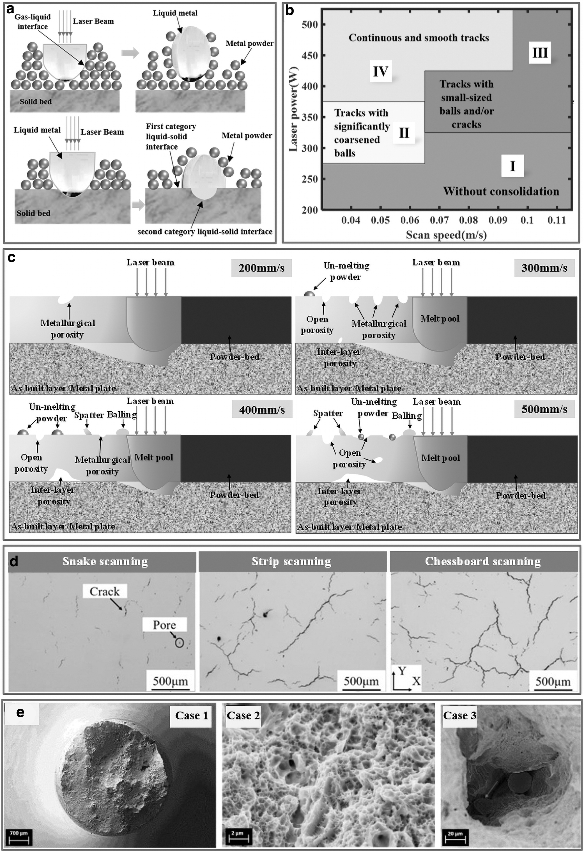
Figure 2a is a schematic diagram of ball formation comparison when the laser does not penetrate the powder layer and penetrate the powder layer. If the laser energy density is enough to penetrate the powder layer to melt a certain solid substrate, the molten pool could be divided into the upper metal powder molten pool and the lower solid substrate melting pool along the upper surface of the solid substrate. In this case, there are three kinds of liquid–solid interface, gas–liquid interface, and liquid–liquid interface on the whole molten pool.
In the first layer of SLM processes, as the surface of the substrate is generally attached with a layer of oxide film, the solid–liquid contact interface is liquid metal/oxide film, which belongs to heterogeneous material wetting and has very poor wettability. 40 Therefore, the metal liquid adhering to the substrate originally due to gravity may break away from the substrate again under the action of surface tension, and the shape of the upper molten pool tends to change to a spherical shape. Li et al. 41 investigated the balling behavior of SLM of pure nickel powder and stainless steel in detail and proposed that the SLM balling phenomenon includes the 10 μm spherical balls and 500 μm ellipsoidal balls.
Gu and Shen 42 studied the metallurgical mechanism of two kinds of the balling phenomenon during directed metal laser sintering of 316 L stainless steel powder. It is mentioned that some techniques can be applied to decrease the tendency of balling, including decreasing powder layer thickness, increasing laser power, and lowering scan speed, as presented in Figure 2b. High scanning speed and low scanning power result in poor substrate heating. The poor heating causes poor wetting, leading to ball formation. Significantly, the wetting conditions could be improved by the reduction, removal, or prevention of oxides. 43
Li et al. 44 reported that the porosity and balling phenomenon on the magnesium alloy surface is quite serious as the scanning speed is increased, and the energy density decreases. Ng et al. 45 stated that the melting track of SLM pure Mg consists of series of discontinuous particles and are affected by surface tension, preventing the SLM processes from spreading uniformly and leading to the formation of the balling phenomenon.
Porosity is a common defect in AM parts. It is particularly important for the application of AM technique, because it strongly affects the fatigue performance and cracks growth characteristics of the final part. 46 The porosity in SLM processes could be managed by adjusting many parameters such as powder layer thickness, laser power, and scan speed. 47 The formation of porosity is that during the material formation process, the material melts and solidifies very fast, causing the gas in the molten pool to not release in real time, remaining in the cooling member to form pores, and the shape of porosity is relatively regular. 48 In addition, inside the AM workpiece, the powder material itself has pores, especially for the atomized powder material; the preparation process is all within the protection range of argon gas.
When the solidification process proceeds, there is inevitably a trace of argon gas inside the parts. Meanwhile, the powder particles would melt into a small quantity of gas or the powders contain a small amount of gas; once these gases cannot be released in time, porosity phenomena would occur. Another type of porosity defect is keyhole porosity, resulting from the instability of the keyhole or the depression zone. When there is an excessive energy input in the melt pool due to low scanning velocity and high laser power, the temperatures would beyond the boiling point of the material, causing the material evaporation and plasma formation; the resulting melt pool becomes deep, and there is a depression zone of vaporized material with the process entering keyhole mode.32,49
Xia et al. 50 investigated the porosity evaluation during SLM processes and reported a transient mesoscale model with a randomly packed powder-bed by the finite volume method, considering the phase transition, interfacial force, and changes in thermophysical properties. The physical mechanism of porosity evolution was discussed as presented in Figure 2c. Galina et al. 51 studied the correlation between process parameters and porosity formation in TiAl6V4 alloy parts manufactured by SLM. Aboulkhair et al. 52 investigated the random distribution of porosity within the manufactured layer, between adjacent layers, and on the surface of the part.
The results showed that a compromise between different parameters and scanning strategies can be achieved with the density of a part of 99.8%. Cunningham et al. 53 utilized an ultrahigh-speed X-ray imaging detection method to investigate keyhole porosity evolution in titanium alloy while manufacturing. Paulson et al. 49 developed an ML method to investigate the correlations between thermal history and keyhole porosity in the SLM processes and predict the probability of keyhole porosity formation of Ti-6Al-4V powder.
Cracks are typical defects in AM alloys, especially in hard-to-weld superalloys, which can cause severe quality degradation, and even early damage or failure. 54 Regarding the cracking behavior in the SLM process, current research mainly focuses on parameter optimization, composition improvement, the addition of second-phase nanoparticles, and post-treatment. 55 In the SLM processes, a very high-temperature gradient is formed between the SLM layer and the substrate material. Meanwhile, the thermal physical parameters of the substrate and the SLM material are not consistent, which can easily lead to thermal stress. 56 When the combined force presents the state of tensile stress, it may lead to a crack. Cracks would occur as the residual stress exceeds the material limitation. 57
Qiu et al. 58 investigated the defects during SLM processes such as balling and cracking, as the pressured assistance was utilized. There are two reasons for causing cracks, including shear stress in the edge and the shrinkage of the melt between the fully melted area and partially melted area. Peng et al. 59 studied the cracking phenomenon by utilizing three different scanning ways for manufacturing René 104 Nickel-Based Superalloy, including chessboard partition, stripe partition, and snake. Figure 2d indicates that different scanning ways have obvious effects on the residual stress, density, and cracking phenomenon.
Meanwhile, Duan et al. 60 studied the effect of energy density on the cracking behavior of René 104 superalloy and proposed that excessive energy input resulted in high residual stress, which leads to cracks in the SLM parts.
Lack of fusion defects, also called incomplete fusion holes, occurs mainly related to a lack of input energy, resulting in incomplete melting of the powder layer. 62 Lack of fusion defects is generally large in size and irregular in shape. In the SLM process, fast laser scanning leads to high cooling rates and severe thermal gradients, causing complex hydrodynamic fluid flow and affecting crystal orientation and growth, generating a lack of fusion powder particles. 63 The edges of such defects are often relatively sharp, easy to cause stress concentration phenomenon, and the tip is often affected by the thermal cycle in the subsequent manufacturing process to induce cracks, thus reducing the fatigue life of parts. 64
Lack of fusion defects is difficult to be solved by the HIP method, and it should be avoided as far as possible in manufacturing processes. Usually, the main causes of lack of fusion defects include too low heat source power, too fast scanning speed, too much material supply, abnormal defocus, and too much scanning spacing. 65
Everton et al. 66 indicated that lack of fusion defects and material discontinuity are the major defects, and their limited control and detection is a key obstacle to the implementation of AM technology. Casati et al. 67 reported the failure mechanisms and mechanical response with different defect distribution, whereas the texture and microstructure of 316 L Austenitic stainless were manufactured along two different orientations. As presented in Figure 2e, a partial lack of fusion powder particles is found inside the layer holes. Meanwhile, Claire et al. 68 proposed a finite element model (FEM) of the SLM processes, which also conducted a numerical validation with the experimental data.
Influence on mechanical properties
Fatigue properties
In aerospace and medical applications, the fatigue behavior of materials is an important part of material selection and part design. 72 Although tensile and toughness data are relatively easy to characterize, the measurement of fatigue data can be a lengthy and burdensome task. To utilize AM technology to manufacture parts, the material properties under fatigue load must be quantified and repeatable. Brandl et al. 73 used computed tomography (CT) to identify material defects and used linear elastic fracture mechanics software to simulate the effect of these defects on the fatigue life of AM parts. These results indicate that the fracture mechanics method can be used to evaluate the properties of AM metals and alloys, and it is instructive to quantify and evaluate the material properties of AM parts.
Xu et al. 74 investigated the temperature fatigue and tensile properties of the SLM manufactured K536 alloy. Three crack initiation sites are found by the fatigue fracture surface analysis. The fatigue stress and fatigue life curves of X and Z orientation parts at 400°C were compared. As the maximum stress increases, the fatigue life decreases significantly. Under the same maximum stress, the fatigue life in the Z-direction is shorter than the fatigue life in the X-direction. Tong et al. 75 summarized the yield strength, fracture toughness, fatigue, and tensile strength of Ti-6Al-4V manufactured by SLM processes.
We have noticed that surface finish is an important issue. When the part was manufactured in a rod or cylindrical shape and processed into a shape, the fatigue strength would increase significantly compared with the part manufactured directly from the fabricated surface. In addition, HIP can usually improve the fatigue performance by closing the subsurface porosity, which may be the fatigue initiation factor, or by providing heat treatment to change the microstructure into a more crack-resistant structure, or a combination of the two factors. Porosity and lack of fusion can cause fatigue and affect the average fatigue life and the variability of fatigue data.
Smith et al. 76 studied the fatigued crack initiation, fatigue life, tensile properties, and fatigue crack growth rate of 304 L austenitic stainless steel. A large lack of fusion defects would significantly reduce the ultimate tensile strength and ductility, reduce fatigue life, and accelerate the generation of fatigue cracks. In contrast, small spherical defects with a diameter of <100 μm have less influence on fatigue and tensile properties. Compared with other properties, the influence of defects on the fatigue crack growth rate is smaller, and it is only manifested in the lack of local acceleration near the fusion defect.
Tensile properties
As mentioned earlier, due to the high cooling rate and fast melting and solidification speed of metal powder during the SLM process, the manufactured parts have finer grain structure and better tensile properties than traditional forged parts. Rafi et al. 77 investigated and compared the fracture, fatigue, and tensile properties of SLM processed Ti-6Al-4V and 15-5 PH steel parts. Compared with the vertically constructed specimens, the horizontally constructed specimens had better tensile properties. The tensile behavior of the PH samples processed in the horizontal and vertical directions was similar to that observed in the case of Ti 64.
Li et al. 78 reported the tensile and microstructural properties of multiple lasers forming AlSi10Mg isolation and overlapping regions. A small quantity of smooth surface appeared on the fracture surface in the overlapping area of two scans, the dimples decreased, and the microstructure became larger, which led to the decrease of tensile properties. Table 2 depicts the tensile properties of the samples. Wu et al. 79 studied the influence of molten pool size on mechanical properties and used multiple sets of molten pool sizes ranging from 7 to 22 mm. As the size of the molten pool increased, its macrostructure changed from columnar crystals to equiaxed crystals, and then into large columnar crystals, which was mainly caused by different cooling rates and temperature gradients.
Tensile Properties of AlSi10Mg Samples 78
However, as the size of the molten pool increased, the tensile properties of the parts tend to decline. Geng et al. 80 took the 5A06 aluminum alloy, for example, to investigate the feature of microstructure, geometric configuration, and tensile properties. When the layer width was 7.2 mm, the minimum angle and radius of curvature that can be manufactured with the wire and arc AM were 20° and 10 mm, respectively. It presented isotropy when loaded in the building direction and vertical direction.
Different In Situ Defect Detection and Monitoring Methodologies
As discussed earlier, in situ defect detection and monitoring are essential for determining the stability and quality of the manufacturing processes during the layer-by-layer production of the parts. Many in situ defects detection and monitoring methodologies for SLM processes have been explored in various fields, including the nuclear industry, aerospace, machinery manufacturing, and petrochemical. 81 The mainstream monitoring and in situ data collection methods include visual and thermographic monitoring.
Meanwhile, some advanced in situ defect detection and monitoring methodologies of SLM technology have also been investigated. And the monitoring system can be conveniently integrated into the manufacturing equipment of SLM processes. Based on the sensor types, the usual monitoring categories include the high-speed camera, infrared Thermography, photodiodes and pyrometer, inline coherent imaging (ICI), X-ray micrography, and acoustic techniques, as presented in Table 3. These monitoring methodologies can significantly acquire the necessary defects and process data of SLM parts.
Literature on In Situ Monitoring and Defect Detection Methods
3D, three-dimensional; CCD/CMOS, charge couple device/complementary metal-oxide semiconductor; ICI, inline coherent imaging; OCT, optical coherence tomography.
Further, these monitoring systems can also be integrated into the feedback control system of the SLM processes to reduce defects in the final part. Table 4 summarizes the advantages and disadvantages of different monitoring methods, and Table 5 presents the mapping of the Literature on monitoring and the main setup parameters and settings of SLM processes.
Summary of Advantages and Disadvantages of Different Monitoring Methods in Selective Laser Melting Processes
CT, computed tomography.
Mapping of the Literature on Monitoring and the Main Setup Parameters and Settings of Selective Laser Melting Processes
Photodiode and pyrometer for monitoring
Presently, many methods inclusive of an electrical, acoustic, visual, and optical imaging method for in situ monitoring and defects detection have been investigated. The optical imaging method has to receive continuous attention because of the benefits of non-contact measurement. The imaging sensors are generally divided into point sensors and distributed sensors. Infrared thermography imaging and cameras with high imaging frame rates are effective but expensive. The photodiodes can effectively measure molten pool behavior in the SLM processes by transforming optical radiation into voltage signals. 82
In addition, the results of the research showed that low-cost industrial-scale sensors can replace high-cost, complex-structured sensors by utilizing multivariate ML and statistic methods. 83 The SLM processes are fundamentally thermal evolution processes. Any changes in input heat parameters would lead to direct changes in the thermal radiation. Therefore, utilizing industrial-scale sensors such as photodiode and pyrometer to measure the radiation situation is an appropriate method for monitoring the SLM processes. 84
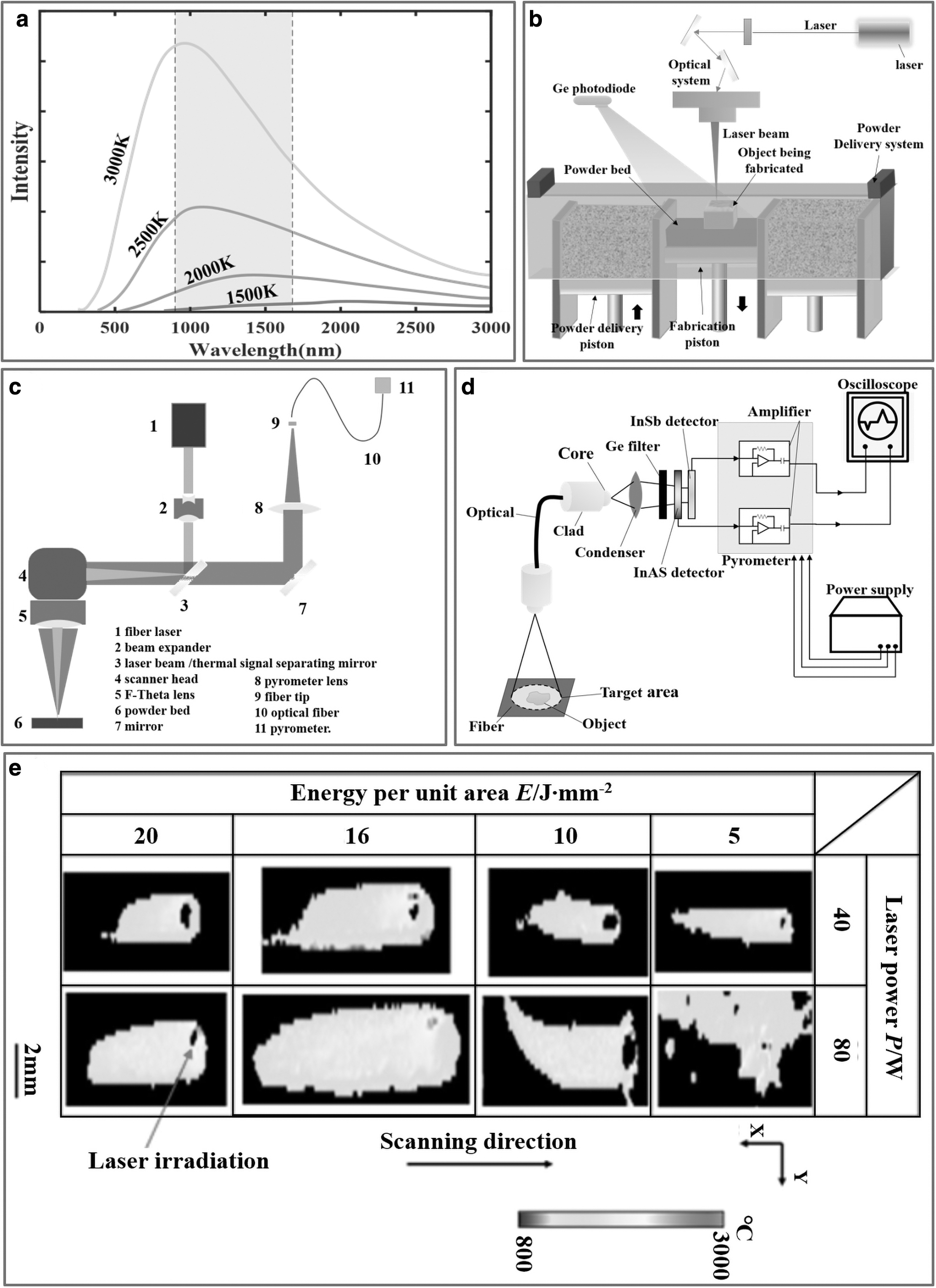
According to the blackbody radiation theory, the spectral existence of radiation emitted by a blackbody at temperature T (K) can be calculated by Planck's law:
As the lack of fusion defects have serious influences on part quality and is hard to detect post-build, Coeck et al. 85 investigated a novel method for predicting the location and presence of lack of fusion defects. The results indicated that the detected signals have a compact relationship with the lack of fusion defects, and the prediction sensitivity is 90%. Fernandez et al. 86 investigated the relationship between thermal emission data in the SLM processes with the surface roughness of the processed parts. The thermal signature of the contour was detected by a photodiodes system.
The results indicated that an on-axis photodiode can be applied to effectively evaluate parts quality because of the connection between thermal emission and surface roughness. Nadipalli et al. 87 reported the setup of coaxial and off-axis sensors installed on an SLM system and tested some single-track samples with different power levels, duty cycles, and scanning speed. Bisht et al. 88 first reported a novel molten pool monitoring tool for SLM processes named DMP-melt pool that utilize a Germanium (Ge) photodiode for monitoring the molten pool and a manual data analysis method for analyzing the quality of parts.
As shown in Figure 3b, the Ge photodiode was mounted in a fixed position covering the whole build plate, and its detection wavelength ranges from 1150 to 1800 nm. The results indicated that the DMP-melt pool tool can effectively predict the quality of AM parts by detecting changing signals and marking them as defects.
However, though low-cost photodiodes can detect optical emission during SLM, the emissivity of the radiation source is not a physical constant and cannot effectively reflect temperature changes. 84 Pyrometers are also known as photo detectors and the temperature measurement by it is rather effective and promising for in situ monitoring and defects detection in the SLM processes, improving the control in manufacturing processes. 89 Implementations of pyrometers include silicon detectors sensing visible light from 400 to 800 nm, Ge photodiodes sensing from 400 to 1700 nm, 90 and indium gallium arsenide photodiodes sensing from 1000 to 1600 nm. 91
Pyrometers are usually applied in coaxial molten pool melting as they have rapid response and convenient installation, making the pyrometers effective to monitor the thermal zone. 92 The pyrometer signals depend on process parameters such as scanning speed, powder thickness, and hatch distance. 93 The relationships between porosity defects and pyrometer signals were first investigated in Berumen et al. 94 In the SLM processes, the process parameters utilized to process various parts are kept constant and the closed-loop controls are missing.
However, there are immediate changes in the molten pool temperature as the part geometry may lead to varying heat flow to solidified sections and neighboring powder or the fumes cause deviation in the manufacturing atmosphere. 95 Therefore, it is significant to measure the molten pool temperature and control the processes with a closed-loop system.
Alberts et al. 96 utilized the pyrometer method to realize laser power and molten pool monitoring, which achieved a measuring time of 10 μs and a closed-loop controlling time of 60 μs. Renken et al. 95 reported a method that ensures fast control of the molten pool temperature in combination with a feedforward method and a closed-loop control strategy. Pavlov and Doubenskaia 97 investigated the temperature radiation of the laser impact zone in the SLM processes by bi-color pyrometer, and the influences of fabrication strategy, hatch distance, and powder layer thickness on thermal variation were also explored. Figure 3c depictsthe schematic of the pyrometer optical monitoring system.
The results indicated that when the thickness of the powder layer is 50 μm, the pyrometer signal increases with the change of the hatch distance; however, when the powder layer thickness is 1 mm, the pyrometer signal decreases with the change of the hatch distance.
Furumote et al. 98 reported the surface temperature measurement of metal powder during the laser consolidation processes by a two-color pyrometer installed as presented in Figure 3d. The results showed that the consolidation structure shrunk in the cooling processes, and the shrinkage appeared when the surface temperature was low enough. Yamamoto et al. 99 investigated melting and solidification behavior, and they evaluated the energy balance and solidified materials in the SLM processes by measuring temperature with the two-color pyrometer.
Figure 3e depicts the color map of the temperature distribution around the laser acting area when the laser scans the 50th path. The results illustrated that the thermal distribution around the heat irradiation zone was asymmetrical, and the thermal gradient on the solidified side of the material was smoother than that on the powder side. Rezaeifar and Elbestawi 100 proposed that three controllers consist of adaptive proportional, simple proportional, and sliding mode for controlling the molten pool temperature in the direction for Inconel 625 superalloy.
Infrared thermography for monitoring
During the SLM processes, the rapid solid–liquid–solid transformation leads to a large temperature gradient, easily causing defects such as cracks and porosity of the metal parts, and reducing the part quality. 101 Liquid/powder spatters and plumes are common thermal behaviors regarding stress evolution, liquid metal convection, and microstructure transformation. 102 As they are important factors for getting better quality parts, monitoring the dynamic thermal behaviors of the molten pool in the SLM processes is quite significant.
The infrared thermography imaging method can effectively record the temperature distribution and monitor the transient thermal response of the SLM processes in comparison with the visible cameras mentioned earlier.
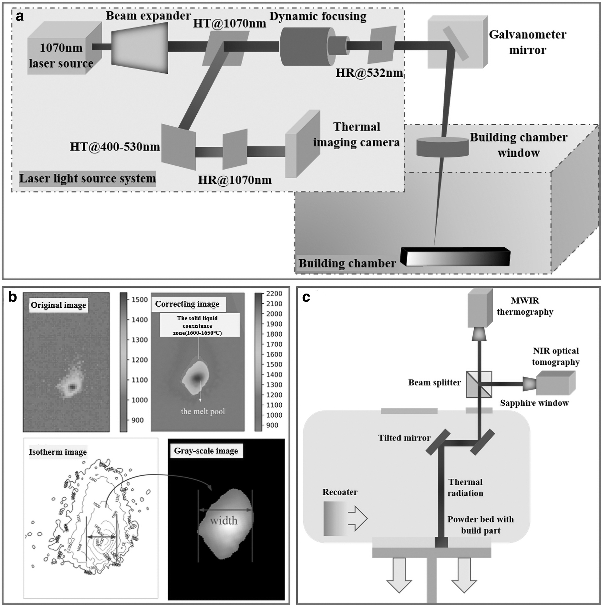
Zheng et al. 103 utilized a LumaSense MCS640 thermal imaging camera to monitor the surface temperature distribution during Ti-6Al-4V processing in real time, and the experimental setup is shown in Figure 4a. The results showed that the prediction of molten pool width can be achieved by extracting the boundary of the molten pool in the infrared images. As presented in Figure 4b. Shrestha and Cheng 104 respectively utilized Heigel's methodology to determine the molten pool boundary and acquire the radiant temperature distribution of the molten areas of the Ti-6Al-4V alloy and Inconel 718 materials by analyzing the captured infrared images.
Krauss et al. 105 investigated the process errors that occur because of insufficient heat dissipation, as well as detected porosity and other irregularities by analyzing the thermal distribution. Ye et al. 106 investigated the plume and spatter signature variation with changing laser power and scanning speed by utilizing a near-infrared (NIR) camera. The results indicated that laser power plays a more decisive role than scanning speed.
In the SLM processes, a 3D thermal field especially cannot be detected by a thermal camera in the depth direction, in terms of this issue. Arisoy et al. 107 reported a simulation model of single-track and multi-track laser manufacturing, scanning speed, laser power, and other process parameters based on different energy density levels by utilization of the 3D finite element method. Mohr et al. 108 proposed an effective and promising examination method for data analysis and identified the relevance of measured signals to process defects. As presented in Figure 4c, two cameras were utilized simultaneously. The feasibility of the proposed monitoring system was verified by comparing it with the measured data from micro-CT.
Moreover, the lack of fusion defects that are larger than 100 μm is the most detrimental. When compared with high frame rate infrared imaging and defects detection methods, full-field monitoring of SLM processes only need lesser data storage capabilities and lower imaging frame rates, facilitating more calculating capabilities for real-time analysis. Bartlett et al. 109 reported and demonstrated a novel in situ monitoring system utilizing full-field infrared thermography to detect AlSi10Mg parts in the SLM processes. The results showed that 82% of the lack of fusion defects could be effectively detected by infrared thermography imaging.
Though various methods have been proposed to achieve in situ monitoring and defects detection in the SLM processes, there is a lack of statistical methodologies to automatically monitor manufacturing processes and detect various defects, as well as signal an alarm during the layer-by-layer processing. Grasso et al. 110 investigated the monitoring methods for difficult-to-process materials such as zinc and its alloy, as they have low boiling and melting points. They proposed a novel in situ monitoring methodology that integrates infrared thermography imaging with a feature extraction approach, and the automated alarm rules were demonstrated.
Charge couple device/complementary metal-oxide semiconductor camera for monitoring
There are some drawbacks such as porosity, cracking, and inhomogeneity in the SLM processes because of operating with limited monitoring and open-loop control. Appropriate in situ process monitoring and defect detection methods allow one to effectively control the stability and quality of the SLM processes. Geometric signatures are the main concerns in the in situ monitoring technologies among all the process signatures of the SLM processes. Some studies utilized monocular cameras to achieve two-dimensional geometric measurement and defects detection, 112 whereas others investigated the verification of the deposited powder 113 and the categorization of the potential error sources. 114
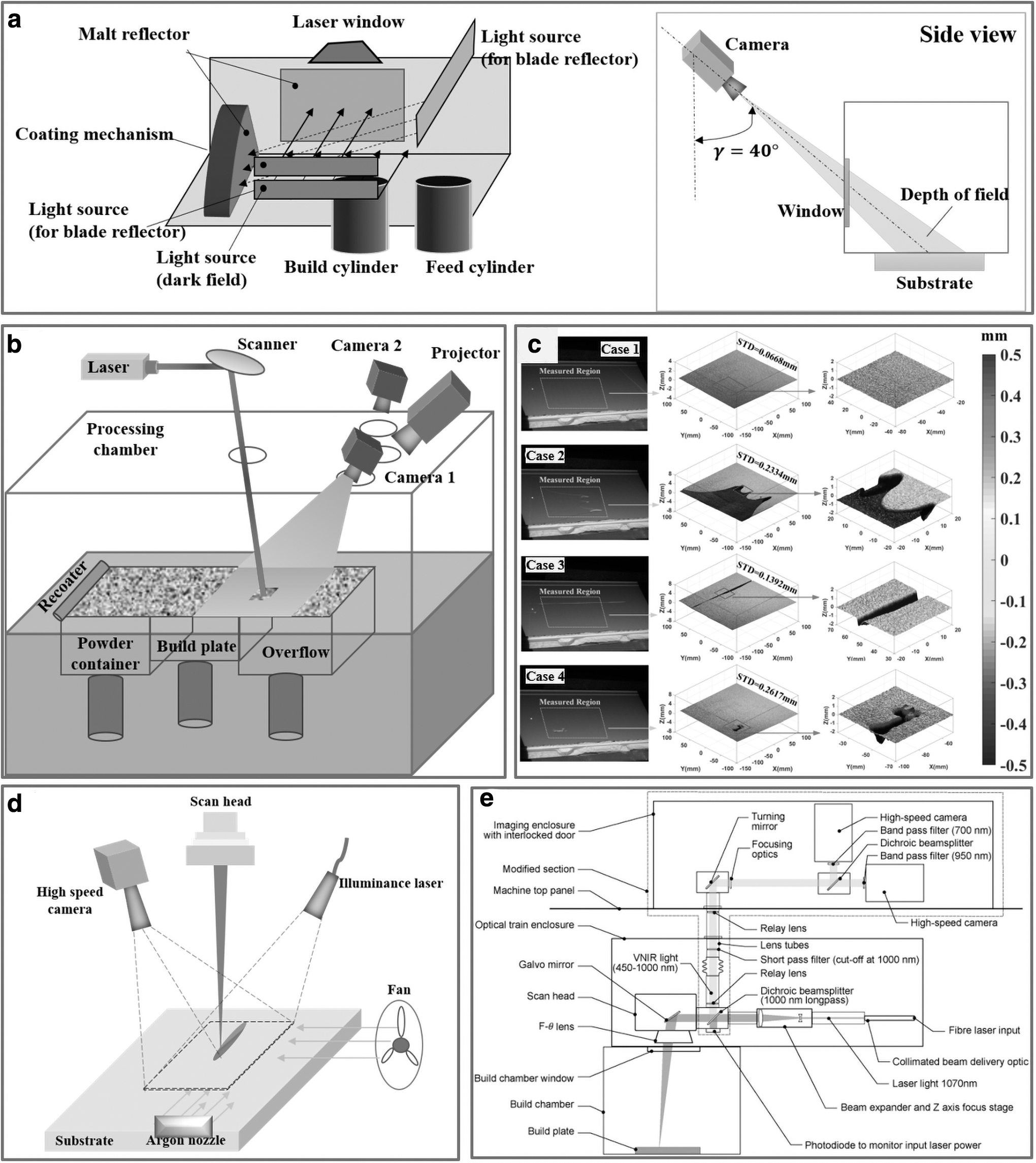
Joschka et al. 115 reported a high-resolution monitoring system for defects detection, as presented in Figure 5a. The results showed that the proposed high-resolution monitoring system can acquire high-resolution images with 25 μm/pixel to 35 μm/pixel of the deposited powder layer, and it can significantly detect topological flaws and surface quality of the built layer. Grasso et al. 116 investigated a methodology for the spatial identification and detection of defects by utilizing a visible camera in the layerwise processes.
A statistical descriptor based on principal component analysis was utilized to identify the defective area. Further, automated defect detection technology has been achieved with the image k-means clustering analysis. Caltanissetta et al. 117 reported for the first time the use of a measurement system to characterize the accuracy of in situ contour recognition in SLM-layered images. The results illustrated that higher measurement repeatability could be obtained by combining appropriate image segmentation and processing algorithms. However, as the in-site monitoring of 3D geometric features was restricted by the harsh measurement environment, most of them were two-dimensional images, and quantitative 3D data cannot be obtained.
Land et al. 118 investigated a novel non-contact metrology system that combines traditional machine vision with a phase-shifting fringe projection system. The results showed that a noise floor of ∼18 μm was achieved. The measurements can produce a high-density 3D point cloud of the final part. Zhang et al. 119 demonstrated the feasibility of measuring the surface topography of powder layers in the SLM processes by digital fringe projection technology. The results showed that the proposed monitoring system can measure powder bed signatures such as surface texture, characteristic length scales on the surface, and powder layer flatness.
However, it was difficult to measure accurate 3D contour data at the slice level because of the limitation of the monocular fringe projection system. Li et al. 120 reported a nondestructive in situ 3D measurement method for monitoring 3D surface topography and 3D contour data in the SLM processes. Figure 5b depicts the proposed in situ 3D monitoring system. An enhanced phase measurement profilometry to improve the accuracy and efficiency of 3D surface topography monitoring was proposed. The 3D full-site table data can be acquired by processing the raster images recorded by the powder bed. Figure 5c depicts the defects of the powder deposition and the measured 3D data of the powder bed. The results indicated that this method can reveal irregularities caused by various defects, as well as detect the contour accuracy and surface quality.
High-speed camera for monitoring
Presently, various monitoring technologies have been applied to detect process radiation molten pool behaviors in SLM processes. For example, it is proven that spatters and plumes can significantly provide data for understanding SLM processes and monitoring manufacturing behaviors. 121 Thus, as melt pool behaviors providing abundant information on process stability, local defects, and microstructure characteristics monitoring, it has attracted the most attention. 122
Zhang et al. 123 proposed an off-axis vision monitoring methodology utilizing a high-speed camera, and a novel imaging processing method for extracting features from the plume, melt pool, and spatters, which is proven successfully extracting spatter area, spatter velocity, spatter number, spatter orientation, melt pool intensity, plume orientation, and plume area. In addition to monitoring temperature, area, length, and width in many types of research regarding molten pools, the depth of the molten pool is also an important index for retrieving a complete set of spatial distribution information. Caprio et al. 124 reported a penetration depth estimation system based on monitoring the surface oscillations of the molten pool.
As shown in Figure 5d, the oscillation frequencies regarding cross-sectional area and effective molten pool penetration depth were all extracted from the high-speed image acquisition after image processing and signal analysis. As all these cameras are installed on the commercial AM machines, they are only available to monitor with a fixed field. Scime et al. 125 reported a coordinate transform method, effectively converting captured images into a more useful format. The transformations require only 0.1 s per frame to conduct; thus, this method can be utilized for the qualitative evaluation of the molten pool dynamics, and it can also be used for the analysis of the post-treatment of the molten pool.
Zhang et al. 126 illustrated a vision system for extracting the features of the plume, melt pool, and spatters based on the process understanding. Lane et al. 127 proposed a method to calibrate and characterize the spatial resolution of a coaxial camera system (LumaSense MCS640 thermal imaging camera) for analyzing the molten pool dimensions, temperature gradient, and cooling rates. As in situ measurements of the molten pool, geometry is difficult to carry out in the AM production environment; a novel, fast, and economically feasible virtual sensing method for estimating molten pool width and depth is reported by Goossens and Van Hooreweder. 128
The molten pool width is determined by a high-speed coaxial monitoring system, and the depth-to-width ratio is calculated from the material properties and processing conditions by a proposed physical-based analytical model. Once the earlier mentioned two kinds of results have been obtained, they would be combined to accurately estimate the molten pool depth. Yang et al. 129 investigated the molten pool regions for super alloy Inconel 625 manufactured by EOS M270 type SLM. Some phenomena have been detected during the SLM processes, including material spatter, under-melting, and over-melting regarding delamination, layer separation, and localized defects. Clijsters et al. 130 utilized a photodiode and a high-speed NIR thermal complementary metal-oxide semiconductor (CMOS) camera installed coaxially with the manufacturing laser beam and connected to the field-programmable gate array.
Repossini et al. 131 first investigated the applicability of using high-speed imaging, feature extraction, and image segmentation, to detect spatter-related data along the laser scanning path. The results showed that the over-melting and under-melting detection efficiency can be improved significantly by monitoring and analyzing the spatter information. Hooper 133 investigated a method that gives the spatiotemporal resolution that is necessary to measure the molten pool surface temperature by utilizing a high-speed camera installed coaxially, as shown in Figure 5e.
The results indicated that the molten pool becomes less stable as the manufacturing operations close to the parts' edge. The developed method provided a new tool to help optimizing process parameters and scan strategies.
Ultrasonic techniques for monitoring
An ultrasound is an elastic perturbation propagated in the form of waves, and it is subject to secondary effects such as reflection, diffraction, transmission, and dispersion as the acoustic field of the incident wave interacts with discontinuities. 134 Ultrasonic monitoring techniques use high-frequency sound from materials and defects, and the sound can be utilized to analyze material characteristics for finding flaws. 135 Moreover, laser ultrasonic imaging is another nondestructive ultrasonic technology that utilizes laser irradiation to generate thermoelastic ultrasound or ablation ultrasound, and it has proved to be a reliable methodology for detecting defects in many application areas. 136
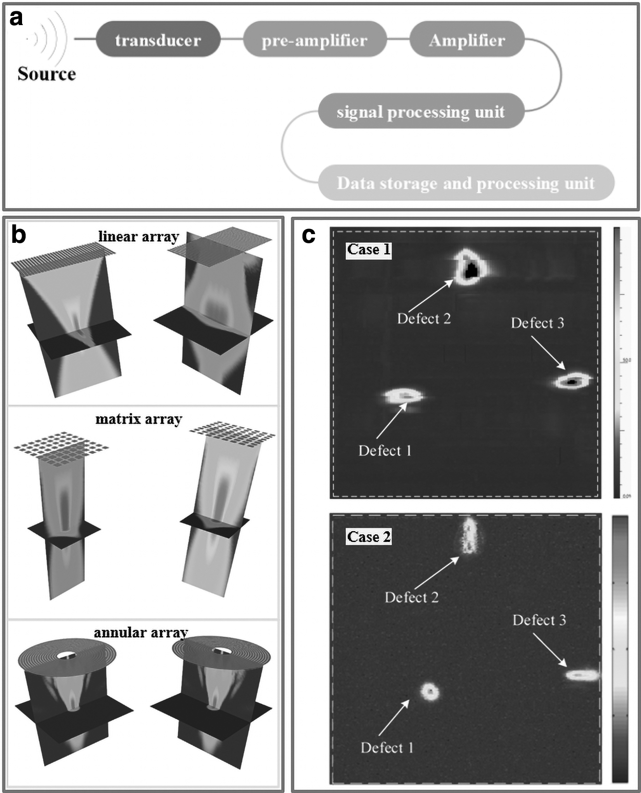
A typical acoustic emission detecting system is presented in Figure 6a. The formation of material discontinuities results in generating acoustic emission signals; thus the elastic wave propagates from the source to the sensor, through the substrate, until it is collected by the acoustic emission sensor. Then, the sensor generates an electrical signal, which is transmitted to the electronic device for further processing and defect detection. 137
Rieder et al. 138 investigated the online measurement by using ultrasound to more accurately understand the complex dynamics of the SLM processes. Through the evaluation of the back-wall signals, the surface dynamics during the surfacing process can be observed, and these signals have an indicative effect on the qualitative evaluation of the residual stress. Eschner et al. 139 evaluated various configurations for process integration of acoustic measurement technology. Different Neuronal Network topologies have been tested, and the accuracy of the best solution has reached more than 90%. Laser-generated ultrasound is quite suitable for the in situ detection of SLM processes. Zhang et al. 141 reported a laser ultrasonic C-scan imaging system for detecting the surface defects of the SLM parts with different surface roughness.
Li et al. 142 investigated the quality detection of TC18 titanium alloy parts by using ultrasonic arrays. As presented in Figure 6b, the 3D acoustic field distribution of different ultrasonic array transducers was established, and the optimal detection scheme was determined. Meanwhile, the total focusing method of the ultrasonic ring array transducer was proposed, and its imaging method was analyzed. Figure 6c shows the comparison of linear array and circular array detection results. The results showed that the total focusing method of the annular array has higher accuracy in quantifying the defects of transverse holes and flat bottom holes with a diameter of 0.8 mm.
X-ray computed tomography for monitoring
X-ray computed tomography (XCT) is a nondestructive volumetric imaging technology that can be utilized to measure the external and internal morphology of parts, as well as acquire 3D information with spatial resolutions of a few micrometers. 143 XCT scans a sample with a cone-shaped X-ray beam generated by high-energy electrons to obtain a magnified projection image behind the sample, as shown in Figure 7a. The intensity of the X-ray beam would be reduced, as it can be absorbed when passing through the samples.
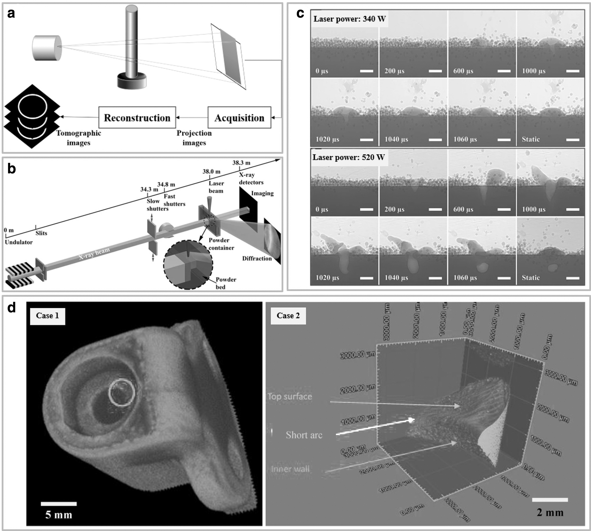
Then, the X-ray detector is utilized to capture many projection images by rotating the sample. All these captured images can be reconstructed into 3D voxel data and each with a different “gray value,” which represents the radiation absorbability of the material. Further, the voxel data would be changed into mesh data or tomographic slice images. 144 The XCT technology has shown promise in verifying the internal geometry of AM parts. 145 The application of XCT technology for measuring surface topography has better prospects as the AM parts commonly feature complex, internal geometries, and the XCT significantly can overcome the access requirement problems that are intrinsic to contact and optical measurement. 146
Cai et al. 147 studied the XCT technology used to characterize the internal structure and improved the understanding of the process parameters of material porosity. The results showed that the porosity can be effectively measured and characterized by size and shape using the XCT method in comparison with the conventional Archimedes method. Pyka et al.148,149 reported the first surface topography measurement using the XCT method, which extracted contours from slice data obtained by XCT measurement of lattice rods. Thompson et al. 146 proven the feasibility of the XCT method for topography measurement of SLM Ti6Al4V parts.
As presented in Figure 7b, the system includes a 160 kV open-tube micro-focus X-ray source with a minimum focal focus variation microscopy and coherence scanning interferometry. The results showed that the XCT part in comparison with technology can obtain a series of information for surface analysis, which helps verify parts with internal or other difficult-to-access surfaces.
Zhao et al. 150 demonstrated that quantitative structural information on powder ejection, phase transformation, molten pool shape or size, and powder solidification can be acquired by using XCT imaging and diffraction. As presented in Figure 7c, the laser power was increased to 520W and irradiated for 1 ms. The image shows that the interaction between laser and metal was much stronger than in the previous case. The Ti-6Al-4V powder and the matrix locally melt quickly. Continuous laser heating makes the melting cavity deep and has strong oscillation behavior.
The molten metal diffuses outward from the surface, and part of it is ejected. Yusuf et al. 152 investigated the microhardness and porosity of the SLM 316 L stainless steel parts by using XCT and Archimedes methods. As shown in Figure 7d, after using advanced XCT to perform a low-resolution initial scan of a relatively complex SLM part, a small area near the internal contour of the part had the highest porosity in comparison with other areas of the entire part.
Maskery et al. 153 utilized the XCT method, microscopy, and hardness measurements to investigate the SLM AlSi10Mg parts, and they demonstrated the applicability of XCT measurement and quantitative defect analysis for SLM process monitoring and improvement. Zhou et al. 154 explored a particle shape characterization method using XCT technology to obtain voxel data of metal powder. The erosion algorithm and watershed algorithm were proposed for particle separation.
Other in situ monitoring cases
Optical coherence tomography (OCT) is a noncontact imaging technology, which is used in many fields where the material properties of the measured object allow the incident laser to be fully transmitted. 155 The OCT technique allows video-3D representation of the measured structure with axial resolutions <10 μm. 156 As the OCT technology has several advantages such as providing 3D volume images with spatial resolution <10 μm, possessing high scanning speed up to 100 kHz, and is conveniently integrated with the measuring system for in situ analysis, 156 it has been widely applied in oncology, 157 ophthalmology, 158 and cardiology. 159
The OCT technology also has a growing tendency in the manufacturing field such as quantitative touch-screen panel analysis, 160 automobile paint assessment, 161 and identification of glass defects. 162 In the SLM process and defect detection field, although some monitoring methods can detect each layer of the parts, they cannot offer subsurface information about the field; thus, the OCT method can significantly fill this gap. 163
Neef et al. 164 applied the OCT method in metal SLM processes, imaging a single layer of 3 × 3 mm powder and hatched scanned region at a sampling rate of 70 kHz. Philip et al. 165 investigated the layer-to-layer height measurement of SLM 316 L stainless steel by utilizing high-speed spectral-domain OCT, as shown in Figure 8a. The spattered particles regarding numerous defect morphologies created high spots in the powder bed and held many layers on the molten surface.
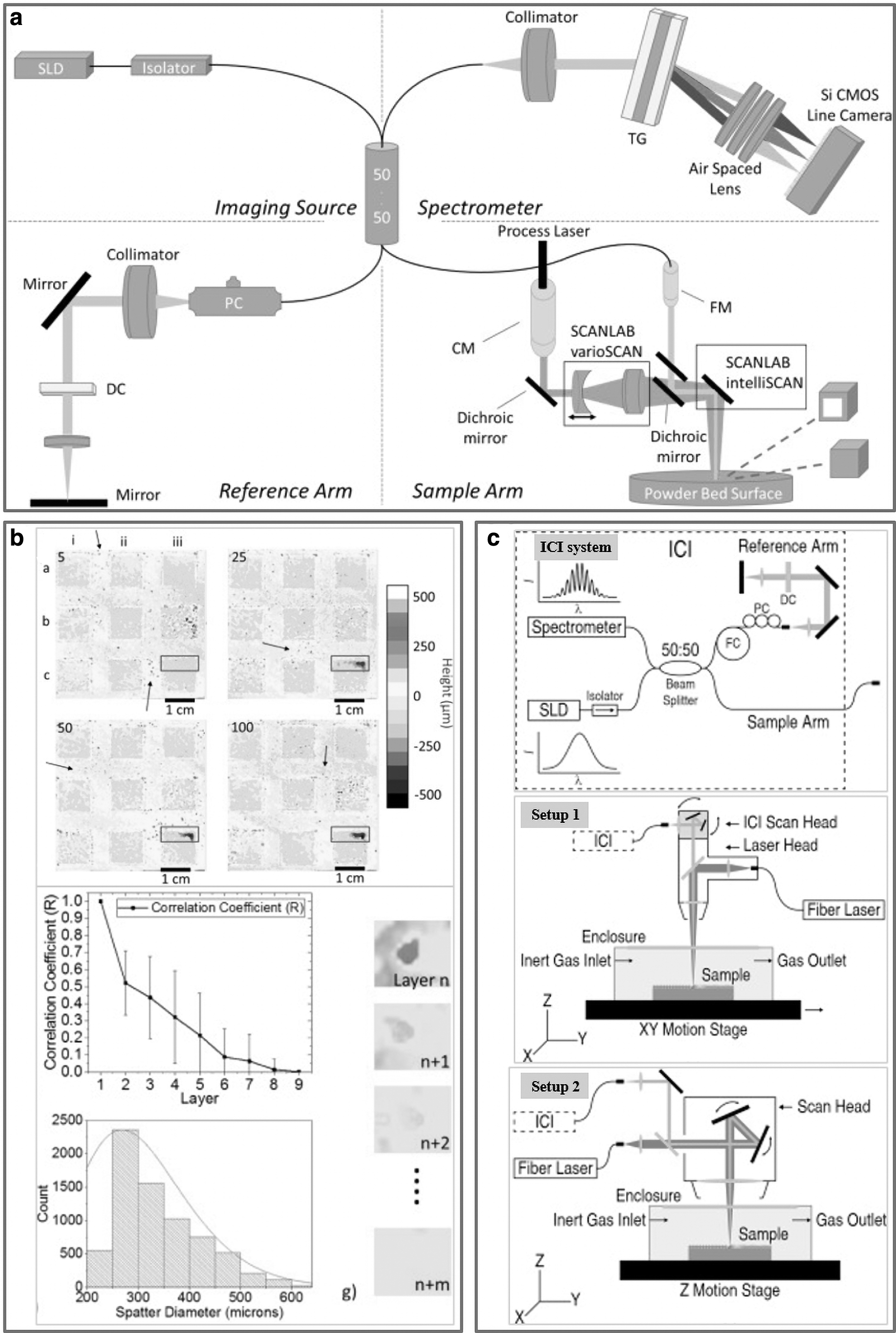
The influences of scan strategy on roughness evolution were investigated by building 100 layers with different scanning speeds and power combinations as well as scanning strategy, as presented in Figure 8b. The results indicated that layer-to-layer scanning rotation was important to minimize the evolution of roughness during the construction process regardless of the scanning strategy.
The ICI is an interferometric technique that utilizes broadband light to measure morphology in the manufacturing processes with micro-scale resolutions. The ICI method captures backscattered intensity as a function of depth and obtains 3D images by raster scanning the imaging beam in XY directions. 166 The ICI method has been applied in some laser processing systems for both feedback control and process monitoring. Blecher et al. 167 have proven the ability of ICI to measure the depth of laser keyhole in several metal materials, including stainless steel, Ti-6Al-4V, stainless steel, DH36 steel, 2219 aluminum alloy, and Inconel 690.
Kanko et al. 112 investigated the monitoring of molten pool morphology changes in the SLM processes by coaxially installing the ICI system stability at 200 kHz, as shown in Figure 8c. The ICI monitoring system was integrated into two different SLM systems (Setup 1 and Setup 2) to study the morphological changes of the molten pool and surrounding areas during a single track under different process conditions. The results showed that the fluctuation of the molten pool has a great influence on the quality of the final trajectory, the process defects caused by poor parameters could be detected, and the characteristic fault characteristics could be effectively identified.
As discussed earlier, a variety of monitoring methodologies that utilize optical, acoustic, and thermal signals have been widely applied, and they can qualitatively establish the relationship between the monitoring signal and the process or defect. However, the accuracy of the monitoring method and the accuracy of the collected signal need to be improved. The quantitative relationship between different physical signals and defects still faces great challenges.
Advanced Research of Defects Detection and Monitoring Technologies
Multiple sensors monitoring technologies
In the SLM monitoring processes, each sensor, as discussed earlier, can significantly measure a certain parameter or phenomenon independently; a series of monitoring systems consisting of several sensors referring to multiple sensor systems has been developed. 168 In the SLM process, the key is to use the built-in sensors of the machine to continuously monitor the process and then detect defects by analyzing the sensor signatures in the flow process in real time; these defects are sealed by subsequent layers to ensure the functional integrity of the SLM components.169,170
Craeghs et al., 171 Tatsuaki et al., 172 and Sebastian et al. 173 investigated the continuous monitoring of molten pools at high speed in the SLM processes to enable real-time feedback control of the process parameters. The in situ monitoring system mainly consists of a CCD/CMOS camera, a photodiode, as well as a data-capturing and -processing system. Aniruddha et al. 174 investigated SLM process data under a wide range of laser velocity settings and laser power by a high-speed video camera and a pyrometer.
Meanwhile, an ML-based predictive model using a single track of quality indicators derived from the height map has also been developed and evaluated. Figure 9a depicts the schematic diagram of two in situ sensors. The average amplitude of the molten pool extracted by the high-speed camera and infrared pyrometer was proportional to the linear energy density. Yakout et al. 176 presented an in situ monitoring system that consists of high-speed infrared thermography and an infrared pyrometer for detecting delamination and spatters of the SLM Invar 36. The installation situation is shown in Figure 9b.
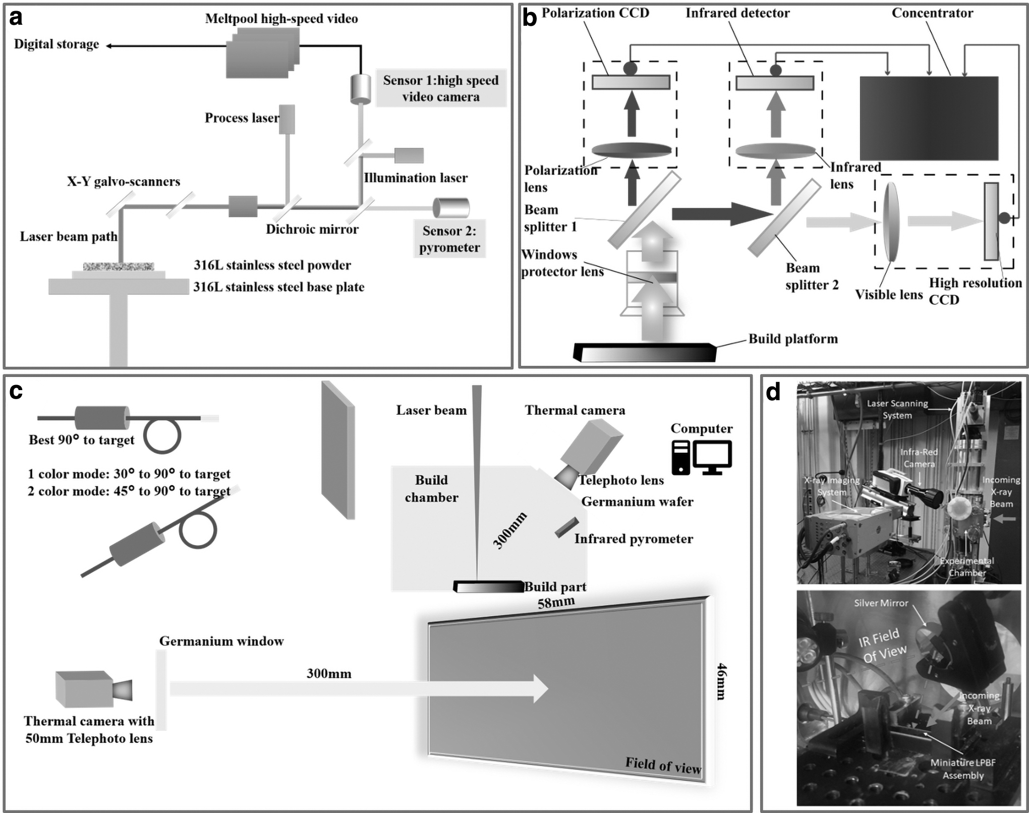
The shape, cooling rate, count, and size of the spatter particles were evaluated. Further, some recommendations for reducing excessive spatter formation and delamination in the Invaar 36 SLM processes were concluded. An in situ monitoring system composed of a high-speed CCD camera, near IR camera, and pyrometer was developed for diagnostics of the SLM processes with different laser power densities. 177 The relationships between the geometric parameters and the laser power density distributions of each track were obtained.
Considering that the SLM processing environment is complex, such as highlight phenomenon, high temperature, and powder pollution may interfere with the monitoring effects, combining the shortcoming of some proposed systems, Peng et al. 178 designed a multi-sensor monitoring system for the SLM processes. As shown in Figure 9c, the multi-sensor monitoring system includes an infrared channel, a visible light channel, and a polarization channel, which can be integrated to detect defects such as balling and porosity in the SLM processes.
Gould et al. 179 reported a new technique that synchronizes high-speed infrared imaging with high-speed X-ray imaging (as shown in Fig. 9d) to study the SLM processes in real time. Observing multiple phenomena at the same time, including vapor plume dynamics, point cooling rates, spatter formation, 3D melt pool visualization, and thermal history, was demonstrated.
The process monitoring based on single acoustic, optical, thermal, and other sensing signals has great limitations. The collected signals are one-sided and the accuracy is low. Based on multi-sensor monitoring of light, sound, heat, and other signals can provide more comprehensive, reliable, and accurate information for real-time monitoring of processing status and identification of defects, and provide the basis for real-time feedback control. Accordingly, it would involve the fusion of multi-type and multi-dimensional sensor signals.
Data fusion of multi-sensor and multi-source signals, maximum mining of information, and judgment of SLM process status and defects is one of the problems that need to be solved in SLM process intelligent monitoring, and it is also the future development trend of SLM process monitoring.
ML technologies
The ML methods have the advantage of learning from given data and automatic decision making,180–182 effectively decreasing human intervention and automatically making predictions in modern manufacturing. 183 The ML algorithm can be classified into the following three categories: supervised learning, unsupervised learning, and reinforcement learning, as shown in Table 6. In supervised ML, the algorithm is trained with labeled data sets. A labeled dataset is one in which the output is known to the input variable. However, in unsupervised learning, the output label of the input training data set is unknown. The algorithm divides the training data set into different clusters according to the relationship between the input data.
Categories of the Machine-Learning Algorithms
CNN, convolutional neural network; PCA, principal component analysis; RNN, recurrent neural networks.
Recently, researchers have made great efforts to monitor defects in the manufacturing process; to detect various processing-related defects such as porosity, cracks, delamination, and lack of fusion; and to optimize the processing parameters. However, as presented in the previous part, all monitoring methods involve many tedious steps and low fidelity. Thus, the ML method provides a novel route for tracking the challenges. 184 In the SLM community, the monitoring methods such as high-speed cameras, infrared cameras, the photodiode, and the pyrometer are the most widely utilized.
The signatures such as spatter and plume, molten pool temperature profiles, as well as different layers of surface images are captured as the inputs layer by layer. Thus, the ML method is obtaining growing popularity in the process monitoring of SLM processes as the monitoring images have high feature dimensions.
Chen et al. 185 reported a supervised ML method for detecting the track defects and predicting the printability of SLM materials. Figure 10a depicts the proposed prediction method. The manufactured tracks consist of five types based on the measured surface characteristics and morphologies. The results showed that the width increased as the speed decreased and the power increased, whereas the height increased first and then decreased as the scan speed decreased. The prediction accuracy of the model was added to be 88.9%, which proved that the prediction method can effectively determine the combination of defect-free process parameters and improve the search efficiency of the parameter window.
Kappes et al. 186 utilized the random forest network (RFN) ML model to study the relationship between the porosity of the manufactured part and the PBF process. Zhang et al. 187 designed a convolutional neural network (CNN) model for learning molten-pool features to predict the porosities attributes in the deposited powder layer. The model can detect porosity with 91.2% accuracy and predict local volume porosity with 1.32% root mean square error. Wu et al. 188 also reported a method combining real-time monitoring and the RFN ML model to predict surface roughness in fused deposition modeling. Baturynska et al. 189 proposed a conceptual framework to optimize process parameters by combining ML with an FEM.
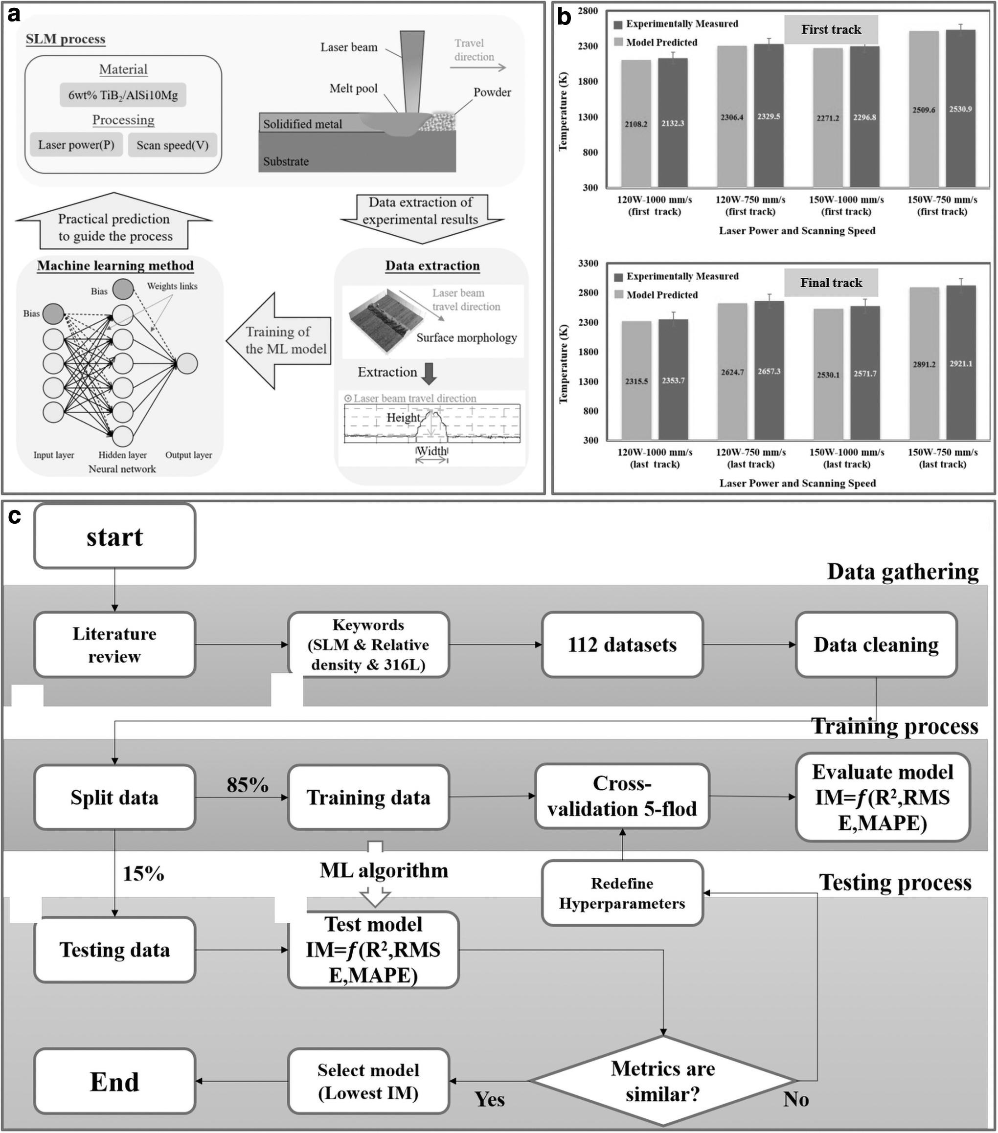
Ansari et al. 190 investigated the 3D finite element analysis utilizing a moving volumetric Gaussian laser heat source for analyzing the molten pool size and the temperature profile in the SLM processes. Figure 10b depicts the comparison of the numerically predicted and experimentally measured peak temperature distribution results. The numerical model is compared with the experimental peak temperature, and the more accurate prediction results are given. The results indicated that the proposed prediction model could effectively predict the molten width with an acceptable error between 2% and 5%, as well as the molten pool depth with an error between 5% and 6%. Currently, the in situ defects detection setups restrict some sensors such as photodiodes and vision applications.
Yadav et al. 191 and Okaro et al. 192 utilized a semi-supervised ML method for inline automatic fault detection and analysis of the acquired in situ monitoring data. They achieved this by successfully classifying “successful” parts with a 77% success rate. Yeung et al. 193 demonstrated a feedforward control method for updating the laser power based on a data-driven predictive melt pool model and minimizing the melt pool variation. The variation of melt pool image area, measured by its standard deviation, was reduced by 78% over the constant power scan strategy (from 0.0181 to 0.0039 mm2).
In the SLM processes, the heat characteristics of the deposited powder have a great influence on the quality of the parts. However, it is quite difficult to accurately determine the melt pool size and large temperature gradient by only in situ monitoring systems and experiments. Barrionuevo et al. 194 proposed a set of ML algorithms to predict the density of 316 L stainless steel 3D manufactured parts and obtain a robust SLM process parameters combination. Figure 10c depicts the schematic diagram of the process of predicting the density of the SLM 316 L parts.
The results showed that the gradient boost regressor has the highest accuracy, followed by the multilayer perceptron and random forest regressor. The algorithms work well for predictions where there is a relative density greater than 97%. Kwon et al. 195 reported a deep neural network for the classification of molten pool images referring to 6 laser power labels. The proposed method showed the classification failure rate under 1.1% for 13200 test images and was more effective to monitor melt pool images. Scime and Beuth 196 utilized computer vision techniques and an unsupervised ML method to achieve in situ detection of balling instabilities and keyholing porosity.
Zhang et al. 197 proposed a hybrid CNN method for PBF process monitoring, which can effectively learn spatiotemporal representation features from the original image. The overall detection accuracy of four process conditions, normal, balling, overheating, and irregularity, can be up to 0.997. Zhang et al. 198 used high-speed cameras to capture images of molten pools, plumes, and spatter. These images are used to train the SVM classifier and CNN to detect process anomalies. Compared with the SVM classifier, the CNN model shows a higher accuracy rate of 92.7%, and the latter shows an accuracy rate of 90.1%.
Baumgartl et al. 199 used CNN to detect defects from thermographic images. The defects such as delamination and splatter can be recognized with an accuracy of 96.80%. However, the model cannot identify other defects, such as balling, lack of fusion, and keyhole.
In the SLM process, machine vision, data acquisition, image processing, data analysis, and feedback control are integrated to realize real-time monitoring, closed-loop feedback control, and defect correction, which is of great significance to quality improvement and flexible manufacturing of SLM components. The ML algorithm has been widely applied in SLM process monitoring. For example, the ML algorithm is utilized to establish the relationship between the signal and the defect or process, to classify or predict the defect or processing state based on the collected signal to extract features.
However, the current monitoring signal processing is mainly after SLM processing, and the laser scanning speed is fast in the SLM process. To realize real-time monitoring and control, the data processing time should be considered. At present, the feedback control strategy based on ML technology is just emerging in the SLM process control scheme, which needs further research.
Future Prospects and Conclusions
This article has reviewed various defects such as balling, porosity, crack, and lack of fusion, as well as their influences on the SLM parts. Several common and advanced in situ monitoring and defect detection methods and their applications are also summarized to improve the quality and stability of SLM processes, including high-speed camera monitoring, infrared thermography thermal monitoring, photodiode, and pyrometer monitoring, multi-sensor monitoring, ML monitoring, and detection methods, and so on.
Presently, the existing in situ monitoring and defects detection technology does not meet the actual use requirements referring to inspectable defect types, inspection accuracy, and efficiency, real-time performance, and robustness. It is expected that the technology would transition from offline principal verification to actual online application, from a single detection principle to multi-principle multi-sensor integration. To ensure the real-time performance of the online monitoring system, it is necessary to quickly analyze a large amount of data obtained by measurement, which requires the joint improvement of software and hardware to accelerate the process of data processing.
Algorithms are the core of control systems and data processing. With the development of big data and artificial intelligence, advanced algorithms can be combined with industrial processes, such as introducing popular neural networks, ML, and deep learning into the AM processes. The online monitoring process makes the entire monitoring and control process more intelligent, which is also the direction of future research on AM process monitoring and defects detection.
Footnotes
Author Disclosure Statement
No competing financial interests exist.
Funding Information
National Key R&D Program of China (No.2017YFA0701200), National Natural Science Foundation of China (Grant No. 52075100), and Shanghai Science and Technology Committee Innovation Grant (Grant No. 19ZR1404600).