
Abstract
The injection molding process is only economical with large batch sizes due to expensive tools that cannot be used variably. Additively manufactured tools made of plastic could reduce manufacturing costs and represent an alternative to conventionally manufactured tools for prototype applications as well as enabling small series with the injection molding process. The aim of this article was to examine additively manufactured injection molding tools; to determine their potential in terms of service life, surface quality, and production time; and to link them with the production costs so that the profitability can be assessed. Therefore, a reference component and an injection mold have been designed. To test the capabilities of different 3D printing techniques and materials, three molds have been produced by fused filament fabrication (FFF), one by PolyJet process, one by digital light processing, and for a direct comparison to conventional methods, one mold has been milled from aluminum. All molds have been tested in two series. First, they were used under the same conditions over a period of 100 injection molding cycles. Based on the knowledge obtained and an additional profitability analysis, three forms could be identified as promising. Two of these forms could be further investigated in a second series of tests. Based on all experiments, the technical feasibility of additively manufactured injection molds for small batch production could be confirmed. It could be evaluated that each manufacturing process and every material has some advantages and disadvantages. On the one hand, temperature-resistant thermoplastics can be processed with FFF, which can withstand service lives of more than 150 cycles without any signs of wear and are therefore suitable for small series. On the other hand, the PolyJet process achieves good surface qualities and short production times, which means that it can be used for prototype applications.
Introduction
The production of plastic components using injection molding has different advantages and disadvantages compared with various additive manufacturing processes. For this reason, an appropriate production process is selected depending on the individual problem. Additive manufacturing is characterized, among other things, by the freedom of design and availability of machines in lower price ranges. Due to the long production times, however, high quantities are currently not economical.1,2 In contrast, the injection molding process can produce large numbers in a short time. However, new tools must be manufactured for new components. This is usually done using machining processes.
Metals such as aluminum and steel are used as materials. The creation of these tools is time consuming and costly. To carry out test runs, prototype tools are required in addition to the tools for production. These provide information about settings on the machine and can identify potential weaknesses in the component. However, this further increases the costs of tool manufacturing.3,4 Since it is usually not possible to do without the prototype tools, alternatives to reduce costs are being researched. Additive manufacturing is an option to produce injection molding tools.
As a result, the desired shapes can be produced in a short time and at reduced costs. The question arises as to whether the quality of the additively produced prototype tools can be compared with the conventionally produced tools from later series production to derive the best possible setting parameters for the machine and component optimization. For additively manufactured forms made of metal, the reservations regarding comparability are considered refuted.2,4 Additively manufactured tools made of plastic are rarely used due to the aforementioned reservations. However, the inexpensive production offers economic potential.
Some aspects of the injection molding tool have an influence on the functionality and economy of the later molded parts. The surface quality of the molded parts is primarily determined by the surface properties of the tool. This can change due to the mechanical and thermal influences of the manufacturing process. In addition, the service life of the tool defines the batch size of the components to be produced and, together with the production time, the profitability of the manufacturing process. Functional and economic aspects of injection molding tools can be controlled by using different materials and processes in the production of molds. 2
The aim of this study is to investigate the potential of additively manufactured plastic injection molding tools regarding the mentioned parameters. The confirmation of the technical feasibility is of great interest for the production of small batch series. Potential fields of application are prototyping parts before mass production or the manufacturing of middle-sized series, where 3D printing is too time-consuming and injection molding with metal tools is too complex and costly. A profitability analysis shows a connection between the technical functionality and the financial expenditure for the generation of the examined tools. Finally, the examined injection molding tools are compared and evaluated. The results serve as the basis for working with additively manufactured plastic injection molds.
With additive manufacturing, three-dimensional geometries are automatically created by connecting volume elements. 2 This is done using different process variants. The methods used in this study include fused filament fabrication (FFF), Polyjet, and digital light processing (DLP).
In the FFF process, a material thread (filament) is rolled up on a spool. This usually consists of thermoplastics. Polylactic acid (PLA) and acrylonitrile butadiene styrene are often used; other materials such as wood, metals, and carbon fiber can also be incorporated. The material thread is fed from the spool into the printhead. The conveyance is realized by a bearing and a feed wheel connected to the motor, between which the material thread is clamped. The partially melted material is pressed through the nozzle by means of heating elements in the print head through continuous conveyance. The extrudate is then applied to the printing plate in thin lines. The parallel movement of the print head to the printing plate creates a layer. The next layer is made possible by moving the print head or the printing plate in the orthogonal direction to the printing plane.
This means that the printhead goes up or the platen goes down. A new layer can then be created by applying further material threads. The component is created by lining up these material layers. The addition of support structures enables overhangs to be created that would otherwise not be manageable. After the component has been manufactured, the support structures can be removed.2,5,6
In the Polyjet process, the print head, which moves in one plane, has different material outlets. First, one or more materials are provided for the formation of the three-dimensional shape of the component. Second, a support material is used to implement support structures. A UV lamp is also attached to the printhead. Model material and support material are applied to the printing plate simultaneously and in layers, smoothed by a roller, and cured directly by the UV lamp. Only complete layers are created that have no areas that were not filled by model material or support material. After a layer has been applied, the printing platform moves down and allows another layer to be built up. When the volume generation has been completed, there is a block made of both materials. The support material is then washed out by special cleaning systems.2,7,8
In the DLP process, a lighting unit is used to solidify liquid material. Projectors are used that illuminate the full cross-section of a layer at the same time. The liquid material is provided in the form of a resin in a tub. Depending on the design, a gap is created either between the liquid surface and the print bed or between the liquid bottom and the print bed.
In the first type, a coating device ensures that the resin is evenly distributed. In the second type, the distribution of the resin is achieved by a negative pressure when the print bed is raised as well as by gravity. The projector illuminates the liquid gap, depending on the design, from above or below with the contour provided for the layer and ensures that it cures. A new gap is created by moving the construction platform, which is filled with resin and then cured by the projector. In this way, different layers are generated that make up the complete component. Support structures are created from the same material as the component and must then be cut off. Since the resin reacts to UV light, a device is necessary to protect the process from external light sources.1,2,9,10
In previous work,11,12 the use of additively manufactured injection molding tools made of plastic was proven. Various materials and processes can be used to successfully produce injection molded parts. Further research presented by Mohamed et al. deals with the analysis of weld lines in a thermoplastic polymer manufactured by injection molding. 13 In their publication scanning, acoustic microscopy is used to detect and evaluate potential defects in components.
Also, Davoudinejad et al. focus on quality aspects. 14 In their research, they investigate the influence of thermal aging on the fracture and lifetime of additively manufactured mold inserts. They designed and produced an injection mold by photopolymerization and simulated the injection molding process by heating and cooling cycles. In series of tests, they analyzed the effects of thermal aging and crack propagation on the quality and dimensional accuracy of the molds. Although those publications demonstrate the technical potentials of additively manufactured injection molds, first attempts to compare the functionality of the additive tools with the cost expenditure were also made. 15 A detailed economic analysis with an evaluation of the examined tools is not yet available.
Materials and Methods
For this study, injection molds are produced using different processes and materials as well as compared with a conventional tool. The examination and evaluation criteria include the production costs, service life, surface quality, and production times of the respective shapes. The investigation takes place in two phases. In the first phase, all molds are used under the same conditions and subjected to injection molding cycles for the same duration. Before and after each series of tests of a mold, it is examined at defined points by using a light microscope. This is intended to identify wear induced by the injection molding process.
On the one hand, this series of tests can be used to determine the potential and weak spots of the processes and materials for the manufacturing of the injection molding tools. On the other hand, the information about the service life of the molds can be used for the subsequent profitability analysis. Based on the information received about the functionality and economic efficiency of the tools, these are compared and evaluated. In the second phase, the knowledge gained from the first phase is implemented in the form of adjustments in the manufacturing process and post-processing of the tools. This enables a final assessment of the potential of the additively manufactured injection molds used.
The properties of components that are created using additive manufacturing depend not only on the process, but also on the machines and materials. Table 1 shows the manufacturing processes, machines, and materials used for this study.
Used Manufacturing Processes, 3D Printers, and Materials
DLP, digital light processing; FFF, fused filament fabrication; PEEK, polyether ether ketone; PET, polyethylene terephthalate; PLA, polylactic acid.
A Babyplast vertical V 6/10 micro injection molding machine is used for the injection molding process. With this machine it is possible to manufacture components in the milligram and millimeter range. In this case, no screw is used in the plasticator; instead, a plasticator with two pistons, one for melting and homogenizing and one for preparing and injecting the plastic, is used. The injection molding process uses polypropylene as a plastic. Since it is the most widely used plastic in the injection molding process, the test series represents practical conditions. 22
The molded parts produced with the injection molding machine represent the counterpart to the additively manufactured negative mold of the tool. Accordingly, the geometry of the molded part to be manufactured has an influence on the injection molding process as well as the additive manufacturing process. Since components with small wall thicknesses are typically used in the injection molding process, the molded part and the mold for this study are designed in such a way that small channels are present and low wall thicknesses are achieved.
To simplify the approach, only one tool half is produced whereas the second tool half is replaced by a flat metal plate attached to the closing side. Care must be taken to equip the component in the demolding plane with a flat base to enable the mold to be closed. Further, the installation space for the tool is limited by the micro injection molding machine to a construction space of 80 mm × 80 mm × 15 mm. Since the injection molding machine must be adapted to each new geometry in the tool, an uncomplicated geometry is designed for the injection mold. The models in Figure 1 result from the formulated objectives for the construction of the molded part and the shape.
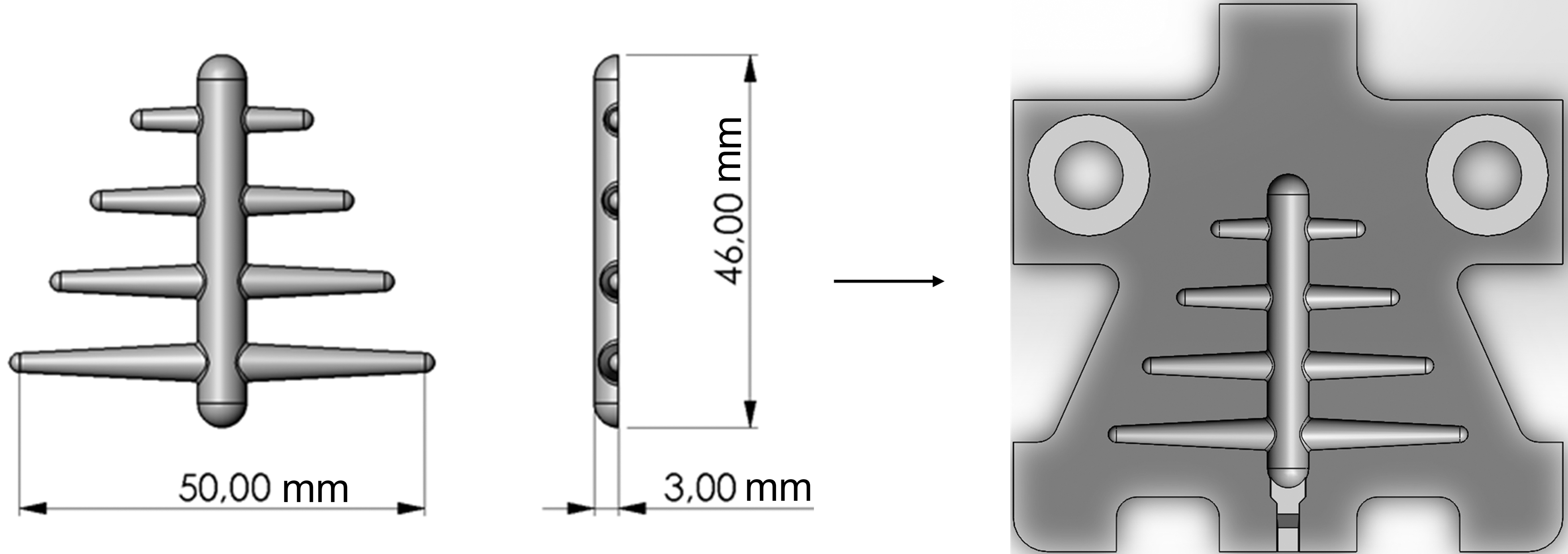
Design of the molded part and the mold as a result of the formulated objectives for the construction.
Figure 2 displays the five additively manufactured molds made of plastic and the milled mold made of aluminum. With the Agilista-3200W and Perfactory P4K 75, the CAD models of the tool shapes are reproduced in the best possible way from all additive manufacturing systems used. This is due to the small layer thicknesses and high resolutions that are possible due to the process. In contrast, the Anycubic Mega X and Apium P155 shapes produced with the FFF process show extruded plastic sheets. Accordingly, these shapes have a rougher surface than the tools produced with the Polyjet and DLP processes. In the molds made from polyether ether ketone (PEEK) and 3dkTOP, manufacturing defects such as loose plastic threads or accumulated material residues can also be seen. The milled metal shape depicts the main cylinder, the conical ribs, and the radii as best as possible.

Display of the five additively manufactured injection molds and the milled injection mold made from aluminum. Color images are available online.
Results
For an overview of the wear, Figure 3 shows microscopic images of 3dkTOP, PEEK, AR-M2, and E-Denstone both before and after 100 parts have been produced with the molds. Due to the fact that the central channel is exposed to temperature and stress the most, only the relevant areas are marked and described in the Nomenclature section. Since no changes are visible in the mold made of aluminum, it is not displayed. In the following sections, the behavior of each material is described in detail.
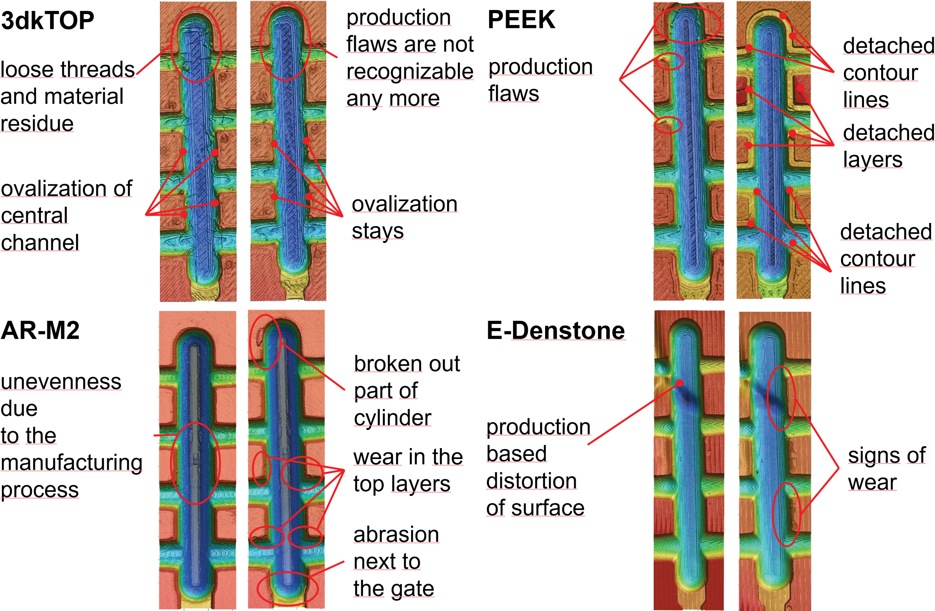
Microscopic images of four injection molds before and after 100 molded pieces. Color images are available online.
3dkTOP
The mold made of 3dkTOP has to be thermally treated before it can be used in the injection molding machine, since the polyethylene terephthalate does not develop sufficient crystal structures during the manufacturing process of the mold, despite the crystallization accelerator, to achieve the desired thermal and mechanical properties. The thermal post-processing leads to a distortion of the shape, which can still be used in the test series. There are no significant signs of wear on the mold over the course of 100 cycles. The test series shows high resistance to demolding, which leads to microcracks in the molded parts due to manual demolding. This results in an undesirable increase in the opacity in these areas.
In addition, no material residues or plastic threads can be seen in the mold as a result of the test series. This means that the surface imperfections have been removed by the molded parts. Such molded parts would be scrap in series production. In addition, the usage of release agents could improve the demolding and reduce the wear of all molds produced by FFF.
Polylactic acid
The PLA mold cannot be demolded after just one injection molding cycle. Forced demolding reveals a hole near the gate that was formed by the high temperature during injection molding. As a result, the PLA mold is irreparably damaged.
Polyether ether ketone
In the case of the PEEK mold, the rough surface also makes the demolding process more difficult. At an early stage of the test series, the contours are then detached from the layers of the form. Since the material PEEK is one of the most thermally and mechanically resistant plastics, a processing error can be assumed here. A sufficient connection between the inner contour and the infill and between the layers is not created during production. This is due to a lack of space heating, as a result of which the glass transition temperature of the extruded polymer falls too early to form sufficiently crystalline phases.
Especially the areas that are produced one after the other (contour–infill, layer–layer) have inadequate crystalline compounds that are responsible for the thermal and mechanical properties. By increasing the temperature in the installation space, the time it takes for the temperature to fall below the glass transition temperature is extended, which results in a higher degree of crystallization. In this way, a more homogeneous structure is created, and the thermal and mechanical properties of the component are improved. 23
AR-M2
Due to the smooth surface of the AR-M2 mold, there is little resistance to demolding. Nevertheless, there is increased resistance to demolding at the upper contour edges of the mold. After ∼50 cycles, a part breaks out of the plastic tool at the tip of the central cylinder when demolding. After the test series, signs of wear can also be seen on the remaining upper contour edges. Also, the use of release agents leads to accelerated damage to the mold. Due to the insufficient information about the chemical composition of the material, it is not possible to assess the occurrences.
E-Denstone
When manufacturing the mold from E-Denstone, complications arise. The component detaches itself repeatedly from the construction platform during the manufacturing process. Due to the negative pressure when lifting the building platform, the layer between the building platform and the exposure unit has to be coated with new resin. Since the shape to be produced is a fully filled cross-section, a high negative pressure occurs, which leads to the detachment of the component. The injection molding tool can be manufactured by tilting the component in relation to the construction platform. This causes the mold to bend slightly so that there is no flat surface in the demolding plane.
The test series can be carried out, but plastic spreads on the surface of the mold, so that the molded parts cannot be produced as intended. In addition, there are strong signs of wear in the lower levels of the mold. These are due to the thermal stress of the injection molding process. Subsequent treatment in a curing box can increase the thermal resistance. The surface of the form is illuminated with UV light in a warm atmosphere. This penetrates the uppermost layers of the component and ensures further cross-linking of monomers that have not yet been cross-linked. On the other hand, post-processing with the curing box can lead to further signs of warpage, which must be prevented by adjusting the production parameters. 9
Aluminum
During the test run with the aluminum mold, there were no problems or signs of wear on the mold. The surface quality of the molded parts is optimal, and the demolding resistance is minimal.
Economic analysis
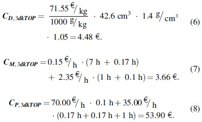
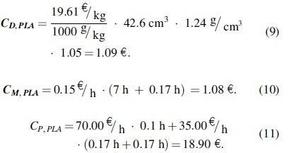
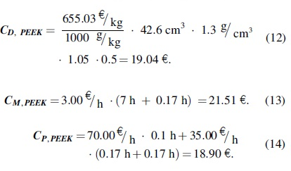
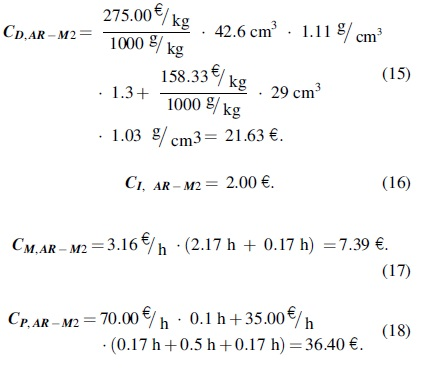
Jacob differentiates between two variants of economic efficiency: on the one hand, the provision of a certain service while minimizing the use of funds; on the other hand, the maximization of the service with a certain use of funds. 24 In the present case, the resources are combined into costs to produce an injection mold. Only the manufacturing costs are considered. After the cost calculation, the results are linked with the service provided, in the form of the service life of the molds. To calculate the manufacturing costs of an additively manufactured component, the procedure is based on Schmidt. 25 Further equations are oriented toward Pahl et al. 26

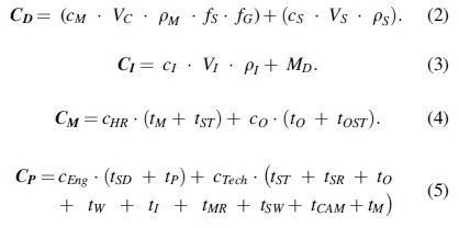
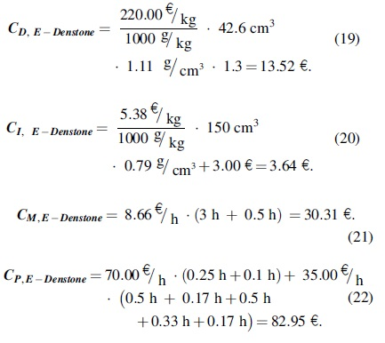
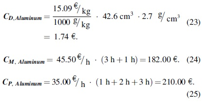
As shown in Equation (1), the total costs are divided into individual cost items, the direct material costs, the indirect material costs, the machine costs, and the personnel costs. The composition of the individual cost items is shown next:
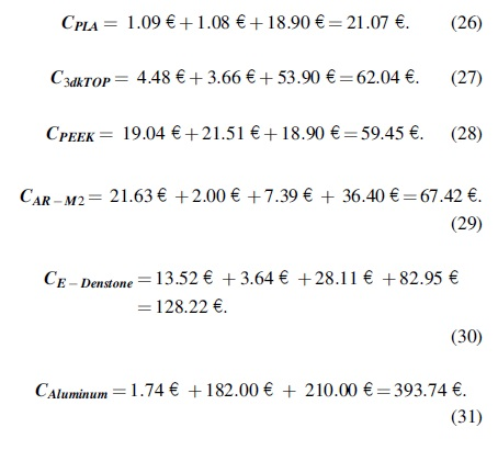
The individual cost positions are calculated for each of the additively manufactured injection molds (Fig. 4).
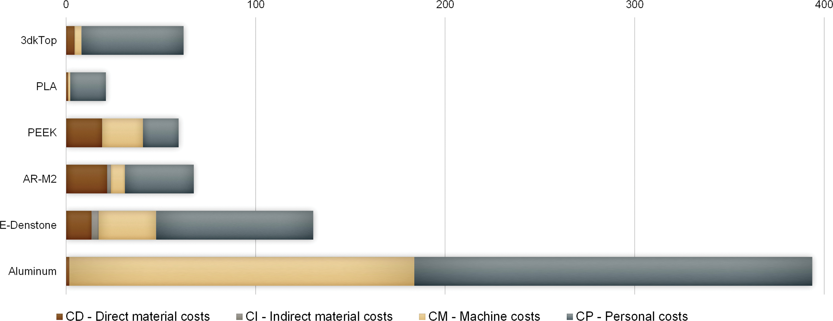
Cost distribution for one injection mold in €. Color images are available online.
3dkTOP
Polylactic acid
Polyether ether ketone
AR-M2
E-Denstone
Aluminum
Total costs
The individual cost positions for each mold are added next to determine the respective manufacturing costs:
Economic efficiency
To determine the economic efficiency of the individual molds, the respective production costs are divided by the corresponding service life. If the service life could not be determined from the test series, these are approximated.
The mold made of the PLA material is destroyed during the injection molding process, so the service life is set to one component per tool. The shape made of the material 3dkTOP warps during the thermal aftertreatment. Signs of wear cannot be seen after 100 injection molding cycles. A significantly longer service life than 100 cycles cannot be assumed, as insufficient information is available for this. The service life is set at 150 components per mold.
The PEEK mold is destroyed at an early stage of the test series due to the lack of layer adhesion. No signs of wear can be detected in the vicinity of the gate. The problems that lead to poor layer adhesion can be prevented by heating the installation space. Due to the high heat resistance and the high melting point, a significantly longer service life than 100 cycles can be expected under optimized conditions. The service life is approximated to 500 components per mold.
In case of the mold made of AR-M2, part of the upper contour edge breaks out at the tip of the central cylinder after 50 injection cycles, what is assumed to be the service life. The mold made of E-Denstone shows the first signs of wear after just 10 injection molding cycles, which become more pronounced as the test progresses. The service life is set to 30 injection molding cycles, from which point no flawless molded parts can be produced.
The service life of aluminum tools for injection molding applications varies greatly depending on the alloy components and the post-processing. With high-strength aluminum alloys, service lives of 30,000 to 250,000 injection molding cycles can be achieved.27,28 In the present case, no high-strength aluminum alloy and no post-processing is used. Accordingly, premature wear is assumed, and the service life is approximated to 10,000 injection molding cycles. In summary, the Equations (32)–(37) display the costs per molded component.

Due to the short service life, the cheapest mold made from PLA is the most inefficient. In addition, the three shapes made from the materials 3dkTOP, PEEK, and AR-M2 clearly differ in their economic efficiency, whereas they have similar manufacturing costs. Due to the 10 times longer service life of the mold made of PEEK compared with AR-M2, the costs per molded part are around 10 times lower, which is synonymous with the highest economic efficiency of all additively manufactured molds.
The tool shape made from 3dkTOP has a service life that is around three times as long as the mold made from the material AR-M2, which means that the additive molds are second most economical. With the highest manufacturing costs and the second-lowest service life of the additive tools, the mold made of E-Denstone ranks between PLA and AR-M2 in terms of its economic efficiency. With its long service life, the aluminum mold compensates for the high production costs, which means that it is three times more economical than the mold made from PEEK.
It should be noted that the profitability also depends on the planned batch size in the individual case. If a prototype tool is produced with which 500 injection molding cycles are to be carried out, the profitability of the aluminum mold in the case described drops to 0.79 € per component. Despite the potentially longer service life after the end of the cycles, there is no use for the mold, and the tool made of PEEK would be more economical. Figure 5 visualizes this aspect. Although on the abscissa the planned quantity is plotted, the ordinate shows the costs per piece in €, leading to a sawtooth pattern due to each reproduction cycle.
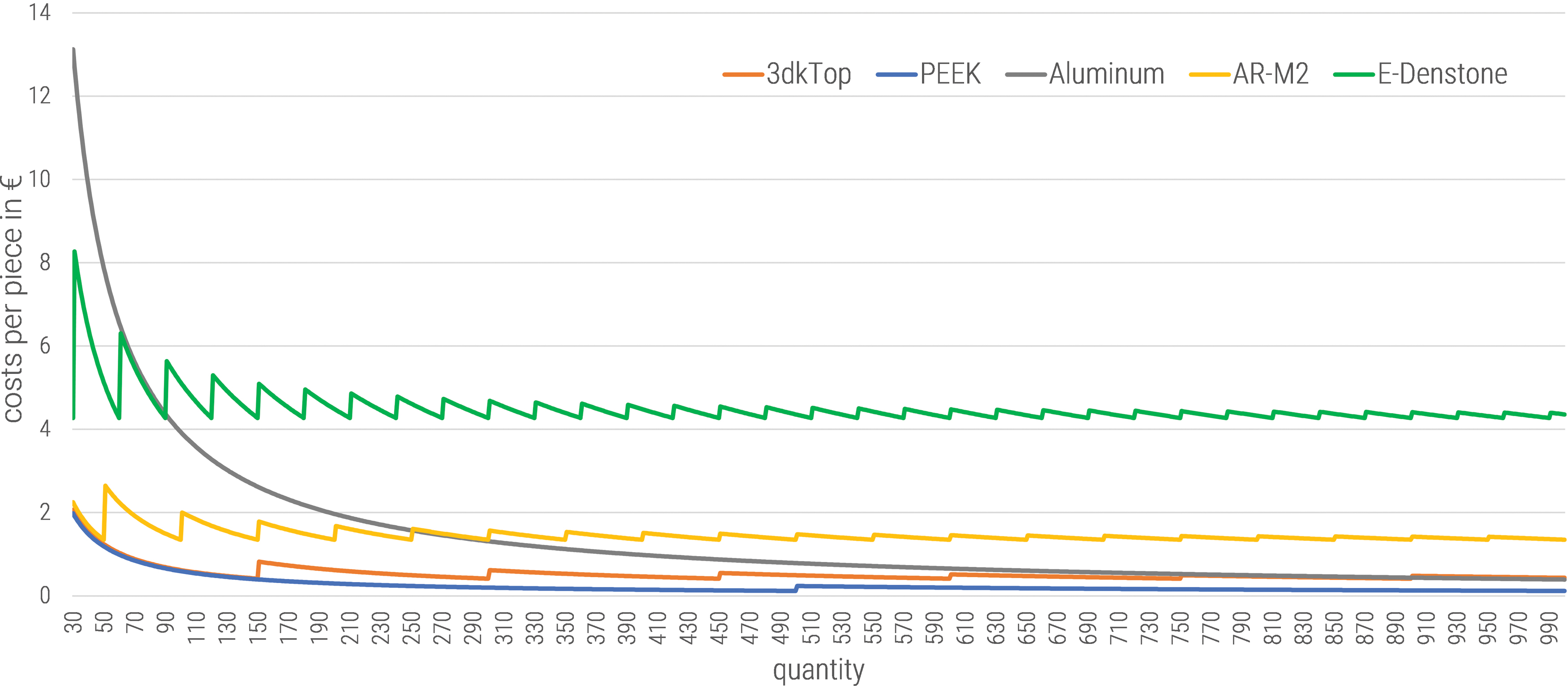
Costs per piece in € from 30 to 1,000. Color images are available online.
Discussion
In the study carried out, different results were achieved with the additively manufactured injection molding tools. Some molds qualify for further investigations; others generate inadequate results and should not be considered further in the future. The lack of thermal resistance leads to early failure of the molds in PLA and E-Denstone. Potential measures to improve the service life of E-Denstone in the form of a curing box can be discarded due to the problems of producing full cross-sections with the DLP process.
In contrast, PEEK qualifies as an injection molding tool despite the loosening of the layers and contours. The problems that occurred during the test series could be traced back to manufacturing errors, which can potentially be prevented by using a space heater. For quantities less than 2,000 molded parts, the PEEK mold can compete with metal molds from an economic perspective. From a functional point of view, the surface quality of the PEEK mold must be optimized to represent an alternative to metal molds in the future.
The other shapes, such as those made from the material 3dkTOP, which are manufactured using the FFF process, also have deficits in terms of surface quality. One option to improve the geometrical accurateness is the production with a smaller nozzle and more layers. The influence on costs due to a longer production time might be taken into account. Thus, a risk arises that the financial advantages of the additively manufactured molds using the FFF process are offset by a longer production duration and higher machining costs. Further, 3dkTOP does not require installation space heating or high extrusion temperatures for processing and can therefore also be processed by inexpensive 3D printers. A service life of ∼150 injection molding cycles is achieved, which qualifies these molds to produce small series.
With the PolyJet process, shapes with surface qualities can be created that can be used to produce molded parts without further processing. Due to the short service life (∼50 molded parts), such forms are limited to prototype applications. The use of different materials, which are often proprietary to different 3D printing systems, can further improve the service life.
Conclusions
In this study, the potential of additively manufactured injection molding tools made of plastic was examined. The molds have been manufactured using different processes and materials and were tested under identical conditions. As a result, it can be stated that additively manufactured injection molding tools made of plastic can be used for the calibration of the injection molding machine, prototype applications, and small series. This does not apply unreservedly, as the Polyjet process can produce molds with high surface quality in a short time, but long service lives are not achieved. Accordingly, this method is suitable for prototype applications. In contrast, with certain materials such as PEEK and 3dkTOP, longer service lives are achieved with FFF; however, poor surface quality and more than twice as long production times as with the Polyjet process cannot be prevented.
By improving the surface quality, the use of PEEK and 3dkTOP in small-scale production would be conceivable and, from an economic perspective, superior to conventionally manufactured injection molding tools. The inadequate thermal resistance of the E-Denstone material used in combination with the problems associated with the production of full cross-sections with the DLP process demonstrates insufficient potential for further investigations. In summary, the Polyjet process is currently the only process that can produce injection molding tools for practical use. The other processes and materials still have weak points that must first be eliminated.
Measures are available for the weak points of the examined shapes so that they can also be used in practical applications in the future. The additively manufactured injection molding tools made of PEEK and 3dkTOP could easily be improved in their demold ability and surface quality by using suitable release agents. In addition, surface treatments such as etching or electroplating would be conceivable, in which care would have to be taken that the financial outlay does not equalize the economic advantages of additive manufacturing. For the processing of PEEK, the use of a 3D printer with installation space heating would also be integral, since without this a sufficiently cohesive shape cannot be produced. Longer service lives would be desirable for the Polyjet process, which could potentially be achieved by using a different material or the use of release agents.
In summary, it can be stated that the experiments confirmed the technical feasibility of additively manufactured injection molds. Also, the economical considerations ensured reasonable technical applications in prototyping as well as in small and medium-sized production. Nevertheless, further research in improved materials and adjusted process parameters is recommended.
Footnotes
Author Disclosure Statement
No competing financial interests exist.
Funding Information
No funding was received for this article.