
Abstract
Numerical modeling of soft matter has the potential to enable exploration of the soft robotic field's next frontier: human/machine cooperative design. However, access to material models suitable for predicting the behavior of soft matter is limited, and analysts typically conduct their own mechanical characterization on every new material they work with. In this work we present detailed mechanical characterization of 14 3D-printable soft materials suitable for fabricating soft robots. To allow the extension of this work by other researchers, our test procedures, raw data, constitutive model coefficients, and code used for curve fitting is freely available at www.SoRoForge.com.
I ntroduction
Unlike traditional engineering designs, soft robots routinely undergo large deformations, 1 and the mechanical response of their constituent materials is not modeled accurately by a linear stress–strain relationship. Several dozen 2 hyperelasticity models of varied mathematical form and complexity have been proposed to describe the underlying behavior of these rubbery materials. In this work, we present hyperelasticity models for 14 popular 3D-printable soft materials, and detail the “recipe” (fabrication, testing, and data processing steps) used to derive them.
The 3D-printable materials suitable for soft robots are rapidly becoming more popular, allowing designers to overcome limitations of traditional fabrication methods and reduce manual assembly steps. While standardization of material models for commonly used castable silicone materials is underway, 3 limited progress has been made in characterizing these 3D-printable materials. Recent efforts underscore the importance of developing a unified database of material models as well as standard practices for experimental material characterization. Marechal et al. investigated the behavior of 17 commercially available nonprintable elastomers and supply raw data as well as model coefficients for common incompressible hyperelasticity models. 3 Azmi et al. highlight the need for standardization in test sample geometry and procedures by comparing ASTM standards in the uniaxial tensile testing of several silicone rubbers, showing 50% disagreement between hyperelastic coefficients fit to data from each standard. 4
Bortoli et al. have commercialized a fast and general curve fitting code, Hyperfit, offering several fitting algorithms, 40 hyperelasticity models, and multicriteria optimization. 2 Gorrisen et al. aggregate published material models for soft robotic actuators in their broad survey of the field, 1 and note the lack of standardization in material model selection across the simulation results they review.
In addition to 12 standard thermoplastic polyurethane (TPU) materials, we mechanically characterize two electrically conductive materials, previously tested for their electrical properties. 5 These enable the fabrication 6 and potential integration 7 of robust resistive strain sensors in soft robotic assemblies.
Materials and Methods
Fabrication and test method
Samples were fabricated using a commodity fused filament fabrication 3D printer (Prusa MK3s, Prusa Research) fitted with an upgraded direct drive filament extruder designed for higher torque (Bondtech, AB) and a nickel-coated brass nozzle with 0.6 mm orifice diameter (Bondtech, AB). All samples were printed using identical gcode, generated using the open-source slicing program PrusaSlicer, with 100% infill and linear extrusion rate of 30 mm/s.
To quantify the dimensional accuracy of the fabricated samples, we compare the mass of each sample to that of a theoretical, dimensionally exact sample. Samples exhibit low variability in mass inside each material group, but clear variability across material groups (Fig. 1, right). While softer filaments appear more likely to underextrude, designers can compensate by adjusting the “extrusion multiplier” parameter available in slicing software.
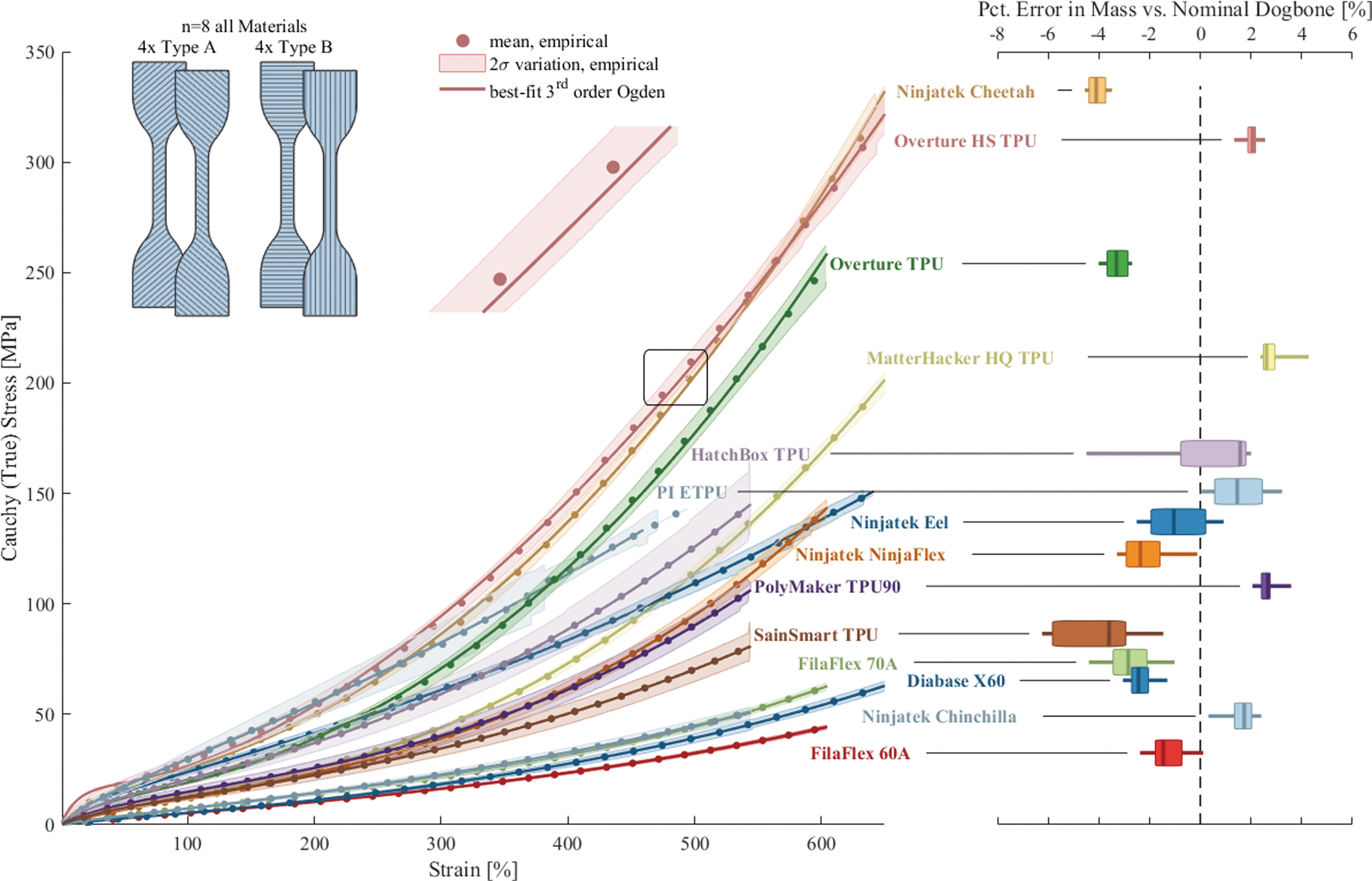
Empirical stress–strain curves for 3D printable soft materials tested in uniaxial tension according to ASTM D412, eight test samples per filament type. Circular marks indicate mean of empirical data, shaded region represents 2σ (95%) confidence bounds, and solid bold lines indicate best-fit third-order Ogden hyperelasticity model. Upper left inset shows infill orientation for samples, which were tested to failure, 550%, or 600% strain depending on material type. Right subplot shows percent error in mass of as-fabricated samples compared with a geometrically perfect sample, displayed in boxplot form (shaded rectangle covers the 25th–75th percentile, horizontal line stretches between the extrema, and vertical line lies at the mean). Softer filaments appear to be more prone to underextrusion, although multiple exceptions to this trend are evident. For color representation of this figure, the reader is referred to the online version of this article.
Test specimens were designed and tested according to ASTM standard D412 (Die C, 33 × 6 × 1.6 mm test region), Test Methods for Vulcanized Rubber and Thermoplastic Elastomers—Tension. 8 Samples were stretched to failure or 600% engineering strain, dictated by the maximum travel available on the load frame used for this characterization (810E5 All-Electric Dynamic Test Machine, Test Resources). Testing was performed on eight samples of each material, divided into two groups (A and B), with infill direction-oriented 45° and 90° offset from the pull direction, respectively.
Hyperelasticity model selection
Empirical data show high repeatability across fabricated samples, indicating consistency in fabrication and test execution. We quantify this repeatability by computing the coefficient of variation (CV) inside each set of test data, and report mean CV below 5% for all material datasets (Table 1). We convert extension distance and tensile force data measured during testing into stress–stretch quantities by accounting for as-fabricated cross-sectional area and test region length.
Soft, 3d-Printable Materials Tested in This Work, Ranging in Nominal Shore A Hardness from 60 to 95
Mean CV for each dataset remains under 5%, indicating low variability between replicates. Coefficients for best-fit first-, second-, and third-order Ogden hyperelasticity models are tabulated, along with Standard Error of Estimate S and AIC (machine-precision values available at www.SoRoForge.com). Increasing the order of the Ogden model improves agreement to empirical data (S strictly deceases), but AIC penalizes models with increasing complexity and suggests that a second-order Ogden model preferable for most materials tested (bold typefaces indicates optimal model choice among three tested based on AIC). Units of μi coefficients are MPa, all other data are unitless.
CV, coefficient of variation; TPU, thermoplastic polyurethane.
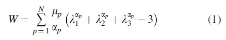
We fit test data to first-, second-, and third-order Ogden model, which quantifies the strain energy density W of a material point as a function of its principal stretches
The Ogden model is a general and highly accurate
3
model for hyperelastic solids, is applicable for strains beyond 400%,
9
and can be reduced to the simpler neo-Hookean or Mooney–Rivlin models with specific choices of N and
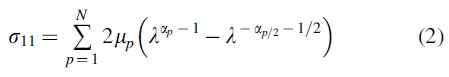
Taking the derivative
Results
Curve fitting is performed on the mean stretch–true stress response of each material to find values of the Ogden coefficients
where n is the number of empirical datapoints, yi is empirical data,
C onclusion
We present a database of 3D printable soft material models, lowering barriers to the wider adoption of simulation soft robotics research. We describe sample fabrication, test procedures, and fitting procedures, adding to earlier work 3 in creating a standardized method for mechanical characterization of materials relevant to soft robotics.
We hope this work spurs adoption of standardized test procedures and hyperelasticity models for common soft robotic materials and shifts focus toward more specialized characterization. In particular, some TPUs tested here exhibit viscoelasticity that falls beyond the scope of this work, but is vital to characterize for soft robotic applications operating in high strain rate contexts. Additionally, further electromechanical characterization of conductive filaments is needed.
Footnotes
Authors' Contributions
L.S.: Conceptualization, Data Curation, Formal Analysis, Investigation, Visualization, and Writing—original draft. R.M.: Supervision, Funding Acquisition, and Writing—review and editing.
Author Disclosure Statement
No competing financial interests exist.
Funding Information
This work is supported by lab startup funds provided by the University of Colorado.