
Abstract
Abstract
Fused filament fabrication (FFF) has opened new opportunities for the effortless fabrication of complex structures at low cost. The additively manufactured lattice structures have been widely used in different sectors. However, the parts fabricated through FFF suffered from poor surface and dimensional characteristics. These disadvantages have been overcome by using different post-processing techniques. The present investigation has been focused on the post-processing of flexible lattice structures through chemical treatment methods. The flexible lattice structures have been fabricated by using thermoplastic polyurethane material. Body-centered cubic lattice structures have been chosen for the present study. The fabricated lattice structures have been post-processed using dimethyl sulfoxide solvent through the chemical immersion method. The response characteristics chosen for the present study were surface roughness, compressive strength, and dimensional accuracy. The measurement has been taken before and after the chemical treatment method for comparison purpose. The results of experimental studies depicted that the proposed methodology significantly enhanced the surface quality and dimensional accuracy, whereas compressive strength has been observed to be slightly reduced after the post-processing method.
Introduction
Cellular structures are porous materials that are present in nature and exhibit properties such as lightweight, high strength, and high energy absorption capabilities. 1 Lattice structures are open cell cellular structures modeled by the repetitive arrangement of struts. 2 These structures are highly compatible with various engineering applications where high strength to weight ratio and energy absorption properties are required. 3
Some of the major application areas of lattice structures are shock absorbers, implants, scaffolds, prosthetics, turbine blades, energy storage applications, etc. 4 The properties of lattice structures depend on the unit cell configuration and constituent material. The lattice structures are further classified as bending-dominated and stretching-dominated structures depending on the deformation mechanism experienced by the struts. 5
The bending-dominated structures are characterized by the excellent energy absorption capabilities, whereas stretching-dominated structures exhibit high strength.4,6 Body-centered cubic (BCC) lattice structures are bending-dominated lattice structures that have been recently explored by researchers due to their design simplicity and scalability. 7
Some of the conventional methods used for manufacturing lattice structures are investment casting, laser cut out lattice, and sheet forming. 8 However, the major problems associated with these methods are that they are not well suited for the fabrication of complex and well-defined configurations. 9 These limitations have been overcome by rapidly growing advanced manufacturing technology, that is, additive manufacturing (AM), which is based on layer-by-layer addition of material to develop the desired product. 10 The other advantages associated with AM methods that has made it popular are high-design freedom and low wastage of materials. 11
Most of the research work has been focused on the investigation of the properties of lattice structures fabricated by the Selective Laser Sintering process, as the process has the advantage of building lattices with high dimensional accuracy. However, it is associated with high production cost. 12 Fused filament fabrication (FFF) is a low-cost AM technique that works on the principle of extruding material in molten state on the build platform. 13
Recently, a few researchers have tried to investigate the suitability of the FFF process for the fabrication of lattice structures. Rifaie et al. investigated the effect of different configurations of BCC lattice structures on their compressive strength. They modified the BCC lattice structure by adding vertical struts in different orientations and fabricated them by the fused deposition modelling (FDM) printer using acrylonitrile butadiene styrene (ABS) material.
The strength of the structures has shown significant improvement due to the design modifications. 14 Mishra et al. have compared the compressive strength of the triply periodic minimal surface lattice structures made from ABS and polylactic acid (PLA). They observed that PLA-based structures showed higher strength as compared with ABS-based lattice structures. 15
The manufacturability of the gyroid lattice structures using the FDM printer has been investigated by Maharjan et al. They have concluded that the lattice structures with the smallest unit cell size and the largest volume fraction have the highest compressive strength. 16 Gautam et al. have investigated the compressive strength of ABS-based Kagome lattice structures. They concluded that the polishing of lattice structures for 5 min with 90% acetone by vol. improves the strength of the lattice structures. 17
The literature studies related to lattice structures depicted that most of the research work has been focused on the fabrication of lattice structures using ABS and PLA, which are the most widely used materials processed through FFF. 18 There is a need to explore more materials, as the properties of lattice structures depend on the constituent material's properties.
The FFF process also suffers from disadvantages such as poor surface quality and dimensional accuracy, which inevitably affect the strength of build parts. 19 The other challenges associated with the process are related to environmental sustainability in terms of raw material usage, energy consumed, and wastage produced during the printing.
The selection of low infill percentage, higher layer height, and high printing speed leads to less energy consumption during the FFF process. 20 Researchers have focused on the two methods for overcoming these disadvantages. The first method is the optimization of process parameters associated with the FFF process for improved physical and mechanical properties of the build parts. 21 However, this method has been found to be effective only up to a certain level.
The other method that has been found to be more successful as compared with the optimization method is post-processing of the build parts. The post-processing methods can be categorized into three domains as mechanical, chemical, and thermal treatment methods. The thermal treatment methods have been categorized into surface heating and thermal annealing.
The thermal annealing method involved heating of the samples at a fixed temperature for a particular time interval and slowly cooling them to room temperature. 22 The mechanical finishing of the parts utilized mechanical forces for improving the properties of the parts, whereas the chemical method involves the usage of different chemicals for treatment of the parts. 23
The different types of the mechanical method utilized for post-processing by the researchers are abrasive machining, computer numerical control machining, laser treatment, sand blasting, magnetorheological finishing, etc. 24 The chemical treatment methods are further categorized as chemical dipping, spraying, vapor smoothening, etc. 25 The advantages of using chemical methods over mechanical methods are low cost, less processing time, no requirement of machine setup, and less human intervention.26,27
However, it has been observed from literature studies that most of the research work has been focused on the post-processing of the ABS and PLA based parts fabricated through the FFF process. 28 Some researchers have focused on the processing of pure material and composite materials and compared their properties. Kechagias et al. investigated the effect of processing of PLA-based nanocomposites made by mixing carbon black (CB) in different proportions.
They have utilized economical CO2 laser cutting for the post-processing of build parts. They have observed that the surface roughness of the nanocomposite parts increases with the increase in percentage of the CB as compared with pure PLA. 29
There is a need to explore post-processing of the other polymers, which can open new opportunities for FFF build parts. The novelty of the present research work is that the suitability of the chemical treatment method has been explored for the post-processing of highly flexible parts. Thermoplastic polyurethane (TPU) polymer comes under the category of thermoplastic elastomers. 30 These are characterized with high elasticity, high tear strength, high abrasion resistance, and chemical resistance that are responsible for its growing popularity for making flexible parts.
The TPU has been widely used in making wearable electronics, shoe soles, prosthetics, textiles, 31 sports equipment, etc. 32 The post-processing of TPU parts built through the FFF process can make new paths for making flexible functional parts with complex structures.
This comprehensive study emphasizes the physical and mechanical properties of chemically treated BCC lattice structures built through the FFF process. The BCC lattice structures have been built using TPU material with different layer thickness. The chemical immersion method has been utilized for post-processing of lattice structures. The surface roughness, dimensional accuracy, surface characteristics, and compressive strength of the treated and untreated lattice structures has been studied and compared.
This study helps to explore the effect of the chemical treatment method on the compressive behavior of flexible BCC lattice structures as well as on the surface that enhances the characteristics associated with the FFF-printed lattice structures.
Materials and Methodology
Materials
TPU, a category of thermoplastic elastomers in the filament form of white color and 1.75 mm diameter, has been purchased from Esun Industrial Co., Ltd. It has been utilized for building lattice structure samples in the present investigation. The mechanical characteristics of the TPU parts have been measured in the present investigation by performing tensile and compression testing. The samples were printed with the dimensions as shown in Figure 1a and b for tensile and compression testing, respectively.
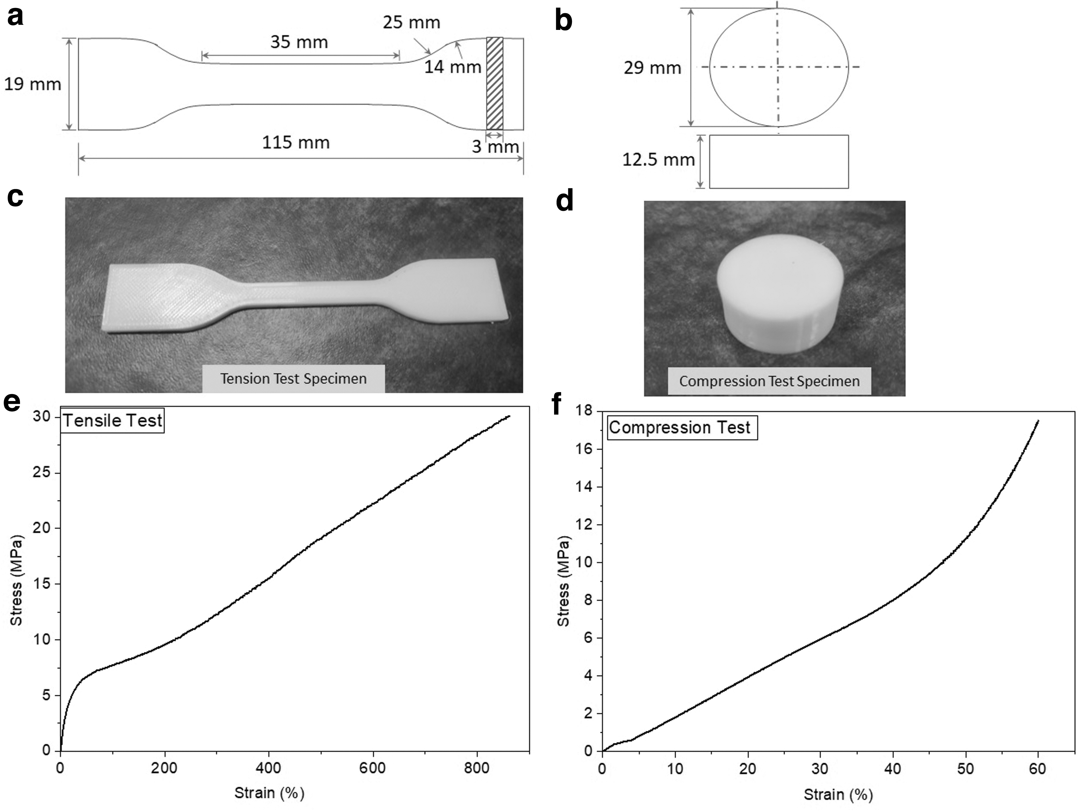
Mechanical characterization of TPU parts
The as-printed parts for both the testing are shown in Figure 1c and d, respectively. ASTM D412 C standard has been followed for tensile testing, whereas ASTM D575-19 standard has been used for compression testing. The stress-strain graph for tensile testing is shown in Figure 1e from which it has been observed that the tensile strength of the TPU part is 30.1 MPa.
Similarly, the compressive strength of the TPU parts has been found to be 17.5 MPa from the stress-strain curve provided in Figure 1f. The dimethyl sulfoxide (DMSO) solvent with 99.99% purity has been utilized for the chemical treatment of TPU parts in the present study. DMSO is an organic polar solvent that is extracted from wood and widely used for getting relief from joint and muscular pain. It is a non-harmful, colorless, water miscible, and non-synthesized liquid.
Methodology
The chemical immersion process has been utilized for the post-processing of flexible lattice structures in the present study. Creator Pro printer with a build accuracy of ±0.1 mm based on the FFF process has been used for printing flexible BCC lattice structures using TPU. The printer has a total build volume of 150 × 140 × 140 mm3 with X–Y Positioning Precision of 0.011 mm and Z Positioning Precision of 0.0025 mm.
The dimensions of unit cell and lattice structure are given in Figure 2. The unit cell with a strut radius of 4 and 10 mm distance between strut length has been modeled using SolidWorks18 software (Fig. 2a). The unit cell has been scaled four times in three directions to design a lattice structure with dimensions of 40 × 40 × 40 mm (Fig. 2b).
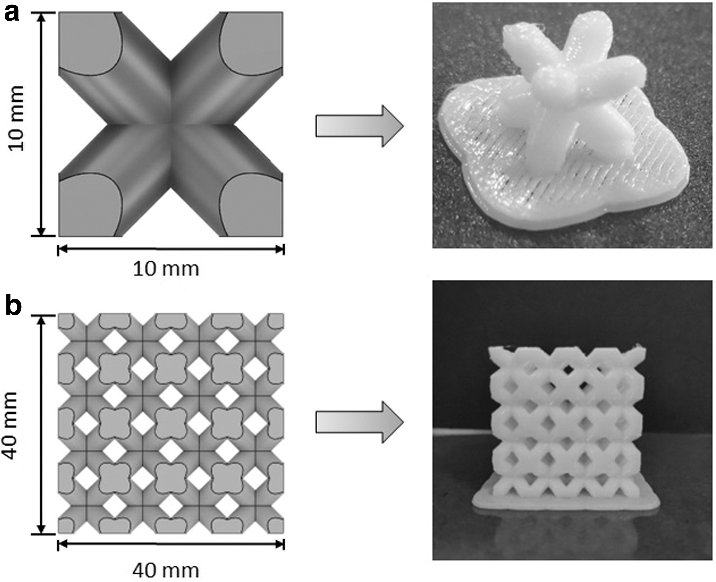
CAD model and as-printed
The values of process parameters selected for the fabrication of lattice structure are provided in Table 1. Three different layer thicknesses have been chosen for the present study to investigate the efficacy of the chemical treatment method for the processing of flexible lattice structures.
Selected Process Parameters
The different steps of research methodology followed for the present investigation have been shown in Figure 3. The process starts with the designing and fabrication of BCC lattice structures. Three replicates of the lattice structures have been fabricated to ensure the accuracy of the results. The chemical immersion technique has been performed further for the post-processing of these structures in the second stage.
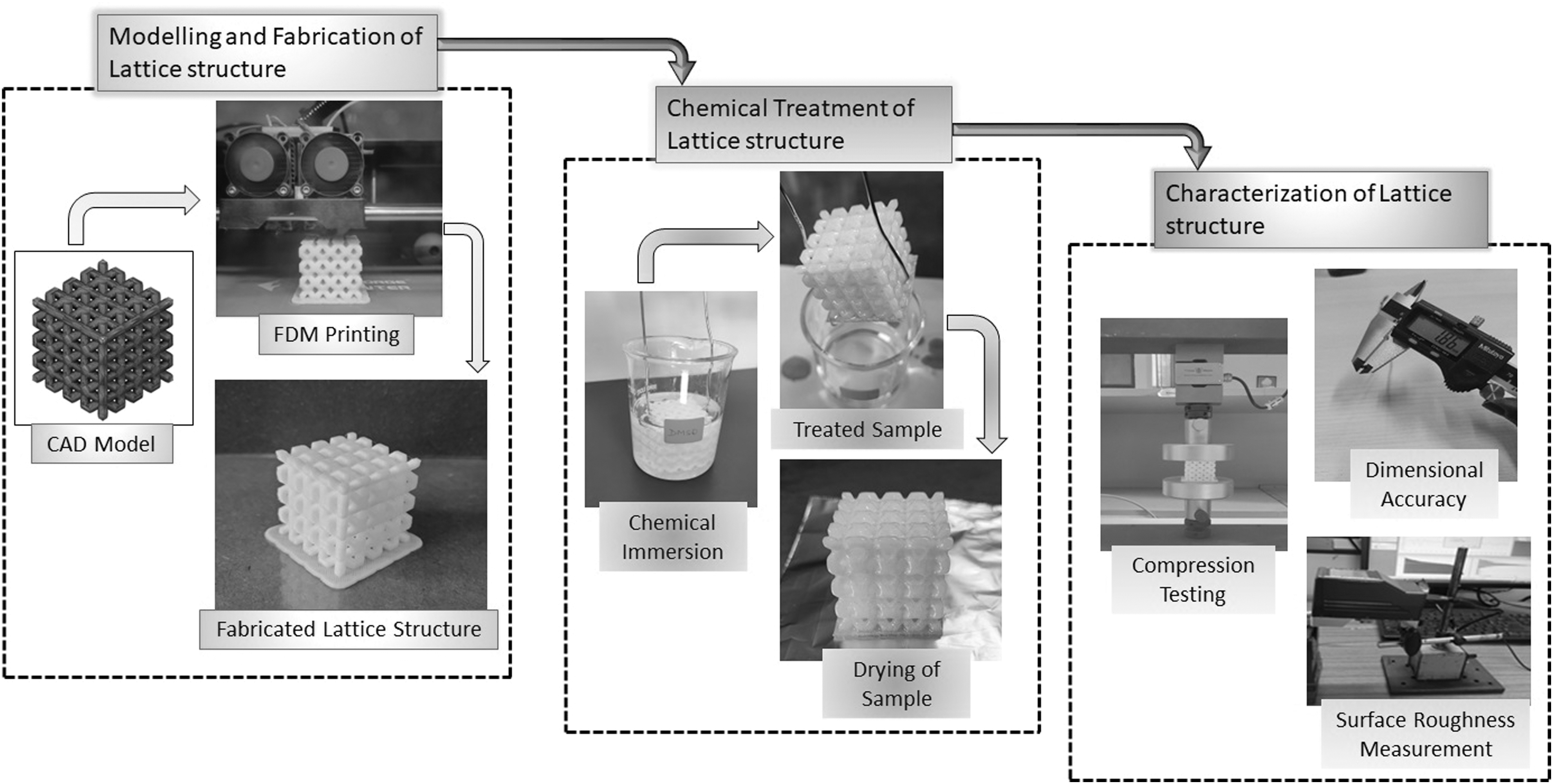
Research methodology.
The as-build lattice structures were dissolved in the DMSO chemical for the particular immersion time at room temperature. The immersion time of 120 s has been chosen based on the different trial experiments performed. The treated samples have been left for drying at room temperature for >28 h.
The next stage included the characterization of chemically treated and untreated lattice structures. The struts of same diameter as lattice structures have been fabricated using TPU for measuring the surface roughness of untreated samples. These struts were further treated for measuring the surface roughness of chemically treated samples. The surface roughness value in terms of Ra and Rt was measured using Tesa Rugosurf 10G surface roughness tester.
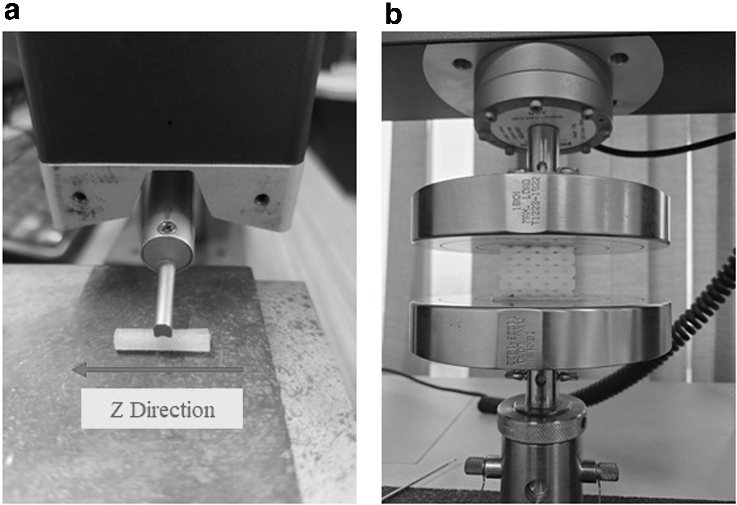
The values have been measured at different points, and average values were taken for comparison purpose. The surface roughness has been measured in the Z direction, as shown in Figure 4a. The details of the surface roughness measurement have been provided in Table 2. The compression testing has been chosen to investigate the effect of chemical treatment on the mechanical response of lattice structures.
Measurement of
Surface Measurement Details
Tinius Olsen testing machine has been utilized for the testing purpose for both treated and untreated lattice structures, as shown in Figure 4b. The crosshead speed of 1 mm/min has been chosen for the compression testing. Mitutoyo digital vernier caliper has been utilized for investigating the dimensional accuracy of the lattice structures in terms of deviation in the diameter of the struts before and after the treatment. The instrument used has been characterized by the 0–150 mm measuring range and 0.01 mm least count.
The surface morphology of the lattice structures before and after the chemical treatment has been investigated using the digital microscope. The microscope has 300 × magnification, and MicroCapture Pro software has been used for the analysis of the surface. The discussion of the obtained results has been presented in further sections.
Results and Discussions
The present study investigated the effect of chemical treatment on the behavior of BCC lattice structures fabricated through the FFF process. The results obtained after performing surface roughness measurement, compression testing, surface morphology, and dimensional deviation have been discussed in detail in this section. The results of all the testing for both the untreated and treated samples have been discussed for the comparison purpose.
Analysis of surface roughness
The surface roughness of the samples has been measured before and after the chemical treatment of struts that were fabricated with the same diameter as that of lattice structures. The experimental results obtained for values of Ra and Rt are given in Table 3 respectively for different layer thickness.
Experimental Values for Surface Roughness Measurement (Ra and Rt)
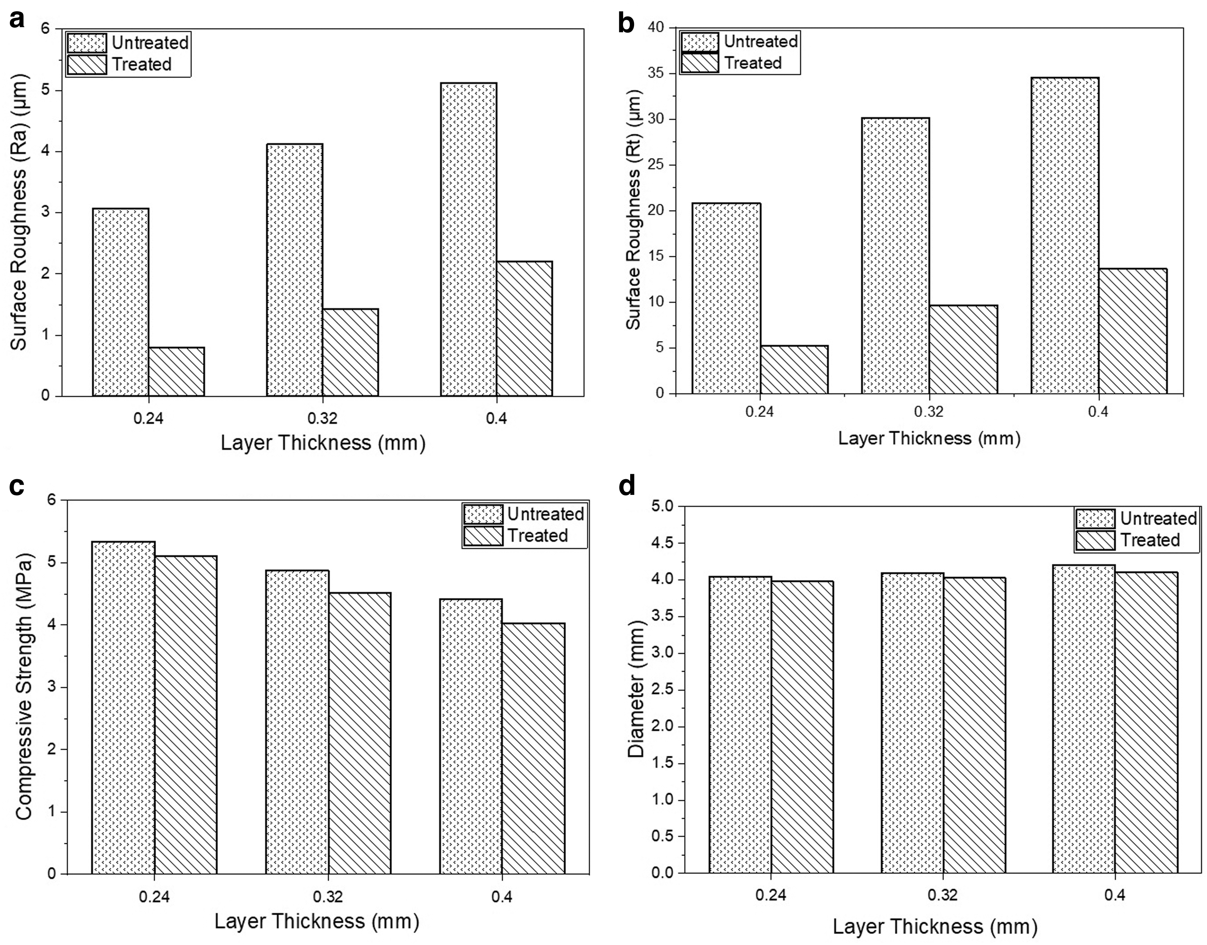
The maximum value for the average surface roughness (Ra) of 5.126 μm has been observed in the case of layer thickness of 0.4 mm before chemical treatment. The minimum average Ra value of 3.069 μm was obtained for the untreated samples with a layer thickness of 0.24 mm. This can be related to the phenomenon of increasing the surface roughness values with the increase in the layer thickness.
The increase in the layer thickness causes an increase in the stair stepping effect of the FFF fabricated parts, which significantly deteriorates the surface quality by increasing the surface roughness values. This can also be observed from the 2D surface profile given in Figure 5 for different layer thickness of untreated and treated samples. The high values of peak and height for samples with 0.4 mm (Fig. 5a) layer thickness as compared with samples with layer thickness of 0.32 mm (Fig. 5b) and 0.24 mm (Fig. 5c) confirmed the same.
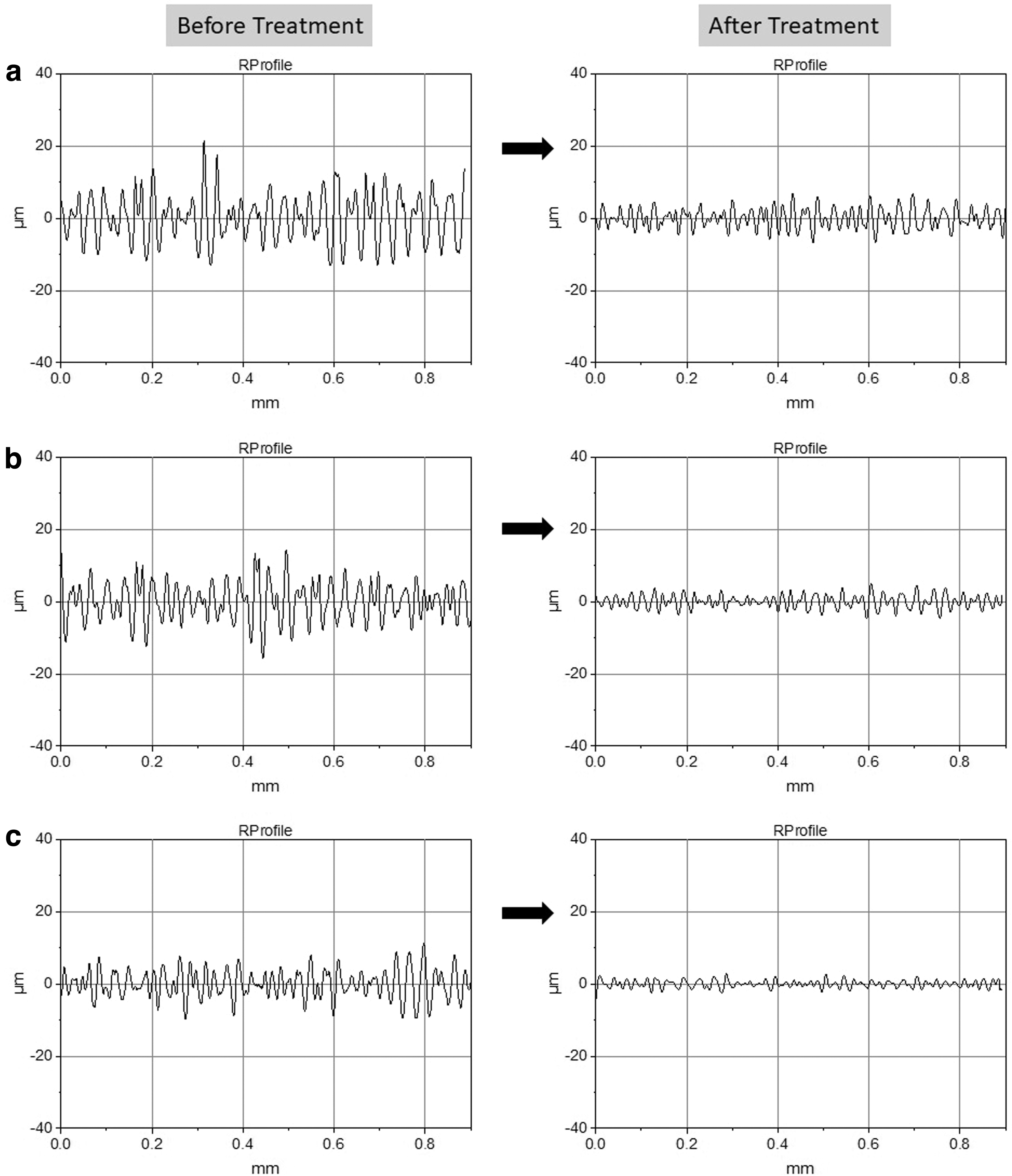
Surface roughness profile of parts with layer thickness
The chemical treatment method significantly improved the surface quality of TPU lattice structures, as observed from Table 3. The minimum average Ra value obtained after the chemical treatment method was 0.802 μm for samples with 0.24 mm layer thickness. The minimum average Rt value obtained after the chemical treatment method was 5.287 μm for samples with 0.24 mm layer thickness.
The chemical treatment method dissolved a layer of the surface exposed to the solvents, which led to a smooth surface. The average Ra and Rt values for all the samples before and after the treatment were compared. The average Ra value for samples with 0.4 mm layer thickness decreases to 2.206 μm and 0.32 mm layer thickness sample to 1.432 μm.
The percentage improvement in Ra values of 60.48%, 65.24%, and 74.04% has been obtained in the treated samples with layer thickness of 0.4, 0.32, and 0.24 mm, respectively. Similarly, the percentage improvement in the Rt values has been observed as 60.43%, 67.95%, and 74.60% for samples with layer thickness of 0.4, 0.32, and 0.24 mm, respectively.
The layer-by-layer addition of the materials during the FFF process is the major cause of poor surface quality of the fabricated parts. The surface of the FFF build parts is characterized by the peaks and valleys. When the part surface is post-processed using chemical finishing methods, the solvents dissolve the exposed surface and flowing of these solvents leads to the formation of a smooth and plane surface. Thus, the chemical treatment methods improve the surface finish of the treated parts. 33 The bar chart showing the effect of layer thickness on the Ra and Rt values for both untreated and treated samples is shown in Figure 6a and b respectively.
Bar chart showing variation of surface roughness with layer thickness,
Analysis of surface texture
The surface of the BCC lattice structures has been analyzed before and after the chemical treatment method using the digital microscope. The images obtained for the different layer thickness are shown in Figure 7. The printing lines are clearly visible in the samples fabricated with a layer thickness of 0.4 mm (Fig. 7c) and 0.32 mm (Fig. 7b) whereas it is less visible in a layer thickness of 0.24 mm (Fig. 7a) before treatment.
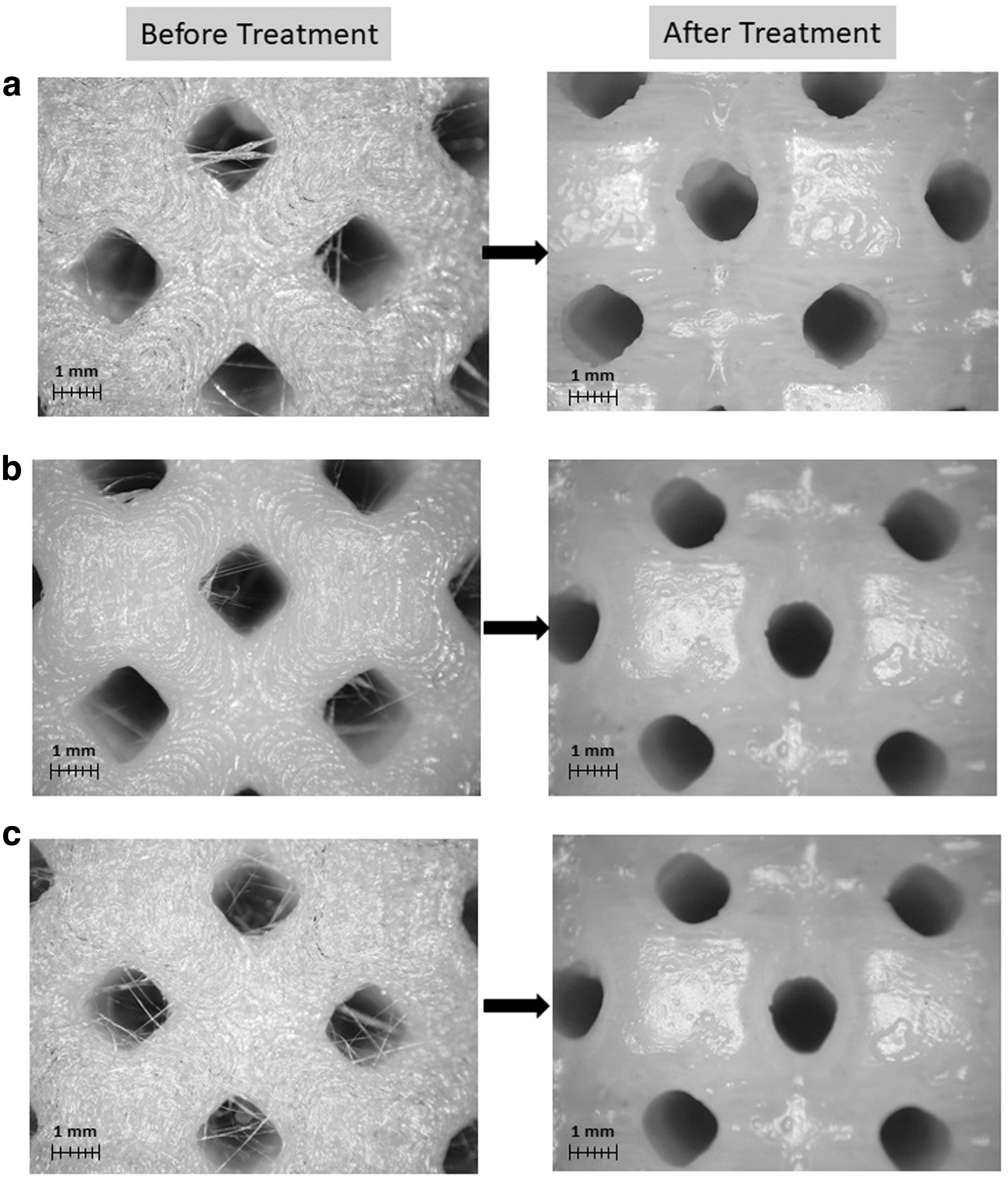
Microscopic images of the samples before and after treatment with layer thickness,
The stringing effect is also clearly visible in the micrographs. The stringing effect is the undesired characteristic of the FFF fabricated parts. The thin hair like threads are observed in some areas of the fabricated parts where no printing takes place in this effect. This effect usually deteriorates the aesthetics of the fabricated part, making it unsuitable for use as a functional product. In the present investigation, as the lattice structures have been chosen for the investigation that consists of open pores, hence the stringing effect is more dominant.
The surface texture after the chemical treatment process is characterized by the smooth surface, as depicted in Figure 7. The smooth surfaces of BCC lattice structures were formed after the chemical treatment process using DMSO solvent for 120 s. It has also been observed that the stringing effect disappeared in the open pores of the lattice structures, as the polymer threads got dissolved by the solvent.
The micrographs of the treated surface for samples with a layer thickness of 0.4 mm revealed that the layers were still visible, which led to high surface roughness values after the chemical treatment method as compared with samples with other layer thickness. The quality of the smooth surface is superior for the case of layer thickness 0.24 mm. Thus, it can be concluded by analyzing the surface texture that the quality of the surface improves as the layer thickness decreases within a fixed interval of 120 s immersion time.
Analysis of compressive strength
The experimental results obtained after compression testing are provided in Table 4. The maximum average value of the compressive strength obtained was 5.34 MPa for lattice structures with a layer thickness of 0.24 mm, and the minimum value was 4.42 MPa for the 0.4 mm layer thickness. The strength of the FFF build part decreases with the increase in the layer thickness. The higher values of the layer thickness cause poor bonding between the layers and large size of micro voids.
Experimental Values for Compressive Strength Measurement
These micro voids act as stress risers and thus lead to a decrease in the strength of the parts. Similarly, the parts built with a lower layer thickness resulted in the intact bonding between the layers due to closely stacked layers, which, in turn, improved the strength. This is the possible reason behind the difference observed in the compressive strength of the parts built with different layer thickness. 34
The compressive strength of the lattice structures was again measured after the chemical treatment method for the comparison purpose. The average values of the compressive strength observed were 4.03, 4.52, and 5.11 MPa for the parts with the layer thickness of 0.4, 0.32, and 0.24 mm, respectively. The percentage reduction in the compressive strength occurred between the range of 5–8%.
A bar chart showing the variation of the strength with the layer thickness has been provided in Figure 6c. The chemical treatment method led to a slight reduction in the compressive strength of the lattice structure. The possible reason behind this observation was the removal of material during the chemical immersion method. The BCC lattice structures are hollow structures that cause more surface areas to be exposed with the DMSO solvent.
As the exposed surface area increased, more removal of material from the surface took place, which, in turn, decreased the compressive strength of the lattice structures. However, the percentage reduction observed was not significant; hence, this can be compromised for achieving the parts with better surface quality and dimensional accuracy.
Analysis of dimensional accuracy
The dimensional accuracy of the lattice structures has been analyzed in terms of change in the diameter of the strut in the proposed methodology. The CAD diameter of the struts for the BCC lattice structures fabricated was 4 mm. The measurement has been taken at six different positions to maintain the accuracy of the results. The results obtained after the measurement are provided in Table 5.
Experimental Values for Strut Diameter Measurement
The maximum values of average diameter obtained for the untreated parts were 4.21, 4.10, and 4.05 mm for samples built with a layer thickness of 0.4, 0.32, and 0.24 mm, respectively. It has been observed that the diameters of the fabricated BCC lattice structures were more than the CAD diameter, which was 4 mm. The possible reasons behind obtaining this difference in the diameters were the expansion of material during extrusion and the stair stepping effect.
It has been observed that due to layer-by-layer addition of material in the FFF process, the fabricated parts are characterized by the variation in the dimensions. 35 The higher layer thickness causes the increase in the chord length, which ultimately causes increased dimensions. The nozzle temperature also affects the dimensional accuracy of the parts built through the FFF process.
The increase in the nozzle temperature results in more dimensional variation as the viscosity of molten material increases. 36 The maximum variation of 5.25% has been observed in the diameter of lattice structures made with 0.4 mm layer thickness. The minimum deviation of 1.17% has been found for structures built with 0.24 mm layer thickness. The high value of layer thickness causes more variation in dimensions of the parts, whereas the low layer thickness leads to fabrication of more dimensionally accurate parts.
The diameter of the struts of BCC lattice structures has also been measured after the chemical treatment with DMSO solvent for 120 s. The maximum values of average diameter obtained for the chemically treated parts were 4.11, 4.035, and 3.98 mm for samples built with layer thickness of 0.4, 0.32, and 0.24 mm, respectively. The percentage variation in diameters as compared with the CAD model also significantly reduced to 2.75%, 0.875%, and 0.458% for samples with 0.4, 0.32, and 0.24 mm layer thickness, respectively.
The bar chart showing the variation of diameters with the layer thickness is shown in Figure 6d. The pore size deviation measured through microscopic images taken from a digital microscope is also shown in Figure 8. The pore size as shown in the figure varies from 6 ± 0.5 mm for untreated samples to 7 ± 0.5 mm for the treated sample.
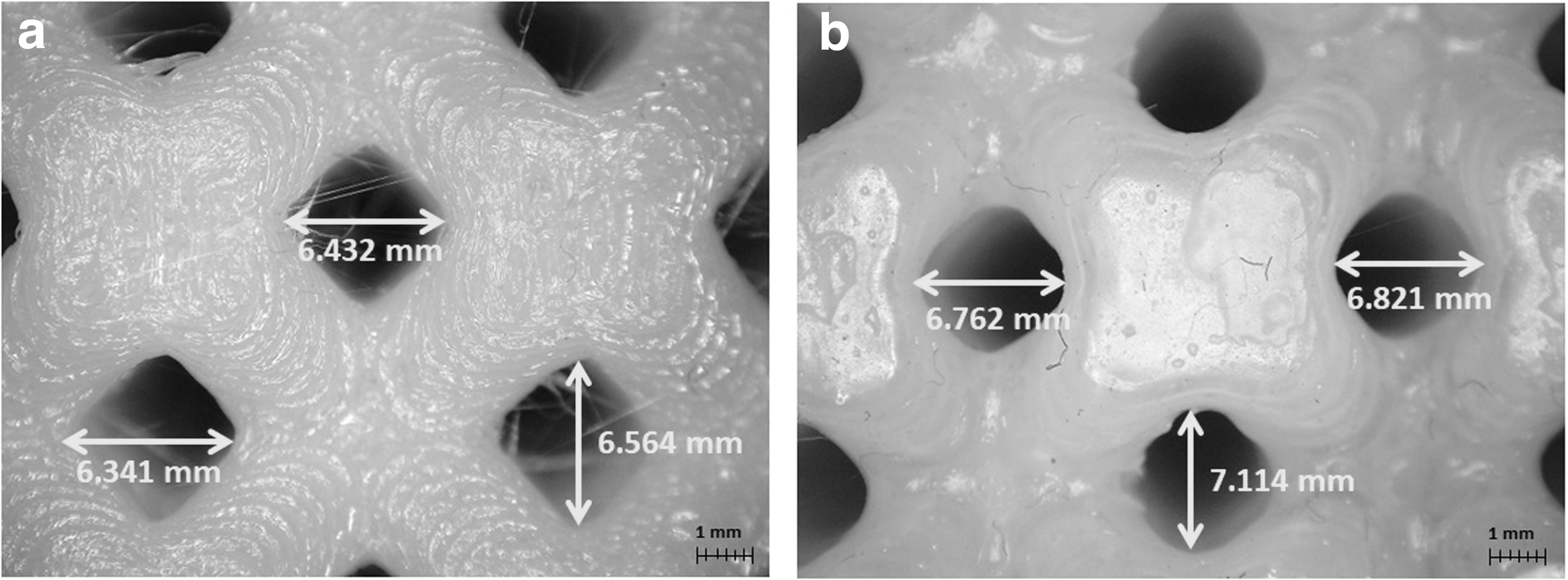
Pore size measurement
The pore size increases as more material dissolved during the chemical treatment process. The diameter size reduces after the treatment process. The dissolving of the thin layer of the surface exposed to the solvent resulted in the reduced dimensions, making it close to the CAD model dimensions.
Conclusions
The present investigation has been focused on the investigation of the suitability of the chemical treatment method for the post-processing of the TPU-based BCC lattice structures. The lattice structures have been fabricated at three different layer thickness of 0.4, 0.32, and 0.24 mm, respectively. The lattice structures were chemically treated with the DMSO solvent through the chemical immersion method for 120 s. The following conclusions have been drawn from the present investigation:
The proposed chemical treatment method has been found to be successful for the post-processing of the BCC lattice structures made of TPU material and fabricated through the FFF process. The chemical finishing method has been found to be suitable in improving the surface quality of the BCC lattice structures with up to 74.04% improvement in the surface roughness. The analysis of the surface texture of the BCC lattice structure after the chemical treatment resulted in a very smooth surface. The compressive strength of the BCC lattice structures was observed to be slightly reduced after the chemical finishing, which can be compromised with the improvement in surface quality of the lattice structures. The dimensional accuracy of the BCC lattice structures in terms of the change in the diameter of the strut has been found to be significantly improved after the chemical treatment method.
The present investigation can be extended in future by applying optimization techniques for the post-processing of the flexible parts made through TPU. The parameters associated with the FFF process and the chemical treatment method can be optimized for improving the quality characteristics of the TPU parts.
Footnotes
Authors' Contributions
N.D.: Conceptualization, methodology, investigation, and writing—manuscript preparation; P.K.J.: Reviewing—comments and revisions, supervision.
Author Disclosure Statement
No competing financial interests exist.
Funding Information
No funding was received for this article.