
Abstract
3D printing is an indispensable technology in modern life and is widely used in aerospace, exoskeleton, and architecture. The increasing accuracy requirements of 3D printed objects in these fields require high-precision measurement methods to obtain accurate data. Based on the precision measurement requirements, in this study, a fast multifrequency phase unwrapping method based on 3D printing object appearance acquisition is proposed. By performing standard image acquisition of 3D printed objects that are not limited to materials and sampling locations, the surface shape and texture details of the objects can be accurately reconstructed using this method, independent of ambient light, with high robustness. Compared with the conventional multifrequency method, the required projection pattern is reduced from 12 to 9 and the overall measurement efficiency is improved by 25%, while maintaining the advantages of the independent pixel calculation method of the multifrequency method. In addition, the effectiveness of the method is experimentally verified by complex surface reconstruction experiments and plaster model experiments, which provide accurate measurement accuracy with high efficiency and precision. Therefore, the method can provide accurate measurements for 3D printed objects.
Introduction
3
However, accurate measurement of 3D printed objects faces several challenges. First of all, printed objects may have complex geometries, including fine details and curved surfaces, requiring high-precision measurement methods to obtain accurate data. In addition, the surface of printed objects may have features such as nonuniform material distribution or gloss variation, requiring processing of these surface features to obtain accurate measurements. Finally, the data obtained from 3D printed objects usually include multiple sources such as depth images and phase information, which require effective data processing and analysis to obtain accurate measurement results.
Based on these challenges, streak projection profiling, a commonly used measurement technique, provides a solution for the accurate measurement of 3D printed objects. Fringe projection profilometry5,6 (FPP) refers to the quantification of fringe distortion by its phase distribution, which can be converted into the surface profile of the measured object. FPP mainly includes two techniques, fourier transformation profilometry7,8 (FTP) and phase shifting profilometry 9 (PSP). PSP provides higher measurement resolution and accuracy because it eliminates the interference from ambient light and is more widely used.10,11
Whether it is FTP or PSP, both techniques estimate the phase distribution by calculating the inverse tangent function. When the full field contains one periodic phase, the resolution of the measurement is low and vulnerable to environmental interference, so the system needs to project grating stripes containing multiple periodic phases for measurement, and phase expansion is necessary to obtain a continuous phase distribution and establish correspondence between pixels.
Phase unwrapping methods mainly include temporal phase unwrapping12–14 and spatial phase unwrapping.15,16 The spatial phase unwrapping analyzes the spatial neighborhood information unwrapping, and the measurement speed is fast, but the premise is that the phase is continuous. If the whole field contains noncontinuous phases,17,18 it is vulnerable to the interference of noncontinuous parts and noise and error. Temporal phase unwrapping uses the time domain to obtain additional information, that is, the fringe order is calculated by projecting additional fringes to obtain the wrapped phase. The advantage is the ability to analyze discontinuous objects, where each spatial pixel in the measurement data is independent and noisy pixels do not disrupt the whole unfolding process.
Multifrequency method in temporal phase unwrapping 19 is more robust than the number-theoretic unwrapping method, and under the same conditions, multifrequency provides a larger range of phase nilpotency in the same setting, which was first proposed by Huntley and Saldner 20 in 1993.
To improve the projection efficiency with high accuracy, Haitao et al. 21 proposed a new phase-shifting contour measurement method that can achieve temporal phase unwrapping while minimizing the fringe pattern, but the edge frequencies of this method must be within a certain range, otherwise the correctness of phase expansion is affected; Limei et al. 22 proposed to combine dual-frequency outlier with dual complementary phase coding to obtain absolute phase information using two sets of sinusoidal fringes and half-order shifted complementary phase coded fringes for phase decoupling; Xinming et al. 23 proposed a unified temporal phase unfolding framework using deep learning, which can effectively mitigate the effect of noise and enhance the reliability of phase unwrapping given the assistance of deep learning, but the work such as collecting and producing the data set is not more efficient due to the inclusion of deep learning; Beiyi et al. 24 proposed a dual-frequency phase unwrapping method, which has improved measurement accuracy and interference immunity compared to single-frequency phase unwrapping.
This study proposes a fast multifrequency phase unwrapping method based on 3D printing object appearance acquisition, which is based on the fusion of four-step phase shift method, multifrequency method, and orthogonal grating projection to improve the overall measurement efficiency while ensuring accuracy. The method pixels are calculated independently, maintaining the advantages of independent pixel calculation of the multifrequency method, and the background intensity and modulation intensity are not used to recover the phase, which is not affected by the ambient light and has high robustness. The method is able to handle surface features and textures of 3D printed objects, overcoming challenges such as complex geometries and inhomogeneous material distributions to provide efficient and accurate measurement results, thus meeting the need for accurate measurements in 3D printed object applications.
Section II highlights the theoretical framework of the method and a detailed elaboration of each part of the framework, as well as a description of the material properties and the measurement device. Section III verifies the effectiveness of the method through accuracy verification, complex object reconstruction, and plaster model reconstruction experiments.
Experimental Procedure
Materials and machines
The measurement system consists of a projector (TI DLP LightCrafter 4500), an industrial camera (Daheng), and a computer. The measured object is a matte surface ceramic standard ball, and the principle diagram of the measuring system is shown in Figure 1.
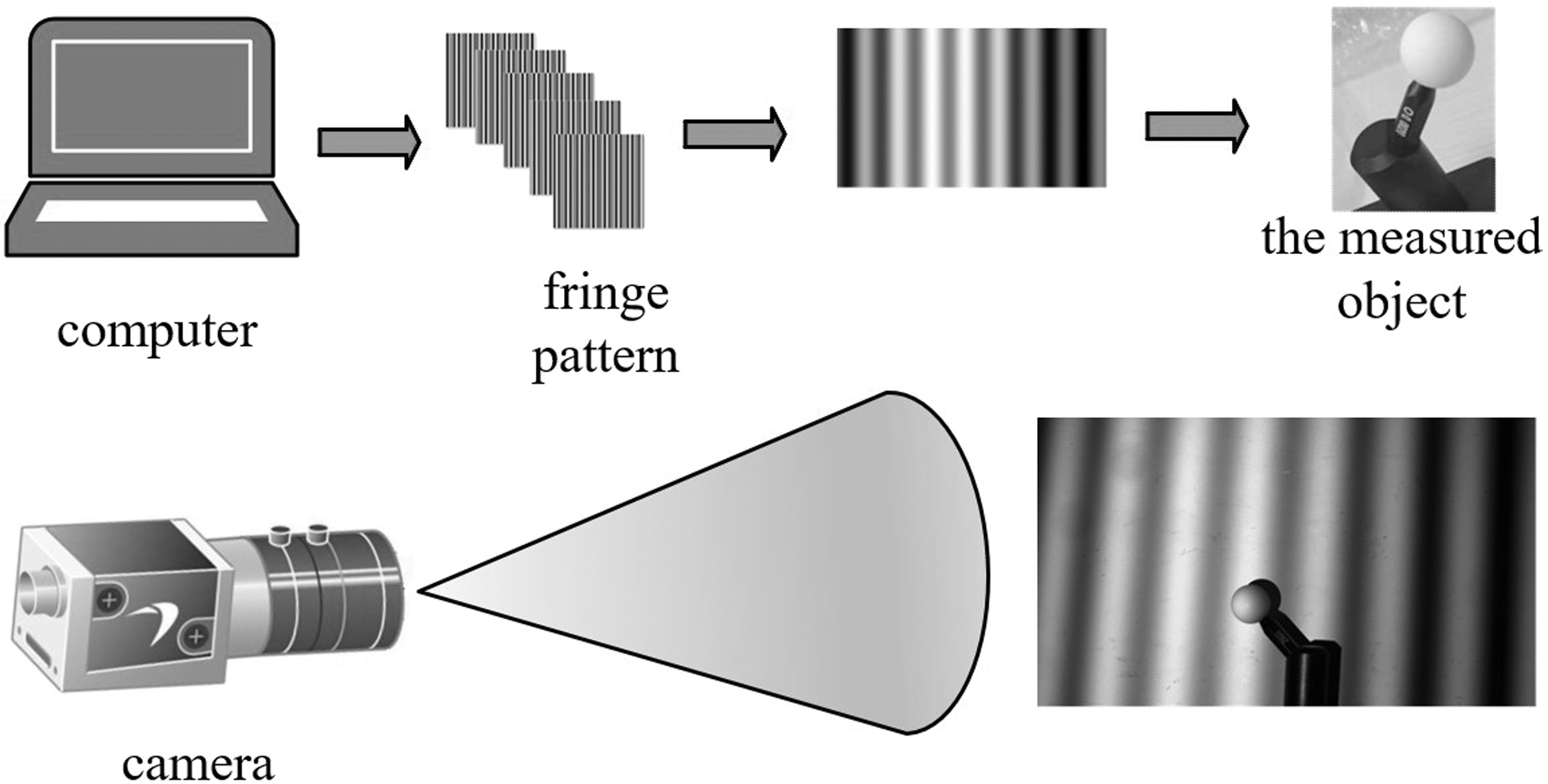
Principle diagram of the measurement system. The stripe image is generated by computer coding, and the stripe image is projected onto the surface of the object to be measured by the projector. The light source of the projector emits light to illuminate the stripe pattern, so that it forms a deformed stripe pattern on the surface of the object. At the same time, industrial cameras capture deformed stripe patterns.
TI DLP LightCrafter 4500 was manufactured by TI® (Texas Instruments), as shown in Figure 2. The DLP LightCrafter 4500 uses a 0.45 WXGA chipset and offers the perfect combination of resolution, brightness, and programmability in a small package. Daheng Industrial Camera was manufactured by DAHENG IMAGE® (Beijing, China), as shown in Figure 3. MER-502-79U3C adopts global exposure CMOS sensor chip, which can work stably in various harsh environments and is a highly reliable and cost-effective industrial digital camera product. The process parameters of projector and camera are included in Table 1.
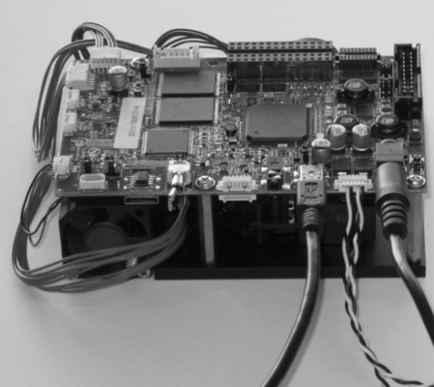
TI DLP LightCrafter 4500.
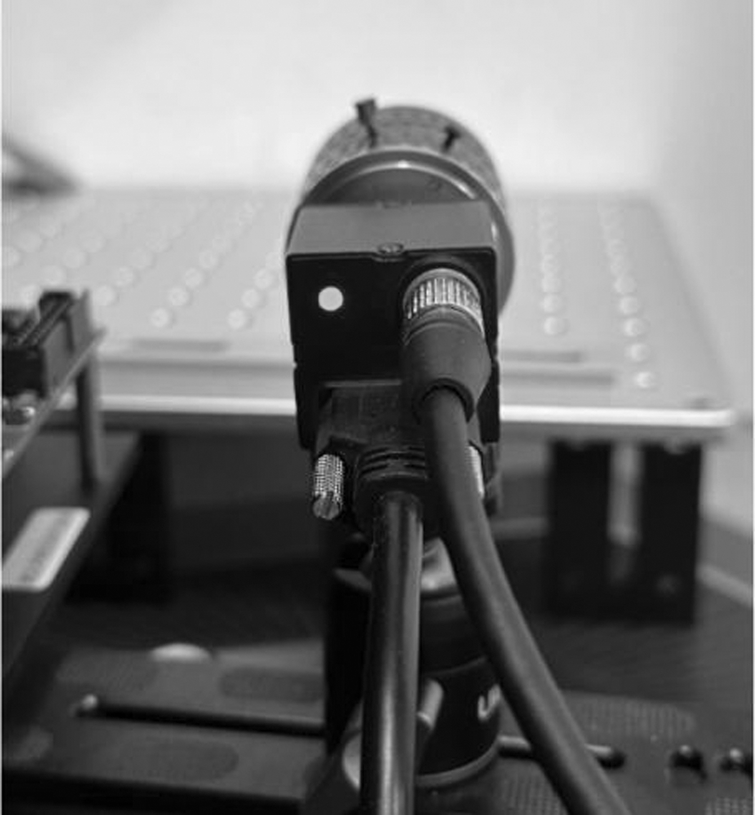
Daheng MER-502-79U3C.
Process Parameters of Projector and Camera
WHL, Width, Height, Length.
Used to verify the accuracy of the method is a matte-faced ceramic standard ball, a precision tool commonly used for optical measurement and calibration. It is made of zirconium oxide (ZrO2), a high-purity ceramic material with properties detailed in Table 2, which has excellent hardness, wear resistance, and chemical stability. Its density per cubic centimeter is as high as 5.95–6.05 g/cm3. Among the four materials commonly used to make ceramic spheres (Si3N4, SiC, Al2O3, ZrO2), zirconia ceramic has a higher toughness of 10 MPa·m1/2 or more and a coefficient of thermal expansion close to that of metal, which can meet the need for a good fit with metal.
Characteristics of Zirconium Oxide
ZrO2, zirconium oxide.
The surface of the ceramic standard ball is treated with a special treatment—matte surface treatment, which gives it a matte surface effect. This treatment can reduce the reflection and scattering of light and improve the accuracy of measurement. Matte finish ceramic standard balls are typically very precise in size, with highly uniform diameters and sphericity. These dimensional characteristics are critical to the accuracy of optical measurements. Although matte-faced ceramic standard spheres exhibit a matte finish, the material itself typically has a high degree of optical transparency. These advantages allow them to be used in a variety of optical measurement and calibration applications.
Algorithm framework
Four-step phase shift method
In this study, a four-step phase-shift algorithm is used to construct the phase equation, then the camera acquires the light intensity expressions for the corresponding four-step phase-shift fringe patterns as:
Where
Principle of multifrequency method
The principle of the multifrequency method is to project the sinusoidal fringe patterns of frequencies fh and fl onto the measured object and extract the wrapped phases of the sinusoidal fringe patterns of fh and fl, respectively. The fringe patterns with the minimum fringe frequency fl are required to cover the whole field of view, that is:
Where
The principle diagram of the multifrequency method is shown in Figure 4. Red is the low-frequency continuous phase, and black is the high-frequency wrapped phase. The high fringe frequency continuous phase (green) can be obtained from the formula (3–5).
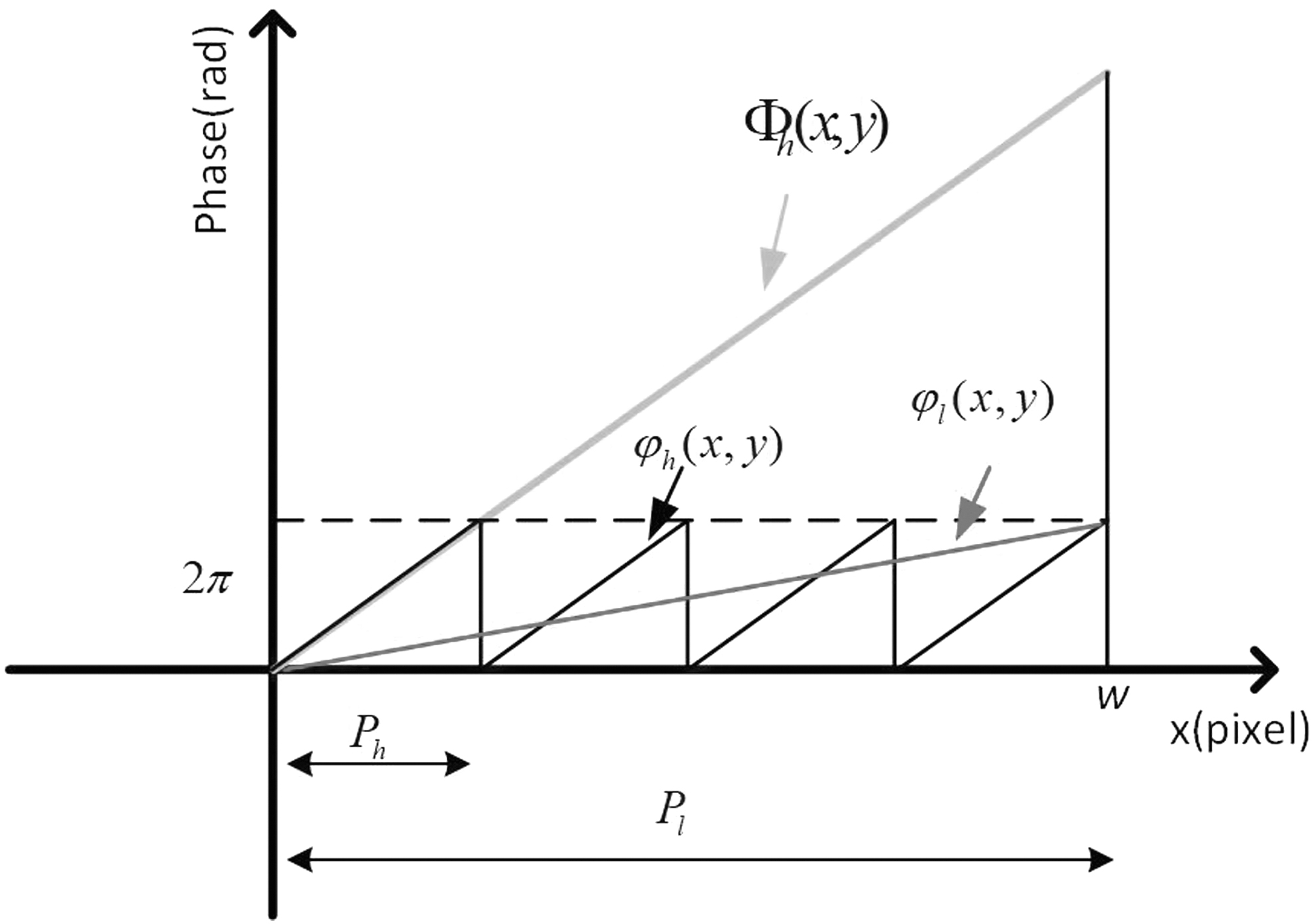
Principle diagram of multifrequency method. The red line segment represents the low-frequency continuous phase, and the black line segment represents the high-frequency wrapped phase. The high fringe frequency continuous phase (green line segment) can be obtained from Formula (3–5).
Orthogonal grating projection
The phase shift contouring of orthogonal grating projection can calculate both horizontal and vertical phase information by one measurement, similar to the principle of orthogonal grating projection. In this study, the sinusoidal components of two frequencies are encoded into one fringe pattern, but the fringes of the encoded two frequencies are not orthogonal. The encoded two frequencies satisfy f1<f2; a discussion of these two frequency constraint relationships is presented at the end of this section. And the light intensity distribution function of each pixel position of the fringe pattern has:
Where there are five unknowns in equation (6), and at least five plots are needed to solve the phase, that is, M ≥ 5. To realize a fast phase solution, M = 5 is taken in this article.
(4) Fast Multifrequency Phase Unwrapping Method
The standard four-step phase-shifted sinusoidal fringes are used to obtain the highest fringe frequency phase to ensure the phase accuracy, and then the remaining five fringes are used to obtain the phases of the other two frequencies. In other words, the sinusoidal fringes are used to obtain the wrapped phase of the high fringe frequency
Using equation (2), we can get the wrapped phase
From equation (5), the successive phases
The f1, f2, f3 constraint relationship is discussed as follows: from the requirements of the multifrequency method described above, it can be seen that only f1 = 1, one cycle of the stripe pattern at this frequency can cover the whole object under test. Furthermore, we introduce the phase error for discussion. For ease of description, the following expression omits pixels (x, y).
Assuming that
Where:
Then:
Bringing equation (17) into the stripe level equation (12), we obtain:
From equation (18), if we want to get the correct k2, we need to satisfy that
Experimental Analysis
Accuracy verification experiment
To test the reconstruction accuracy of the algorithm in this study, the standard sphere of matte surface ceramic is reconstructed and compared with the traditional multifrequency algorithm. The experimental results of the traditional multifrequency algorithm are shown in Figure 5, and the experimental results of the algorithm in this study are shown in Figure 6. From the above results, it can be seen that the algorithm in this study can correctly solve the phase to get the continuous phase and only nine projection images are needed, and the image projection efficiency is improved by 25% compared with the traditional algorithm.
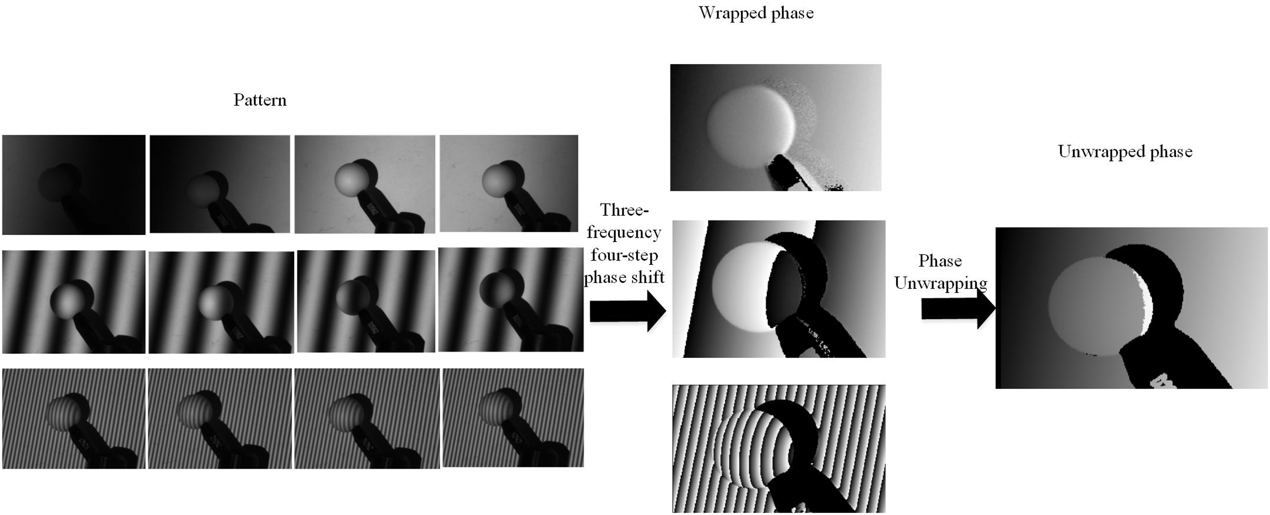
Experimental results of traditional multifrequency algorithm. The algorithm collects 12 deformed phase-shifting fringes modulated by the object through the camera, obtains the wrapped phase map through the traditional three-frequency four-step algorithm, and then obtains the final continuous phase map through the multifrequency phase unwrapping method.
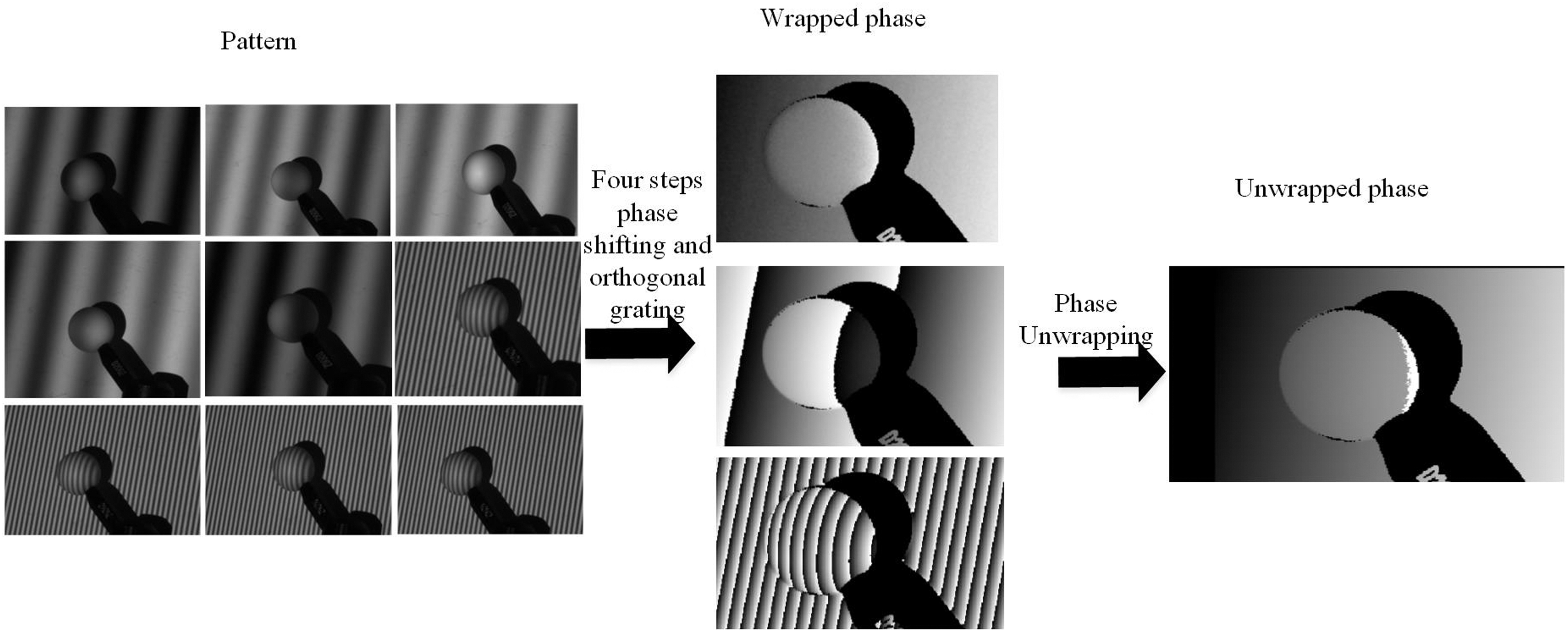
Experimental results of the algorithm in this study. The algorithm collects nine deformed phase-shifted fringes modulated by the object through the camera and uses four-step phase-shifted sinusoidal fringes to obtain the highest fringe frequency wrapped phase, thus ensuring the accuracy of the phase. The remaining two wrapped phase maps are obtained by combining the orthogonal grating projection algorithm, and the final continuous phase map is obtained by the multifrequency phase unwrapping method.
From the principle of multifrequency method, it is known that the fringe pattern with the lowest fringe frequency can cover the whole measured object in one cycle, and the phase of the fringe pattern at that fringe frequency does not need to be phase unwrapped, and its truncated phase is equal to the continuous phase. Therefore, fringe frequency 1 is chosen as its lowest fringe frequency. The selection of fringe frequencies usually also follows a multiplicative relationship to complement each other in the phase unwrapping process. Based on the above conditions and to verify the consistency of the experimental results, we performed 14 sets of 3D fitted spherical experiments on a standard sphere of matte surface ceramic with an actual diameter of 20.0185 mm and a roundness of 0.0020 mm by continuously varying the value of the highest fringe frequency.
The standard sphere was reconstructed using the algorithm of this study and the traditional multifrequency method, respectively. The Geomagic Studio 12 software processed the point cloud data obtained after the reconstruction and fitted the sphere, and the two methods were fitted to the standard sphere diameter change shown in Figure 7, from which it can be seen that the algorithm of this study has high reconstruction accuracy and is close to the traditional multifrequency algorithm. At the same time, the principle of Nyquist sampling theorem needs to be considered when choosing the fringe frequency, and by choosing a sufficiently high fringe frequency, the details of the phase change can be accurately captured to improve the accuracy and precision of phase unwrapping and ensure the integrity and reliability of the phase information.
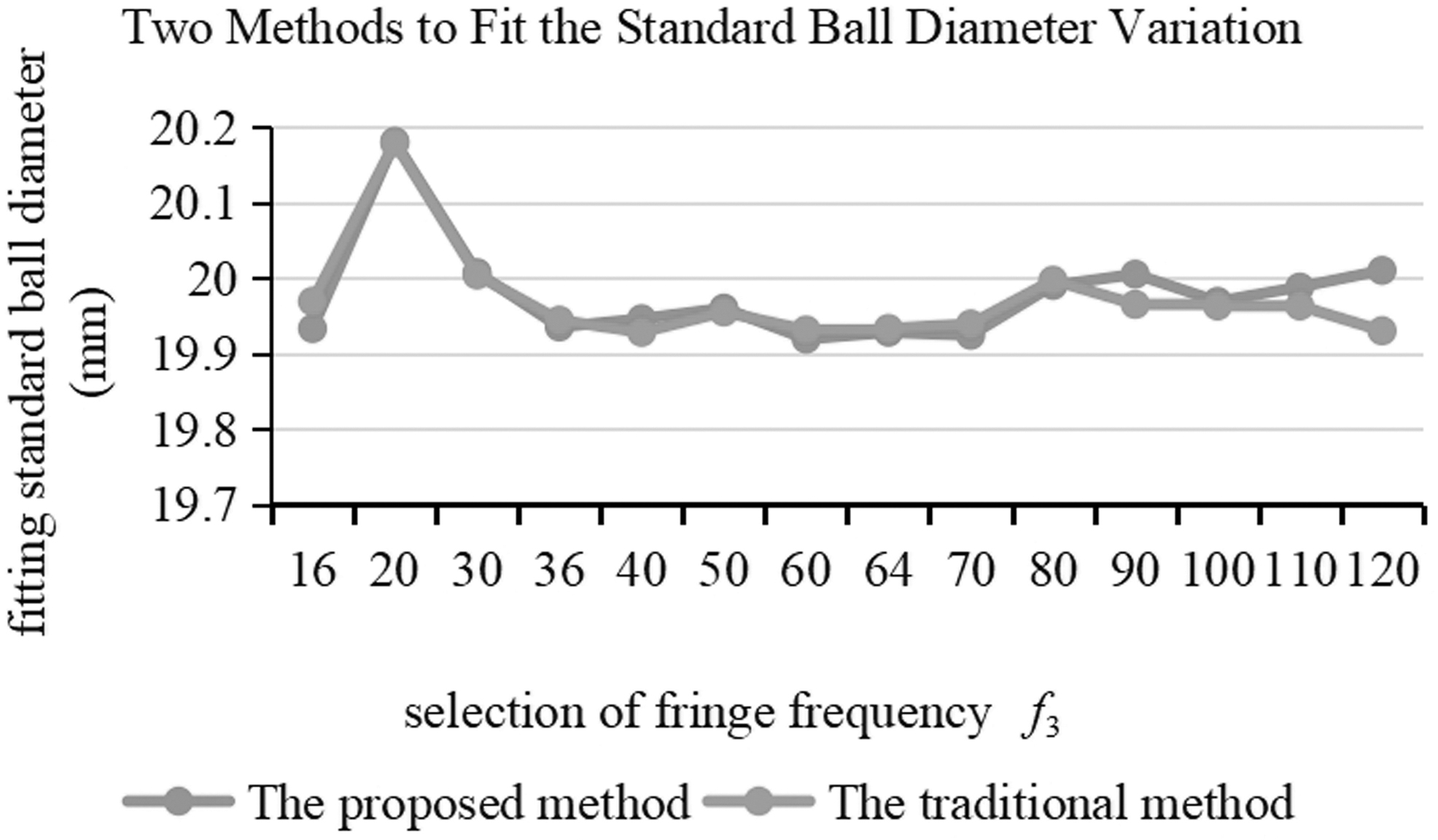
Two methods to fit the standard ball diameter variation. By arbitrarily selecting 14 groups of the highest frequency f3 values (abscissa), the traditional method and the method in this article are used to reconstruct, respectively. Geomagic Studio 12 software is used to perform standard ball fitting on the generated point cloud image, and the reconstruction accuracy of the two methods is judged by the standard ball diameter (ordinate) obtained by fitting.
Complex object reconstruction experiment
With the popularity of blind boxes, various doll customizations have followed. To follow the trend of the times and cater to people's preferences, 3D printed objects have become more complex and diverse. To evaluate the effectiveness of this algorithm in terms of complex object reconstruction, we chose a blind box doll with a complex surface for reconstruction experiments.
The doll is made of polyvinyl chloride, a vinyl polymer, which is widely used because of its high plasticity and low cost. The material has nonflammability, high strength, resistance to climate change, and excellent geometric stability and is highly resistant to oxidizers, reducing agents, and strong acids.
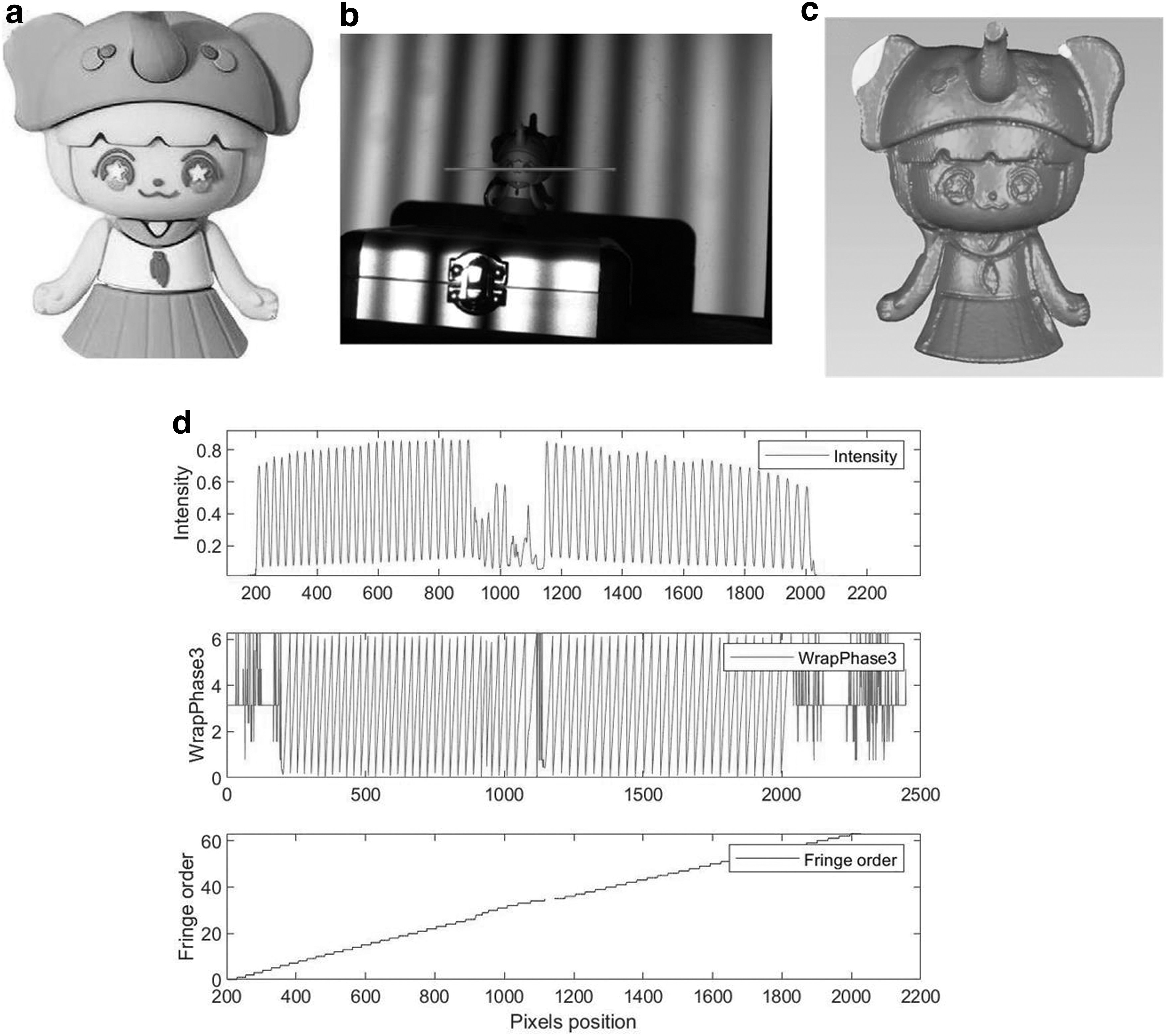
From the accuracy verification experiments in the previous section, it can be obtained that the higher the accuracy and precision of choosing a sufficiently high fringe frequency phase unwrapping, the highest fringe frequency f3 is chosen here for the experiment at 120. The Red, Green, Blue image of the doll is shown in Figure 8a, the fringe image modulated by the doll to be tested is shown in Figure 8b, the complex contour underlined in red, and the Intensity, Wrap Phase, and Fringe Order underlined are shown in Figure 8d. The final reconstruction result of the doll is shown in Figure 8c, and its contour is complete and the surface is smooth, with good reconstruction effect.
Reconstruction of doll.
Plaster model reconstruction experiment
Gypsum material is widely used in 3D printing, its chemical nature is calcium sulfate, compared with other 3D printing materials, gypsum has the following advantages: fine granular powder, particle diameter is easy to adjust; relatively low price, cost-effective; safe and environmentally friendly, nontoxic and nonhazardous; the material itself is white, printing models can be achieved in, supporting full-printing. The plaster stent made by 3D printing can be individually designed for each patient by 3D scanning according to the severity of the injury. Based on the above application, the model of plaster material is selected here for 3D reconstruction to provide a digital model for 3D printing.
The lowest fringe frequency f1 = 1, the middle fringe frequency f2 = 12, and the highest fringe frequency f3 = 120 are chosen here for the experiment. Figure 9a–c shows the low, middle, and high fringe frequency wrapping surfaces, respectively, and Figure 9d is the high fringe frequency unwrapping phase diagram. Figure 9e and f is the reconstructed surface of the plaster model, and (f) is the enlarged part of (e). The measured plaster model is shown in Figure 9g. The final obtained reconstruction result of the plaster model is shown in Figure 9h, which has a complete contour and smooth surface, with good reconstruction effect.
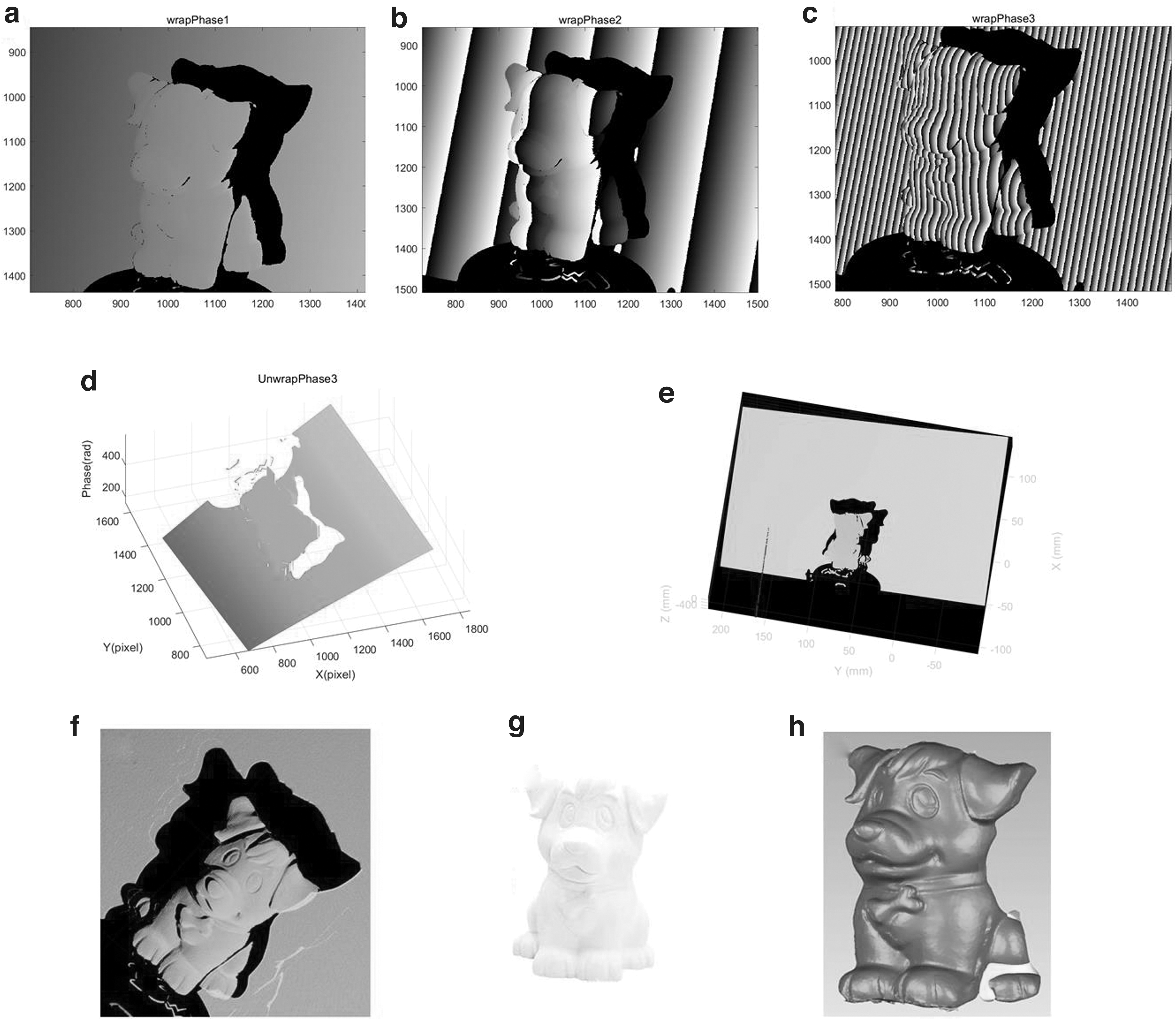
Gypsum model reconstruction.
Conclusion
This study proposes a fast multifrequency phase unwrapping method based on 3D printing object appearance acquisition and describes the basic principle of the method in detail. The method in this study uses a standard four-step phase-shifted sinusoidal fringe to obtain the highest fringe frequency wrapped phase, which ensures the phase accuracy. Similar to the method of encoding fringes by orthogonal gratings, two fringes are encoded into five fringes with different amplitude, fringe frequency, and phase shift. The difference is that the two fringes are not orthogonal. Then the fringe order can be obtained using the multifrequency method, and the phase of the highest fringe frequency is expanded.
In this process, the background intensity and modulation intensity are not used to recover the phase, so the method is not easily affected by the ambient light and has high robustness. Experimental results verify that under the same experimental conditions, the algorithm in this study has a similar accuracy as the conventional multifrequency algorithm and maintains the advantages of the multifrequency method for independent pixel computation, but the required projection patterns are reduced from 12 to 9, and the projected fringe patterns are fewer and projection speed is faster.
Discussion and Future Perspectives
In this study, we reveal the relationship between 3D printing and accurate measurement by introducing a multifrequency phase expansion method to restore the external details of complex objects to improve the quality and accuracy of 3D printed manufacturing. In addition to improving the quality of the projected stripes or the camera and projector calibration accuracy, users can also improve the reconstruction accuracy by selecting the appropriate acquisition object material. However, this preliminary study has some limitations for further improvement:
First of all, we performed some experiments to verify the accuracy of the method. However, we did not obtain the optimal background light intensity and tuning system, and future work can focus on determining the optimal background light intensity and tuning system to find the optimal combination of parameters by comparing experiments to achieve the best measurement performance.
In addition, the method relies on a noncontact optical measurement technique and therefore may be challenging for materials with low reflectivity or nonuniform reflective properties, such as black or highly reflective surfaces. In these cases, other auxiliary measurement techniques or preprocessing methods may be required to overcome these limitations.
Finally, to address the above existing limitations, we will further improve the phase unfolding algorithm at a later stage to enhance its performance and adaptability to handle more complex and detail-rich external features.
Footnotes
Acknowledgments
The authors wish to express their appreciation to their family and friends for their understanding, encouragement, and support.
Authors' Contributions
X.Z.: Conceptualization (lead); writing–original draft (lead); formal analysis (lead); writing–review and editing (equal). Y.W.: review and editing (equal). G.D.: Software (lead); writing–review and editing (equal). S.Y.: Conceptualization (supporting); Writing–original draft (supporting); Writing–review and editing (equal).
Author Disclosure Statement
No competing financial interests exist.
Funding Information
This work was financially supported by the National Natural Science Foundation of China (62003292).