
Abstract
Cutting tools with orderly arranged diamond grits using additive manufacturing show better sharpness and longer service life than traditional diamond tools. A retractable needle jig with vacuum negative pressure was used to absorb and place grits in an orderly arranged manner. However, needle hole wear after a long service time could not promise complete grit adsorption forever. This article proposed an improved YOLOv5s to detect the adsorption status of diamond grits on pinholes to maintain the planting rate of diamond grits in each matrix during the additive manufacturing process. First, the added detection head extracts higher level semantic information. Second, depthwise separable convolution + batch normalization + sigmoid linear unit modules containing depthwise separable convolutions (DSC) are used instead of convolution + batch normalization + sigmoid linear unit to reduce the number of parameters. Introducing DSC into the Bottleneck1 module results in faster computational speed than introducing bottleneck. Finally, coordinate attention is added at appropriate locations to improve detection accuracy. The improved YOLOv5s achieves an average 19.6% reduction in both parameters and floating point operations per second. The inspection system performance was validated by collecting data on a large number of vacancies and worn vacancy pinholes. Compared with the original YOLOv5s, the detection time for a layer of diamond grits with the system based on the improved YOLOv5s model decreased from 6.35 to 5.06 ms, and the detection accuracy was higher than 98%. When the absorption rate was detected below 95%, a redo command was given. The equipment has been in continuous operation for 1 year, and the vacancy rate of diamond grits in the orderly arranged diamond green segment produced by this additive manufacturing equipment is less than 5%.
Introduction
Diamond cutting tools have been widely used in the precision machining of hard materials owing to their outstanding performance. 1 Generally, diamond grits are mixed mechanically with alloy powders composed of iron, copper, cobalt, nickel, and tin for manufacturing diamond cutting tools. This leads to the random distribution of diamond grits in the matrix, consequently resulting in lower cutting efficiency and shorter service life under conditions of high-speed cutting. 2 A suitable diamond grit interval makes the diamond grits wear evenly and leaves an exit space for cutting debris. This is helpful for improving the diamond grit utilization rate and prolonging the diamond tool service life. Koshy et al. 3 conceived a diamond grinding wheel model with an ordered arrangement of diamond grits on the wheel surface and found by computer simulation that the wheel abrasive performance could be improved significantly.
Inspired by the single layer with orderly arranged diamond grits, Shinhan Diamond Industry Co., Ltd. developed automatic cold pressing equipment (Automatic array system, ARIX) to orderly place diamond grits in multilayers, 4 as shown in Figure 1. The diamond tool with segments manufactured via ARIX showed both high sharpness and long service life. Unfortunately, ARIX only produced 50,000 pcs of green segments with a 3D lattice of diamond grits per month. In 2012, Xu 5 invented a new type of additive manufacturing equipment with a rotary working platform, namely, AME001, to fabricate green segments with orderly arranged diamond grits layer by layer.
Schematic of blade segment with a 3D diamond grit lattice.
In AME001, a retractable needle jig with vacuum negative pressure was designed to absorb and place diamond grits in an orderly manner, as seen in Figure 2. However, it is difficult to guarantee the diamond grit absorbing rate due to slippery factors for negative absorbing forces, such as needle jig abrasion, irregular diamond grit shapes, and vacuum negative pressure fluctuation.
Schematic of the retractable needle jig for absorbing.
Machine vision has been used to automatically measure geometric dimensions, textures, and colors of products, and provides innovative solutions in industrial automation owing to its high efficiency and high precision. Lins et al. 6 applied machine vision to inspect a tool's wear level during processing. Pajares et al. 7 applied a machine vision system in agricultural autonomous vehicles, which can effectively identify weeds in corn fields. In the field of additive manufacturing, the research and application of nondestructive testing technologies to identify defects are becoming increasingly urgent. 8 Acoustic monitoring and machine vision are commonly used for defect detection. Ramalho et al. 9 analyzed the acoustic signals in wire and arc additive manufacturing using the time and frequency domain techniques, and signatures obtained were used to pinpoint the location of flaw formation.
To detect flaw in the wire-based directed energy deposition process, Bevans et al. 10 extracted a single feature called graph Laplacian Fiedler number from the noise-contaminated acoustic sensor data, which is subsequently tracked in a statistical control chart. Nascimento et al. 11 proposed a novel methodology with AI-based computer vision to achieve color analysis, shape analysis, and positioning of defects in additive manufacturing parts. Charalampous et al. 12 introduced a vision-based method to scan, filter, segment, and correlate in real time the physical printed part with the digital 3D model as well as to evaluate the performance of the additive manufacturing process.
Additive manufacturing process has been introduced to form a three-dimensional diamond tool layer by layer, 13 however, the quality control of orderly arranged diamond grits poses a noteworthy challenge. Based on the mechanical structure of AME001, Chen et al. 14 developed an online machine vision inspection system with a machine learning algorithm to reduce the vacancy rate of absorbing diamond grits. An image acquisition device was fixed under the needle jig to acquire images of the diamond grit absorption status. To ensure the absorption rate of the diamond grits in the needle jig, the adsorption process was reexecuted until the vacancy rate of the diamond grits inspected by machine vision reached the standard value. The inspection accuracy with the machine learning algorithm could be as high as 98%. In the early stage of equipment operation, the filling rate of diamond grits can reach 95%.
Unfortunately, the needle jig shown in Figure 2 is constantly worn during the working process, and the badly worn pinholes often cannot absorb diamond grits. Since there is no obvious difference in appearance between badly worn pinholes and filled pinholes, the rate of false detection with the machine learning algorithm increased over time. After 6 months of operation, the filling rate of the diamond grits was less than 90%.
Deep learning is widely used in tasks such as image recognition, natural language processing, and speech recognition because of its ability to automatically extract complex features (including spatial, scale, and temporal features) from raw data. The principle of using transfer learning in deep learning is to make full use of prior knowledge in various industries to fine-tune pretrained models and improve the model's ability to capture nonlinear information from data sets, which can simplify feature engineering to save time and resources. Nowadays, deep learning is the most effective, time- and cost-efficient machine learning approach. 15 Based on machine vision with a deep learning algorithm, Yun et al. 16 developed an automated optical inspection (AOI) system for detecting metal surface defects to solve the problem of data imbalance, augmentation of images. Through learning the distribution of the given data with an improved variational autoencoder method, its accuracy increased from 96.27% to 99.69%.
Sicard et al. 17 provided a special method for characterizing diamond grit through automatic semantic segmentation with a data-driven deep learning model. Yuting and Hongxing 18 proposed the improved YOLOv4-tiny model (YOLO-SPI) for detecting the dislocation of the cylindrical silicon growth process and achieved good performance in detecting single-crystal silicon dislocation. Compared with machine learning algorithms, deep learning algorithms for image processing have been shown more robust in machine vision inspection. 19 Two-stage detectors have been the dominant approach in object detection for a long time and are mostly represented by the RCNN family. 20 In contrast to two-stage detectors, one-stage detectors predict both bounding boxes and object categories. Although the first-stage detector has an obvious speed advantage, its precision is lower. The most representative models for single-stage detectors are the YOLO family, 21 single-stage detector, 22 and RetinaNet. 23
The YOLO algorithm can take advantage of its excellent speed while ensuring accuracy, which is of great significance to lightweight detection in the industrial field.
To improve the accuracy and speed of YOLOv5s for detecting vacancy pinholes, we modified the original network structure by deepening the feature map extraction, reducing the convolutional operation volume, and adding attention. The main contributions of our proposed method are as follows:
The added detection head can extract higher level semantic information. Depthwise separable convolution + batch normalization + sigmoid linear unit (DSCBS) modules containing depthwise separable convolutions (DSC) are used instead of convolution + batch normalization + sigmoid linear unit (CBS) to reduce the number of parameters. Introducing DSC into the Bottleneck1 module results in faster computational speed than introducing the bottleneck. Coordinate attention (CA) is added at appropriate locations to improve detection accuracy. Precise positioning is achieved by using the location point mapping algorithm.
Vision Inspection System and Data Sets
System architecture
Detecting diamond filling in pinholes based on machine vision consists of two parts: image acquisition and defect detection. Image acquisition comprises auxiliary machinery, light sources, intelligent industrial cameras, and optical lenses. The defect detection unit determines whether an image is defective and the defect severity. 24 The defect detection results are output to an actuator to control and reject defective products.
The auxiliary machinery
According to the mechanical structure of the diamond grit orderly arrangement device in AME100, auxiliary machinery for acquiring images is developed. As shown in Figure 3, the camera with the looking up lens is fixed under the feed slideway to photograph the needle jig. The negative pressure of needle jig is set to −30 kPa by vacuum pump, after the diamond grits are absorbed by the needle jig, the skip car moves away, and the camera quickly photographs the needle jig with absorbed diamond grits. Only when the adsorption rate is higher than the default value does the needle jig move to the powder mold and plant the diamond grits in the metal matrix in a certain format by canceling the vacuum negative pressure. The image acquisition device is shown in Figure 4. The transparent glass is sealed at the top of it to protect the camera lens.
Image acquisition schematic.
Sealing device.
Camera and lens
For machine vision inspection systems, both charge-coupled device (CCD) chips and complementary metal-oxide-semiconductor (CMOS) chips can convert light into electrical signals. CCD cameras have the characteristics of high sensitivity, low noise, and fast response. Generally, CMOS camera image quality is inferior to that of CCD cameras in the same environment. However, the CCD camera takes much more time to acquire the image and is more expensive. To adapt to the efficiency of AME101, a camera with a planar CMOS image sensor is selected for image acquisition. Through compensation with a unique lighting system, both the accuracy and shutter speeds can be satisfied by using a BASLER brand CMOS color industrial camera with 5 megapixels and a KOWA LM25JC5M5 high-definition lens. The imaging field of view is ∼62 × 44 mm. Its resolution is 2854 × 1942, and the pixel accuracy can reach 0.02 mm.
Lighting source
The lighting source plays the roles of illumination, weakening the chaos and amplifying image features and defects. In AME101 with a deep learning algorithm, the manufacturing process is usually carried out in an enclosed space to prevent metal powder from polluting the light source. Meanwhile, diamond grit, which is monocrystalline, always results in special reflective phenomena due to its characteristic of anisotropy. It is often misjudged as a vacancy when an ordinary flat panel light source is used. To optimize the scattered light-emitting diode (LED) light, two white strip LED light sources are symmetrically set at 60° to illuminate the needle jig, as shown in Figure 5.
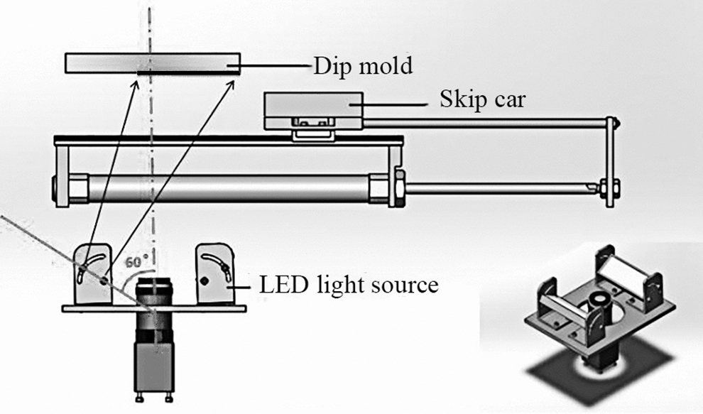
The lighting source: lighting source schematic.
Under this lighting system with the advantages of good orientation and longevity, the image brightness of the image area is uniform and moderate, and the boundary between the pinhole position area and the background is clear, as shown in Figure 6.
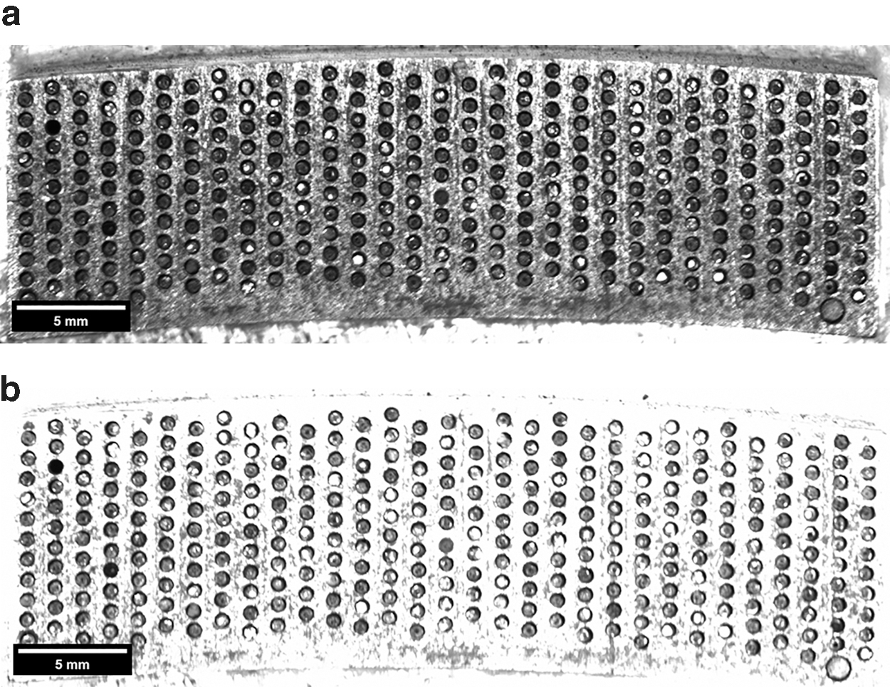
Contrast of the imaging effect of lighting sources at different angles.
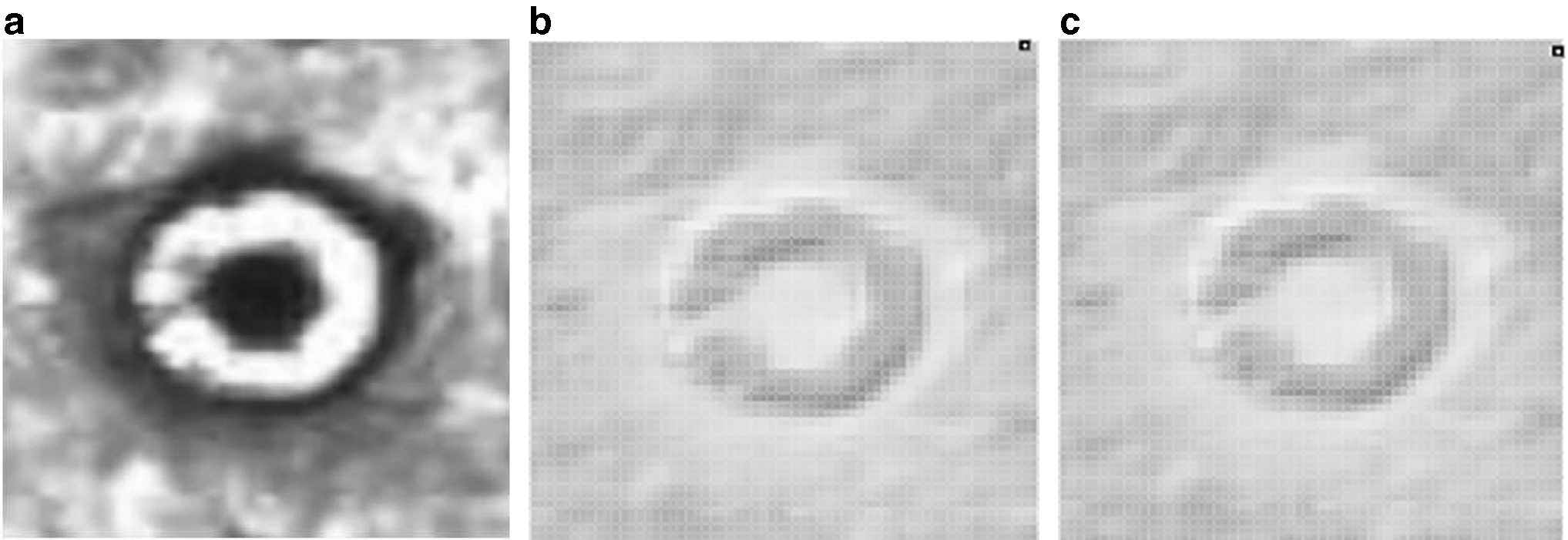
The type of image to be detected
There are several kinds of images detected in this research: pinhole with adsorbed diamond grit (filled pinhole), pinhole without adsorbed diamond grit (vacancy pinhole), and badly worn pinhole without adsorbed diamond grit (badly worn vacancy pinhole). In particular, there is no apparent difference in appearance between the badly worn vacancy pinhole and the filled pinhole. As shown in Figure 7, this type of vacant pinhole gradually appears during the production process, and it is difficult to detect using traditional machine vision algorithms due to the variable shape and strong randomness.
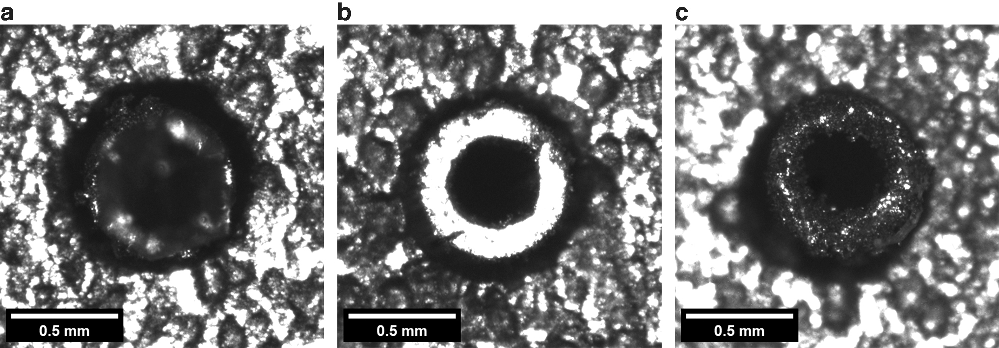
Different kinds of pinhole images.
Data augmentation
The data collected in actual production lines are limited, the number of pinhole defect pictures is expanded through geometric transformation, and white noise is added to some images to simulate the dust environment in the production process of diamonds arranged in an orderly manner. Some data set images are shown in Figure 8.
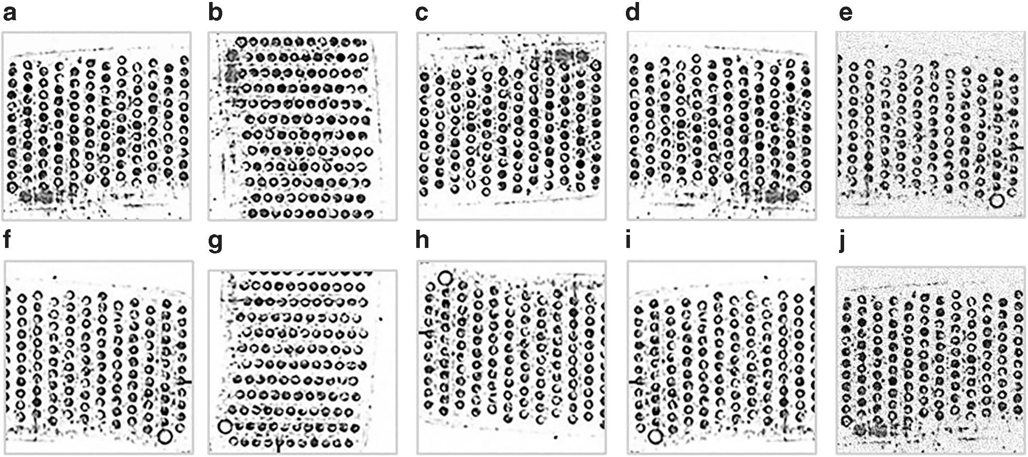
Several ways to expand the data set.
The Proposed Method
A vision inspection approach for blade segments with orderly arrangements of diamond grits based on improved YOLOv5s is proposed. The research aims to balance computing cost and detection accuracy, achieving lightweight and high-accuracy detection. Specifically, it can still show strong robustness in detecting vacant pinholes in the case of pinhole wear.
Related work
This section introduces the related neural network model and algorithms on which our proposed method is based, which include YOLO,25,26 depthwise separable convolution (DSC),27,28 and coordinate attention (CA). 29 In addition, coordinate position conversion of the acquired image is realized by using the principle of location point mapping, which can assist in positioning.
YOLOv5s
The YOLOv5 series is a single-stage target detection algorithm that has demonstrated excellent performance and has been applied in a wide range of fields. 30 The network architecture consists of a backbone network, neck, and a detection head, as shown in Figure 9. The backbone network is based on the cross-stage partial network and consists of a series of convolutional layers. The model neck is mainly used to generate feature pyramids, which help the model generalize well on object scaling and identify the same object with different sizes and scales. The detection head consists of three convolutional layers and predicts bounding boxes and class probabilities for each anchor box. The YOLOv5 series consists of four versions: s, m, l, and x.
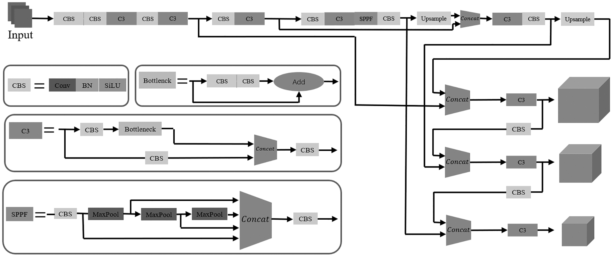
The architecture of the YOLOv5s network. 31
These versions differ in the scaling factor of network width and depth. They have different controls on “width_multiple” and “depth_multiple.” Among them, YOLOv5s has a depth of 1, which means that there are no repeated modules. Therefore, the width of its feature map is also the smallest among the several models. This makes the accuracy of the YOLOv5s slightly inferior to other similar models, but it has a higher speed.
As a lightweight network of the YOLO series, YOLOv5s is more suitable for applications with limited computing resources and performs best, especially on industrial computers, whose performance is generally not at the highest level.
Depthwise separable convolution
Compared with the traditional convolution network, depthwise separable convolution (DSC) can reduce the number of calculations since DSC decomposes the convolution into two separate calculations: depth convolution and point-by-point convolution. As shown in Figure 10, assume the size of the input characteristic graph is Dk × Dk × M, the size of the convolution kernel is DF × DF × M, and its number is N. Assuming that each point in the spatial position of the corresponding feature map undergoes a convolution operation, then, it can be seen that a single convolution needs to be calculated Dk × Dk × DF × DF × M × N times. This is because the spatial dimension of the characteristic graph contains Dk × Dk points, and the number of calculations of the convolution operation for each point is consistent with the size of the convolution kernel DF × DF × M.
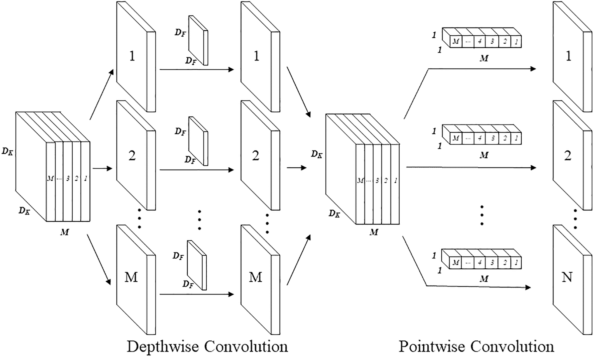
The process of depthwise separable convolution.
Therefore, the total number of calculations for a single convolution is Dk × Dk × DF × DF × M, and the total number of calculations for N convolution is Dk × Dk × DF × DF × M × N.
A similar analysis of DSC showed that the total number of calculations with depthwise convolution is Dk × Dk × DF × DF × M, while the total number of pointwise convolution calculations is Dk × Dk × M × N. Therefore, the total number of DSC calculations is Dk × Dk × DF × DF × M + Dk × Dk × M × N. Compared with the ordinary convolution, the ratio of DSC calculations to ordinary convolution is N−−1 + (DF)−2. Hence, the DSC can greatly reduce the number of calculations compared with the traditional standard convolution.
Coordinate attention
Humans can naturally and effectively find salient regions in complex scenes. 29 Inspired by the human visual system, attention mechanisms were introduced into computer vision to mimic this aspect of human perception. Such an attention mechanism can be viewed as a dynamic weight adjustment process based on features of the input image. Hou et al. 31 proposed coordinate attention, which enables the network to focus more on the target location information and use a small cost to dedicate to a larger area.
Defect detection architecture
Increase the number of network detection heads
Small-target detection has long been a difficult point in target detection. It aims to accurately detect small targets with very few visual features in the image (targets below 32 pixels × 32 pixels). The diameter of the pinhole that adsorbs diamond grits is only 0.75 mm, which is lower than the standard for small-target detection pixel size (Fig. 11).
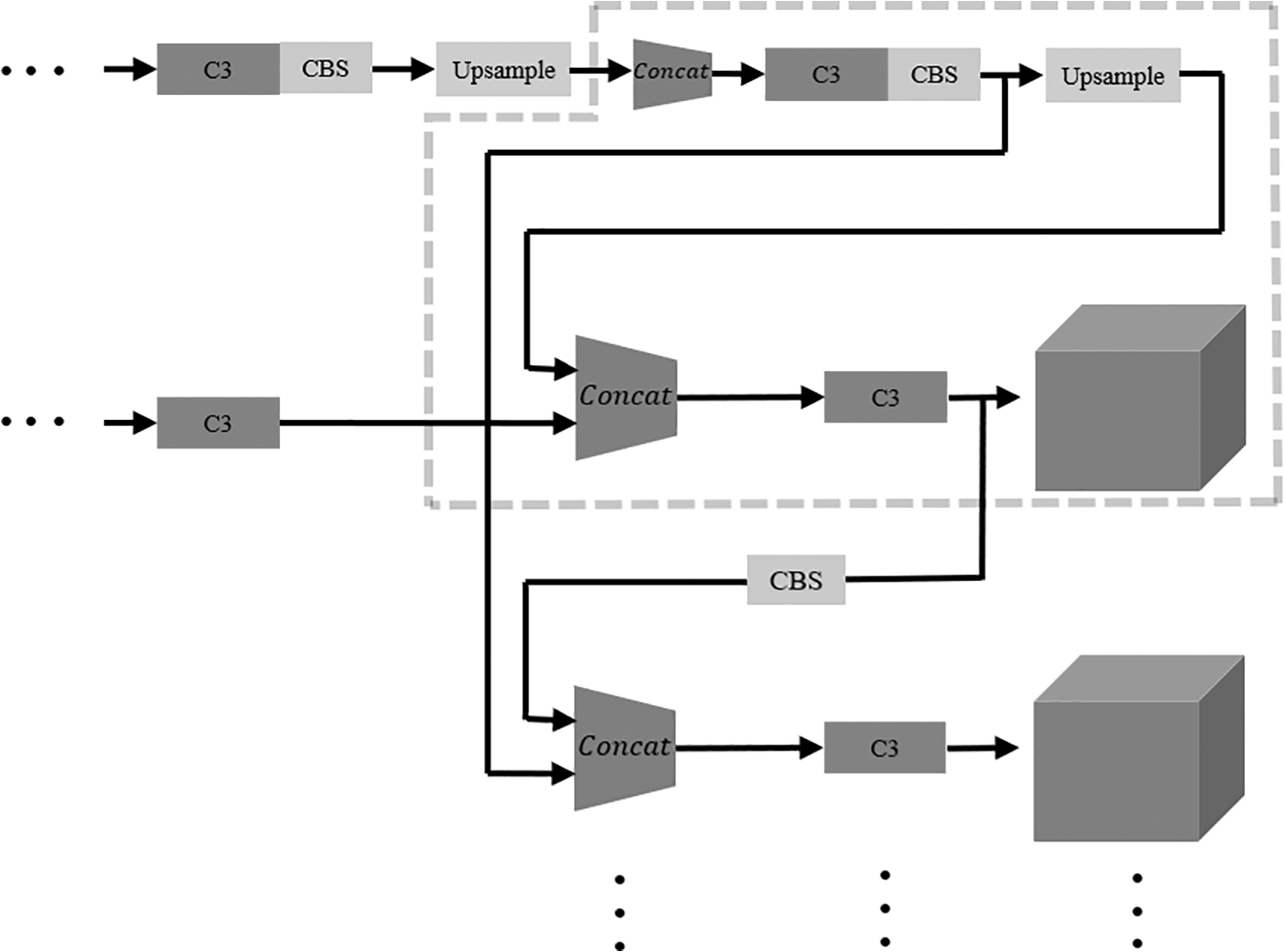
Additional detection heads (partial view).
After two rounds of upsampling, a set of depth-separable convolutions are added to extract features while reducing the number of computations. After three rounds of upsampling, feature maps with different sizes are generated and input into a feature pyramid. The number of layers in the neck's feature pyramid is increased by one layer, and the new layer's feature maps are input into the head. The four-head structure can reduce the negative impact of equipment vibration on the pinhole image acquisition scale. High-resolution feature maps generated by multiple up samples are more sensitive to tiny objects.
Introducing DSC
To reduce the number of CBS and the bottleneck calculations, we design a DSCBS unit to replace the original CBS unit. The depthwise separable convolution operation is also performed on the dual CBS modules in the bottleneck module, and a lightweight Bottleneck1 unit is designed. As shown in Figure 12, taking the input of 3 × 640 × 640 as an example, after 64 convolution kernels of 3 × 3 size are processed, the number of calculations can be reduced by 87.3% by using DSC. The use of DSC operations ensures that features can still be accurately extracted, as shown in Figure 13.
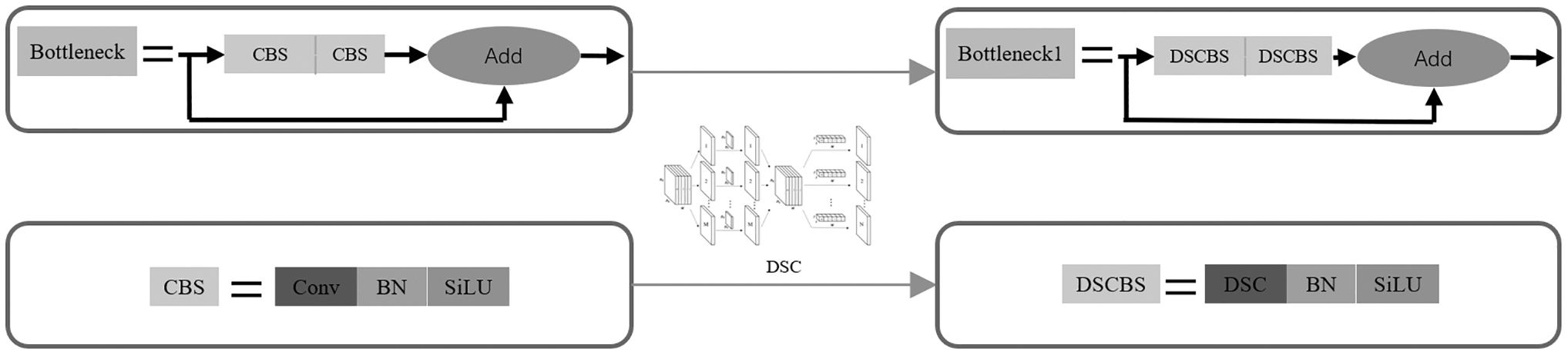
Design modules with depthwise separable convolutions.
Convolution effect comparison.
Coordinated attention
By inserting the coordinate attention (CA) module into different positions of the backbone network to complete the ablation experiment and selecting a relatively optimal scheme, the backbone network can be divided into three different stages: front, middle, and back (Fig. 14).
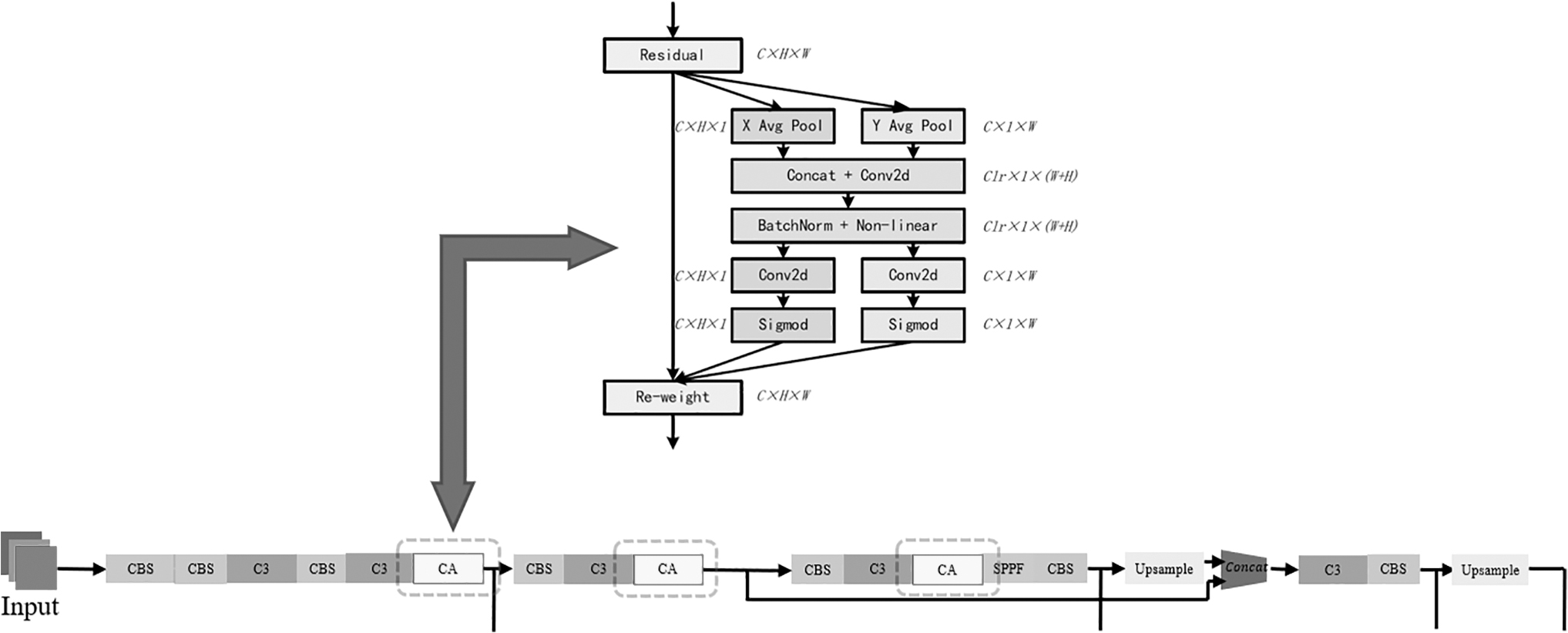
Add CA modules in different locations. CA, coordinate attention.
The CA modules are inserted at the end of different stages. Compared with the original version of the network, several sets of data were obtained for the mean average precision (mAP) indicator. As shown in Table 1, the experiments demonstrated that the CA module has better performance in the early stage of the backbone network and can better guide the direction of feature extraction in the initial process of feature extraction (Fig. 15).
Thermal diagram of the feature map after adding CA.
Ablation Experiments of Different Insertion Positions of the Coordinate Attention Module
mAP, mean average precision.
Using Grad-CAM as a visualization tool to generate a thermal feature map, it can be seen in the figure that the model with the CA module can focus more on the region of interest during the feature extraction process.
Location point mapping
The precise positioning algorithm of pinholes is a pretreating procedure for feature extraction and an essential prerequisite for accurate detection. The innovation of the pinhole position algorithm lies in that it can determine the coordinate of the pinhole with a diameter of only 0.75 mm. It can be divided into two parts: holistic correction of the pinhole position and individual fine-tuning of the pinhole position.
Before detecting the collected images, the system will automatically import a new hole coordinate file and generate the hole's feature extraction area based on new coordinates. However, due to needle jig wear or mechanical vibration, there are some positional differences between the area generated by the new coordinates and the hole to be detected, and so, the coordinates of the holes need to be corrected holistically. For holistic correction of the pinhole position, choose the upper-left and lower-right corner points, and use threshold segmentation to finds location points. The coordinate file is input into the database to facilitate the rapid acquisition of information by the machine vision inspection system. Then, coordinate position conversion of the acquired image is realized by using the principle of location point mapping. The principle is shown in Figure 16.
Schematic diagram of location point mapping.
As shown in Figure 17, each image has two location points and a positioning line. The holistic correction algorithm calculates the distance between the reference image positioning point and the measured image positioning point, the coordinate scaling ratio and the angle between the coordinate and the image. The holistic correction algorithm compares the coordinate scaling ratio, the distance and the angle of the two location points between the measured image and the standard reference. Through the two-dimensional transformation of the coordinate position according to the order of translation, scaling and rotation, two positioning lines and the coordinate position coincide with the center of the image hole location area.
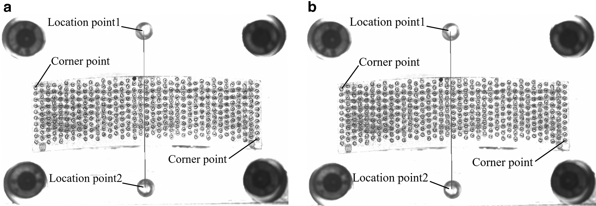
The photograph effect after holistic correction.
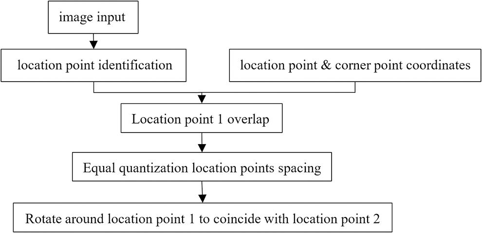
Since the coordinates of the pinhole are derived from the drawings of the stamping tool, and the individual hole positions of the actual stamping tool are deviated from the coordinate on the drawings, the positioning point coordinate mapping cannot solve the problem of individual position deviation. An individual fine-tuning algorithm was developed to obtain actual coordinates. The principle of the individual fine-tuning algorithm is shown in Figure 18.
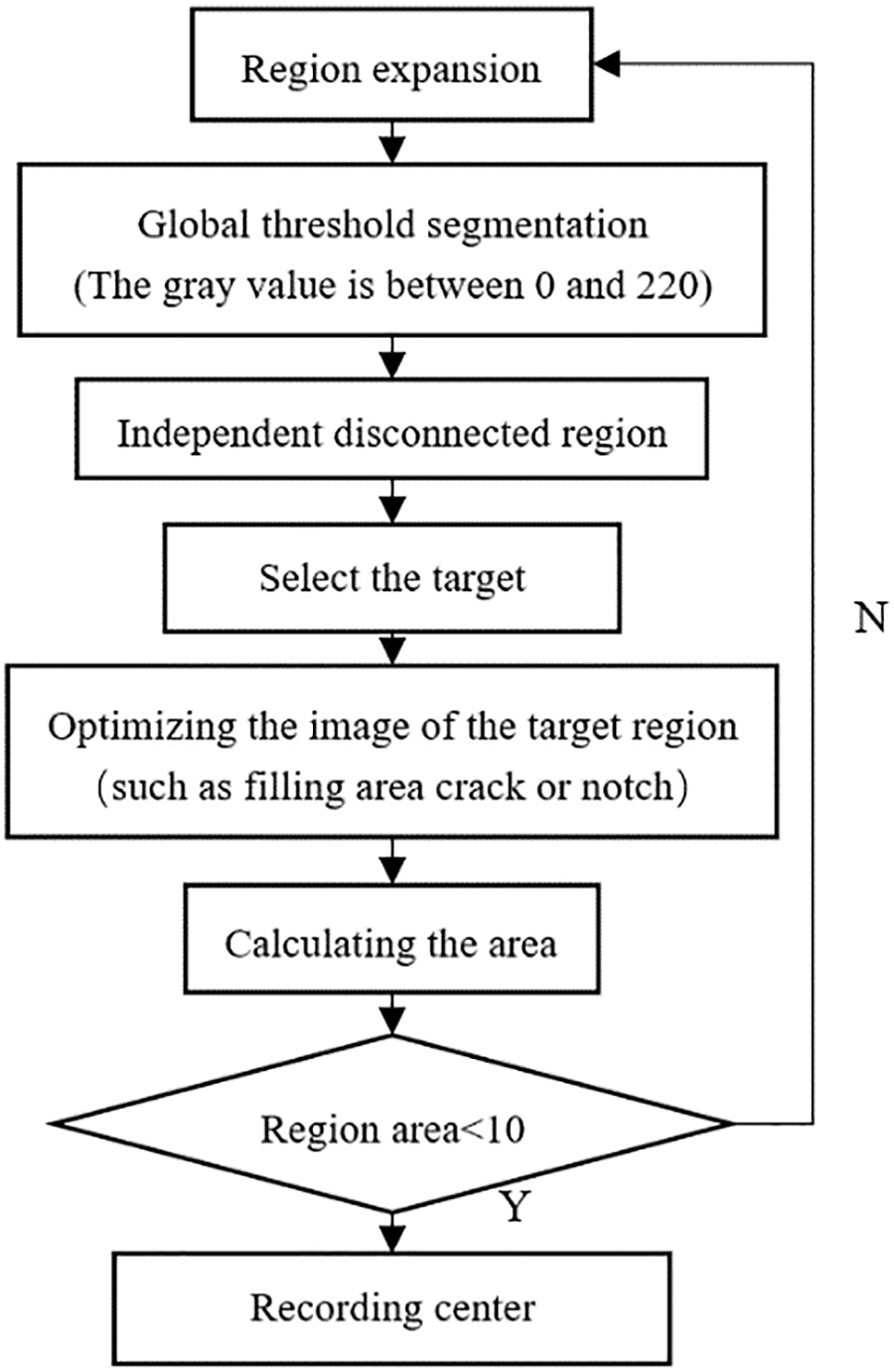
Flowchart of the individual fine-tuning algorithm.
Referring to the boundary tracking method, the acquired image is scanned from the upper-left corner to the lower-right corner and separated by using threshold segmentation to obtain the actual position of the needle jig area. Specifically, each pinhole image is separated, and its center coordinate is calculated. Then, affine transformation is performed to the center coordinate position of the pinholes to obtain the actual inspection area positioning. Finally, the pinhole image is extracted, and the background is deleted to reduce the number of subsequent calculations (Fig. 19).
Extract actual inspection area.
Experiments and Discussion
The experimental environment configuration is as follows: Windows 10; NVIDIA GeForce GTX 1660Ti; Python3.9.16; Pytorch1.13.1. The principle for fabricating a 3D green segment with orderly arranged diamond grits by AME101 equipment with the rotary working disk is shown in Figure 20. The AOI system based on deep learning algorithm is installed in the AME101 equipment. The rotary disk is divided into 16 working stations, severing separately as the powder loading station, diamond grits ordered seeding station, and cold pressing station. Every three successive stations form a layer with orderly arranged diamond grits. When the rotary disk reaches Station 16, the green segment consisting of five layers with orderly arranged diamond grits is ejected to a collecting transport belt. The theoretical upper speed of the rotary disk is designed at 6.25 rpm.
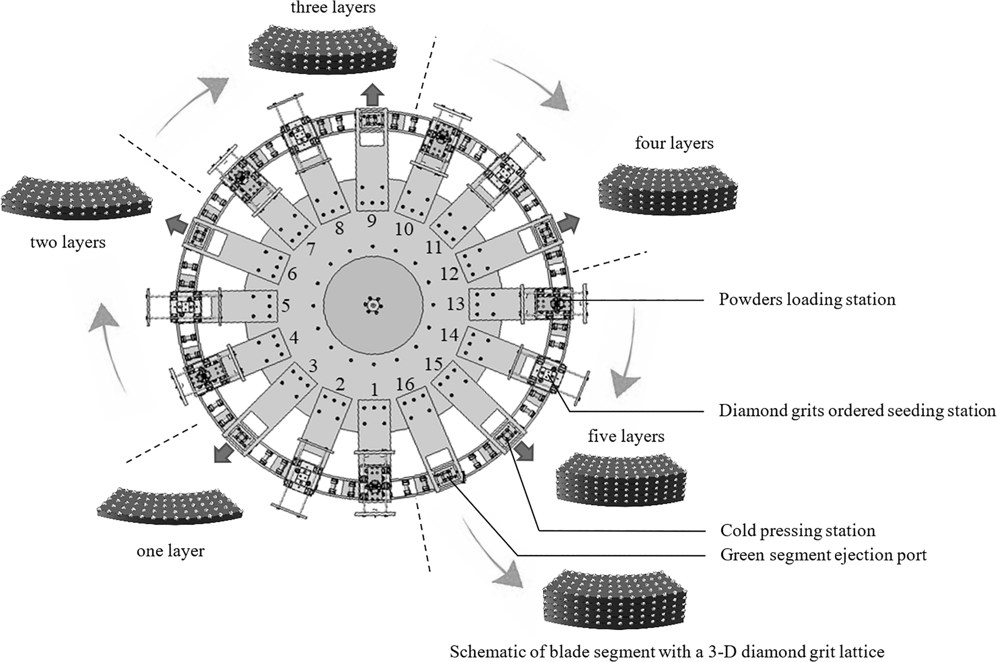
The principle for fabricating 3D green segment with orderly arranged diamond grits.
In practical production, the equipment runs at 5 rpm, which means that 5 pcs of green segment can be produced per minute. Therefore, five cameras were installed at Stations 2, 5, 8, 11, and 14. AME101 with the AOI system using a deep learning algorithm was tested under continuous running conditions at Advanced Technology & Materials Co. Ltd. (Beijing), which is one of the leading global diamond tool manufacturing enterprises in China.
Model performance comparison
Using the unmodified YOLOv5s as a reference, the experimental results of several different models are compared with the benchmark network model. The dataset consists of 1500 scanned pictures, of which 250 pictures are used as the training set and 1250 pictures are used as the test set (Table 2).
YOLOv5s with Different Modules
CA, coordinate attention; DSC, depthwise separable convolution; FLOPs, floating point operations per second.
The results in Table 2 demonstrate that adding the detection head and attention can improve the mAP of the model. By replacing ordinary convolution with depthwise separable convolution and adding detection head and attention, the improved YOLOv5s has a 0.64% increasing accuracy and a 19.6% reduction in both parameters and floating point operations per second (FLOPs) (Fig. 21).
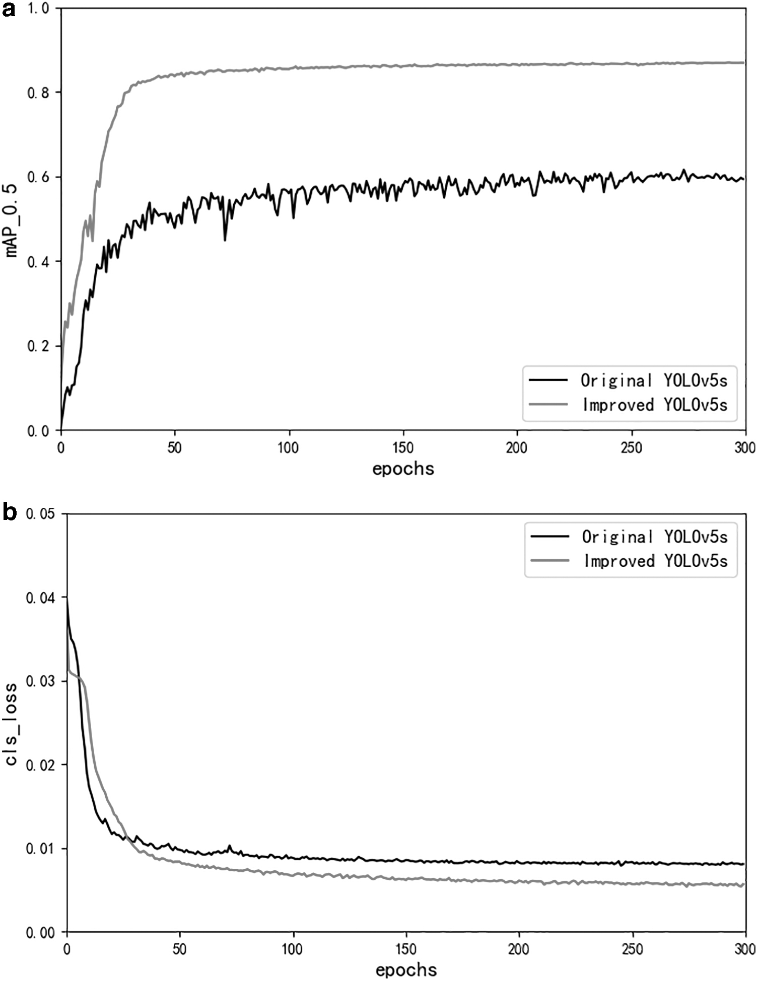
The curve of average accuracy and classification loss.
With the same number of iterations, the improved model is evaluated using mAP_0.5 and cls_loss. In Figure 21a, the mAP of the improved YOLOv5s model is close to 90%, which exceeds the performance of the original model on the training set. In Figure 21b, the cls_loss of both the improve and original models drops below 0.01 after about 300 iterations, the classification loss of the improved model is closer to 0.05. Curve evaluation shows that the improved YOLOv5s has better performance (Fig. 22).
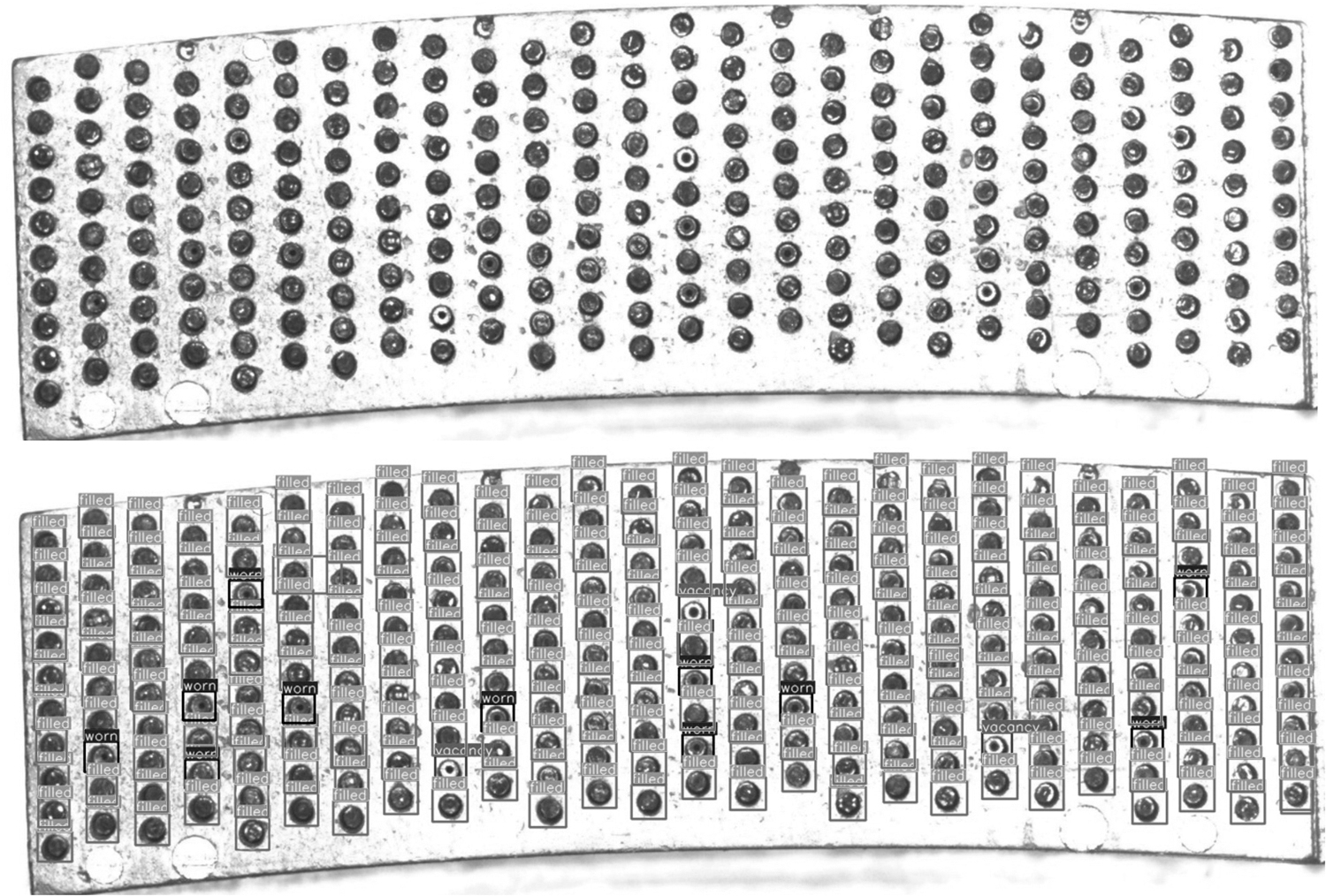
Detection of unfilled pinholes.
The model with the best performance was selected for further evaluation, and the detection results are shown in Figure 22. The predicted boxes can accurately recognize the empty pinholes, and there are basically no cases where the background is recognized as the foreground. Table 3 summarizes the detection time and accuracy of different models.
The Detection Results with Different Models
Testing on the spot
Positioning accuracy test
In the positioning process, microdeviations may exist at the edge of the location point, which causes positioning errors. Generally, the maximum deviation of one side should be less than 2 pixels. In other words, the camera positioning accuracy in the system should be less than 0.1 mm because the pixel accuracy of this system is 0.0217 mm.
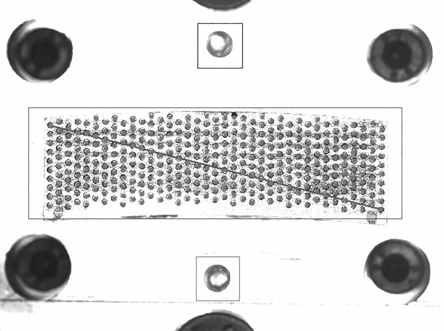
As shown in Figure 23, the positioning accuracy testing method is realized by utilizing the positioning point and the corner point coordinates (the first point and the last point in the needle jig). This is because the distance between the center coordinates of the location points and the corner points is measured and recorded by the original file, which can be used as the benchmark. Then, the distance between the corner points and location points (labeled as ① and ②) is calculated. Compared with the original file, the difference in the data can be used as the result of the positioning accuracy test. As shown in Table 4, the maximum positioning error is 2 pixels, meeting the positioning accuracy requirements of the machine vision inspection system.
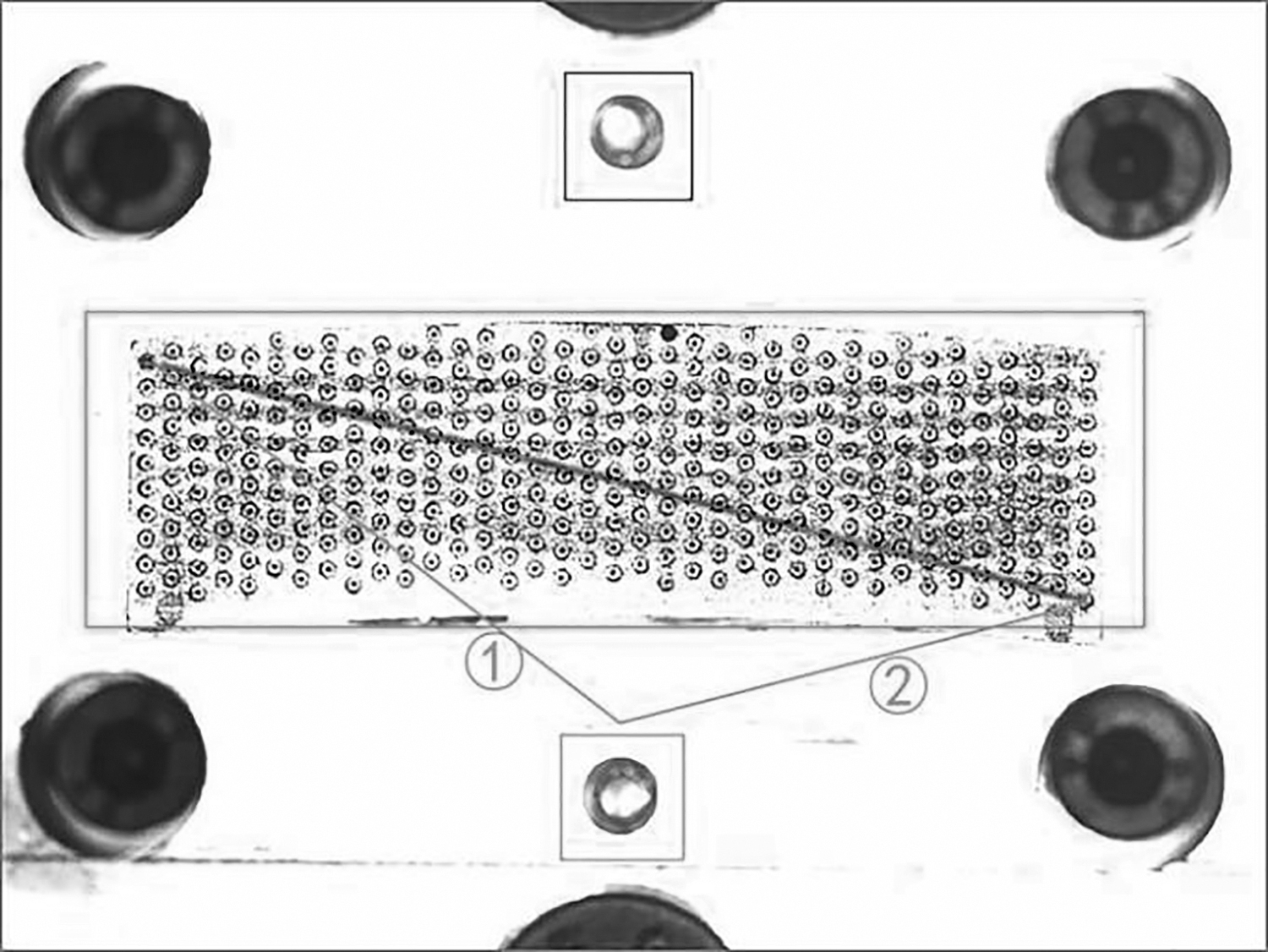
Positioning accuracy test schematic. ① and ② represent distance between the corner points and location points.
Positioning Accuracy Test Results
① and ② represent distance between the corner points and location points.
Inspection accuracy test
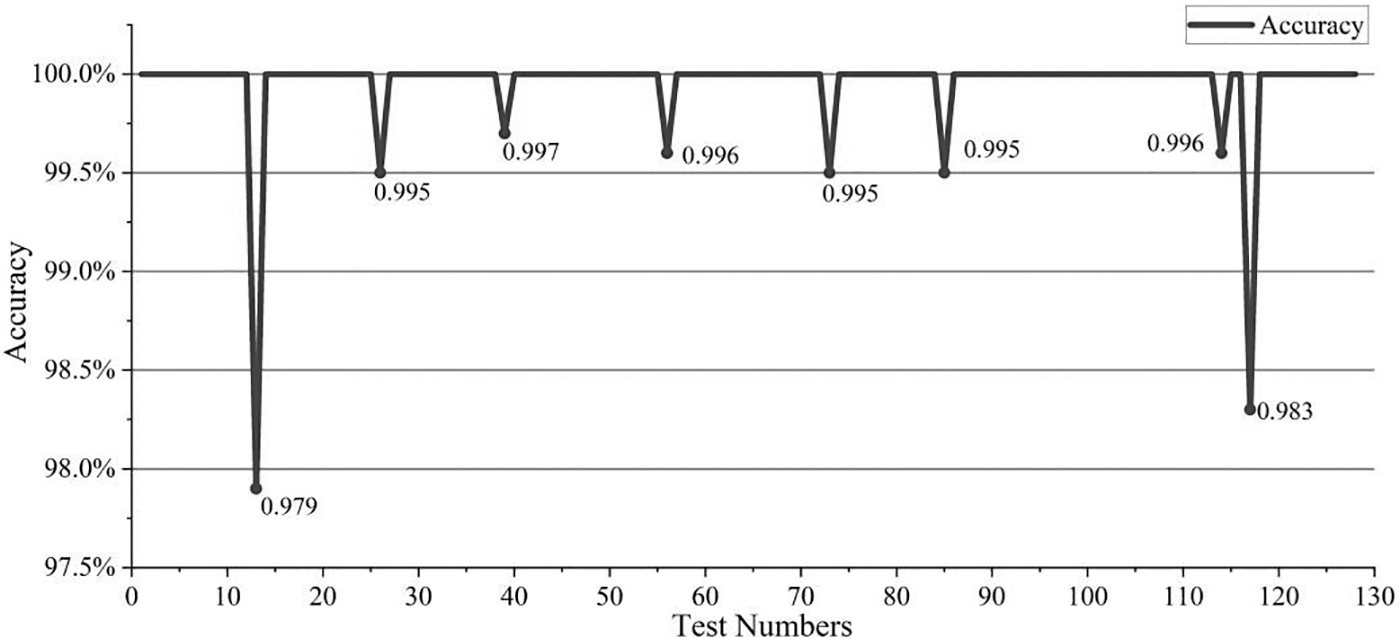
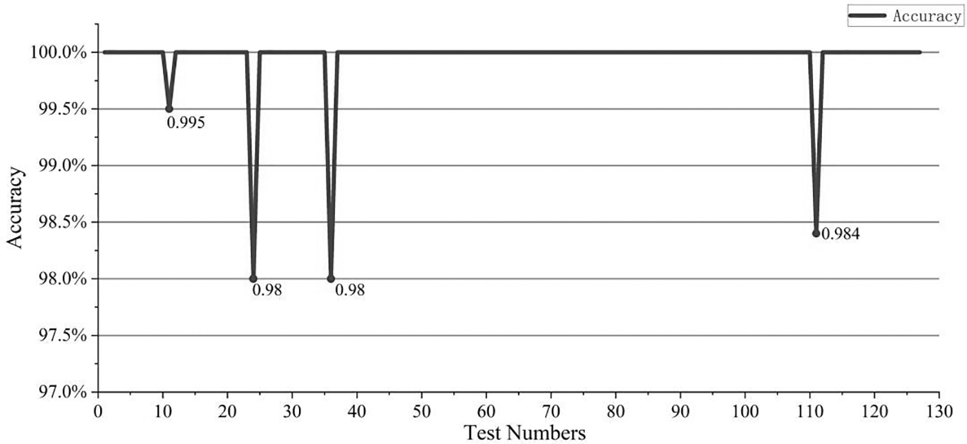
To guarantee the filling rate of diamond grits, the inspection accuracy of every camera must be kept at a high level. In this experiment, 670 data points were collected from AM101, which has been running continuously for 1 year, to verify the accuracy of the machine vision detection system, including 635 valid data points, 128 at Station 2, 127 at Station 5, 127 at Station 8, 128 at Station 11, and 129 at Station 14.
Among them, Station 2 exhibits the lowest detection accuracy, and Station 5 records the highest level of accuracy. The inspection accuracy testing data of Station 2 and Station 5 are shown demonstratively in Figures 24 and 25. The poorest inspection accuracy with 97.9% is generated only once at Station 2, whereas all other data points consistently exceeded the 98% threshold. Collectively, the detection accuracy was higher than 98%.
Inspection testing accuracy of Station 2 in AME101.
Inspection testing accuracy of Station 5 in AME101.
Inspection speed test
To exclude the influence of abnormal operation or needle jig wear on the test results in this test, partial data with 100% inspection accuracy were screened for inspection time analysis, as shown in Table 5. The test results showed that by increasing the number of pinholes, the inspection time increases and remains within a certain range. However, there are some particular data, such as test 6 and test 14. The main reason is that, based on the image recognition module, the inspection time is related to image quality. If the pinhole feature is obvious, it takes less time. Otherwise, it must continue to pass through the image recognition module until it is distinguished. Therefore, the special data are caused by time accumulation. In AME101, the theoretical time required for inspecting the adsorption state of diamond grits is designed to be less than 0.26 s.
Partial Testing Results for the Inspection Time
According to the test results in Table 2, the maximum inspection time is less than 0.11 s. It can be concluded that this online machine vision inspection system matches the working rhythm of AME101 well.
Advantage of the AME101 with AOI system on improved YOLOv5s
Through the application of the online AOI system, both AME100 and AME101 can produce at least 216,000 diamond segments with 5 layers of ordered grit layers every month, which is far beyond the 50,000 pcs per month by ARIX of Shinhan. The diamond grit vacancy rate of the additive manufacturing green segment produced by AME100 was ∼5% at the initial stage. However, due to the influence of pinhole wear, it increased to more than 10% after 3 months of operation. The producer had to replace the needle jig in time. This problem was solved through the application of deep learning algorithm in AME101. Through training with the collected real pictures, the diamond grit vacancy rate in segments produced by AME101 with a machine vision inspection system based on deep learning remained below 5% for more than 1 year under continuous operation.
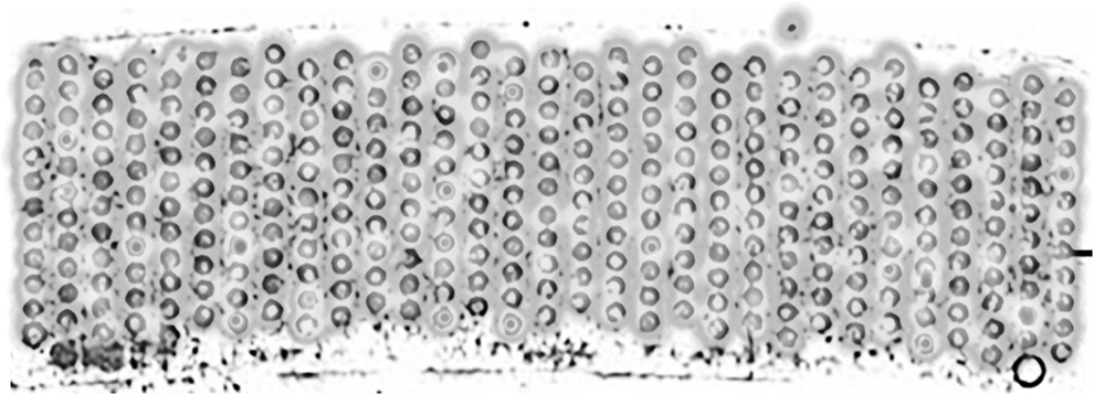
As shown in Figure 26, the diamond grits are orderly arranged in the matrix of the additive manufacturing green segment produced by AME101 with the deep learning algorithm.
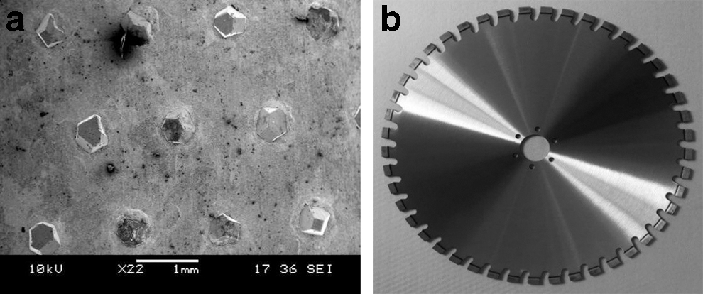
Morphology of the additive manufacturing products by AME101 with the deep learning algorithm.
Conclusions
In this research, the AOI system based on deep learning was applied in the additive manufacturing process to guarantee the quality of diamond green segments with orderly arranged diamond grits. An improved YOLOv5s was developed for the machine vision inspection system to detect the adsorption status of diamond grits. AME101 with the improved YOLOv5s, which has been in continuous operation for 1 year, can still maintain a high filling rate of diamond grits in the metal powder matrix. It provides a powerful safeguard for the mass additive manufacturing of diamond segments with orderly arranged grits.
The improved YOLOv5s, which learns features from a large quantity of data, can quickly distinguish vacant pinholes and even worn pinholes. By replacing ordinary convolution with depthwise separable convolution and adding detection head and attention, compared with the original YOLOv5s, the improved YOLOv5s has an average reduction of 19.6% in both parameters and FLOPs, while increasing the accuracy by 0.64%.
The scanning time for a layer of diamond grits with the inspection system based on the improved model decreased from 6.35 to 5.06 ms.
The additive manufacturing equipment AME101 with a deep learning algorithm, which has been in continuous operation for 1 year, can retain excellent accuracy and robustness. Its inspection accuracy is higher than 98%, and the vacancy rate of diamond grits in the green segment produced by this equipment is less than 5%.
Footnotes
Acknowledgments
The authors sincerely thank Engineer Xiaoyin Wang & Engineer Yongjun Huang for assisting in the manufacture and onsite test of the AME001 and AME101.
Ethical Approval
This article does not contain any studies with human participants or animals performed by any of the authors.
Data Availability and Access
All data supporting the conclusions of this article are included within the article.
Authors' Contributions
Z.F., investigation, writing—original draft, and software. C.D., software and visualization. X.X., data curation and investigation. Y.L., data curation and formal analysis. S.W., conceptualization, funding acquisition, investigation, and writing—review and editing.
Author Disclosure Statement
No competing financial interests exist.