
Abstract
Selective laser melting (SLM) is a multidisciplinary manufacturing technology in which information technology, new material technology, and manufacturing technology are integrated. It is considered one of the most promising additive manufacturing technologies due to its capability for flexible customization and its advantages in forming complex components, and it has found wide application in the fields of aerospace, rapid prototyping, and medical equipment, among others. However, there are certain challenges that need to be addressed for the further development and application of SLM technology. These challenges include insufficient manufacturing process stability, difficulty in real-time monitoring of manufacturing quality, and the immaturity of the technology regarding the real-time adjustment of process parameters. The occurrence of defects during the SLM process is a major factor contributing to these challenges. To ensure adequate quality control, it is essential that defects are continuously monitored in real time, with the provision of timely feedback to the SLM manufacturing system. Thus, a significant point of focus in this field of research is to explore the adjustment of process parameters based on defect monitoring information toward effectively controlling the occurrence of defects. In this literature review, we review the common defect types and their generation mechanisms in the SLM process, also providing a detailed description of the signals generated by the SLM process, such as acoustic, optical, and thermal signals, as well as methods for their monitoring. The signal data processing methods based on machine learning techniques have been summarized. In conclusion, this review provides a summary of the research conducted in this field and suggestions for future research directions for machine learning in the field of SLM intelligent monitoring.
Introduction
Additive manufacturing, commonly referred to as rapid prototyping or 3D printing, has the ability to deposit, combine, or solidify substances in order to create products based on computer-aided design models. 1 It is an advanced manufacturing technique that has emerged in recent years in which materials are stacked, layer by layer, to form physical parts. Its status as a pioneering manufacturing technique is now indisputable, owing to its exceptional efficiency in manufacturing, potential for scalability, affordability, and ability to handle complexity.2,3 At present, selective laser melting (SLM) is considered to be one of the most promising and advanced additive manufacturing technologies, and it is widely used in medical treatment, shipbuilding, and aerospace, among other fields.4–7 In SLM, the 3D model is first discretely designed layer by layer, and the laser beam is then controlled to scan the powder bed according to a specific trajectory such that the powder material is melted and stacked layer by layer during forming. 8 The design limitations of traditional methods are successfully surpassed by this technology, which demonstrates its capability of fabricating compact and intricate structures through metallurgical bonding. Furthermore, this technology offers exceptional mechanical properties resulting from manufacture.9–11 As SLM forming is a very complicated metallurgical process, spatters, porosity, balling, and other defects also result.12–17 These defects limit further application of the SLM process, so how to monitor the occurrence of these defects in a timely manner, and even predict possible defects in advance, is of interest in terms of improving the quality of formed parts and enhancing melting of the laser powder bed. The stability and repeatability of the process are the focus of various research teams.
In traditional manufacturing processes, routine quality testing, also known as offline monitoring, is typically conducted after the product is made. Common methods used for offline monitoring include those based on ultrasound, X-ray, and others. Emerging detection techniques, such as CT testing and laser ultrasonic testing, are also being utilized.18–20 However, the SLM manufacturing process differs from traditional processes, as most defects occur during the SLM forming process and are influenced by various factors. Therefore, real-time monitoring of the manufacturing process and online defect detection are necessary to enhance the quality of SLM parts. Online defect monitoring technology enables comprehensive real-time recording of the entire SLM manufacturing process and offers several advantages. First, it allows immediate discovery of defect location, type, and other information, facilitating prompt assessment of whether production should be halted to minimize subsequent loss. Second, defects can be repaired online by modifying the process strategy and parameters, thereby improving the part quality. Last, online monitoring enables the study of SLM process mechanisms and optimization of process parameters by providing a theoretical foundation for practical production applications. Since online monitoring technology can be used to detect and repair defects in real time, it significantly reduces part scrap rate, making it highly valuable for enhancing the quality of SLM parts. Currently, machine learning technology is extensively used across various industries, and its application in defect identification is gaining attention in the SLM manufacturing process. By incorporating machine learning algorithms, the accuracy and efficiency of defect identification can be enhanced.
This article begins by discussing the common types of defects and the mechanisms underlying their formation in the SLM process. Then, an overview of the developments and research status of defect monitoring technology in the SLM process is provided, focusing on different signal acquisition methods such as those involving optical signals and temperature signals. The article also highlights the use of machine learning methods for identifying and processing monitoring signals. The shortcomings of existing monitoring technology are summarized, and prospects for the future development of this technology are discussed.
Types of Defects and Their Mechanisms
The common defects resulting from the SLM process include spatters, porosity, balling, cracks, lack of fusion, poor surface quality, geometric deformation, and more. These defects represent the biggest bottleneck obstructing the wide application of SLM technology in industry. 21 In order to break through this bottleneck, it is necessary to understand the physical processes of SLM in depth, in addition to the defect types and their mechanisms during the SLM process.
Principle and physical process of SLM
The process for SLM can be succinctly described as follows: Initially, a 3D model is created and prepared for deriving the sliced model. Subsequently, the process parameters and laser scanning path are determined based on the structural and material properties. Ultimately, a laser beam with high-energy density is employed to melt the metal powder along a predetermined path. This results in the gradual accumulation of metal powder layers, ultimately forming the desired component (Fig. 1). The key stages of the SLM process consist of powder spreading and laser melting. During the powder spreading stage, a roller is employed to evenly distribute the powder onto the bed before printing each layer, whereas any unmelted powder is collected and stored in the residue cylinder. In the laser melting stage, a high-energy laser rapidly melts the metal powder, depositing it layer by layer to fabricate the intended component. By iteratively executing these two stages, the final fabricated part is obtained.
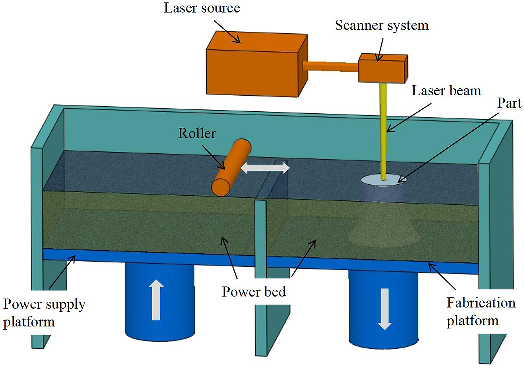
Schematic of the selective laser melting process.
In the SLM process, multiple physical and chemical phenomena occur over different geometries and time scales, resulting in various related physical effects. 22 For example, the expansion of gas influences the dynamics of powder particles, and the interaction between the laser and thermal fluids involves the transition from solid to liquid. Additionally, solid-state transformations, such as precipitation during remelting and inherent heat treatment, need to be taken into account. Finally, it is crucial to consider the phase transition in order to understand the mechanism of defect formation. When the laser interacts with the metal powder, it triggers the material transition between all four states of matter: solid, liquid, vapor, and plasma (Fig. 2). 23 However, there is currently a lack of physics-based models that can fully capture the complexity of these transitions. Furthermore, the rapid and repeated thermal cycles in the SLM process create significant thermal gradients, which can result in the formation of unstable structural and mechanical states. These states can lead to metallurgical defects that have the potential to compromise the properties of the final part.24,25
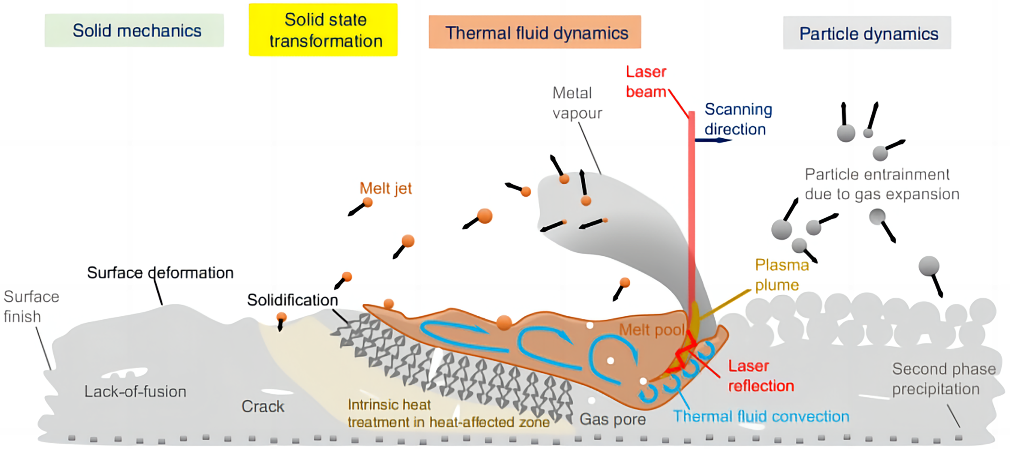
A schematic illustration of multiscale, multiphysics phenomena in the SLM process. 23 SLM, selective laser melting.
Types of defects and their mechanisms
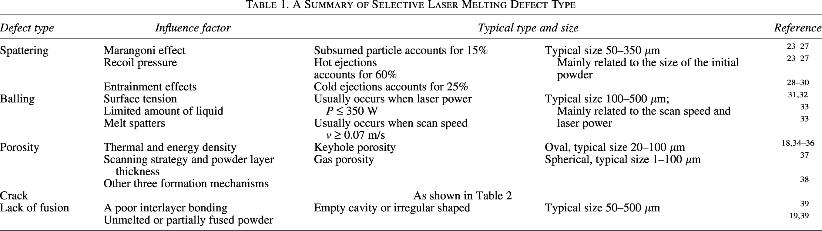
The defects in the SLM process can be categorized into two types: defects in the powdering process and defects in the forming process. Defects in the powdering process may manifest as irregular powder layers, while defects in the forming process can include spatter, balling, porosity, crack, lack of fusion, poor surface quality, geometric deformation, and more. In the following, different common defects and their formation processes are introduced, and the influence of key influence factors on these different defects is summarized (Table 1).
A Summary of Selective Laser Melting Defect Type
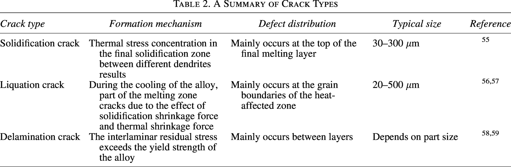
A Summary of Crack Types
Spatter and its mechanism
Spatter is a common defect in the SLM process and is an unavoidable occurrence during laser processing. When the laser interacts with the powder, molten material is expelled from the molten pool, solidifies, and accumulates in nearby areas, forming noticeable large and dark solidified molten particles on the powder bed. These particles have a direct impact on the quality of the final parts. Consequently, spatter is a significant contributing factor to other defects. Wang et al. 26 studied the influence of laser energy on spattering, and the mechanism and characteristics of spatter generation in the SLM process and their effect on material properties were investigated. It was found that the intensity and number of spatters increased with increasing laser energy input, and there were even cases of metal liquid jets up to 11 cm. The main sources of spattering include recoil pressure, the Marangoni effect, and thermal effects in the molten pool. Figure 3 shows the mechanisms for different types of spatters.
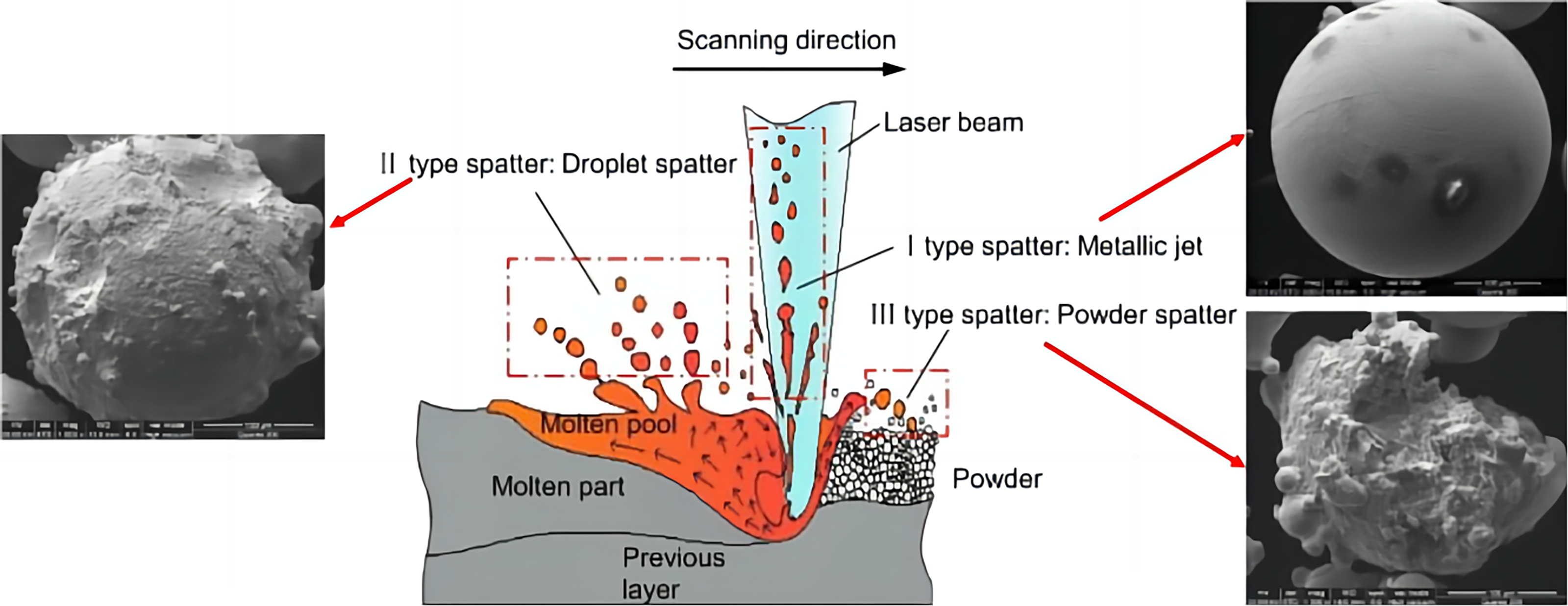
Formation mechanisms of different types of spatter: type I spherical spattering, type II coarse spherical, and type III irregular spattering. 26
Spattering driven by recoil pressure: One of the spatter mechanisms observed in SLM can be elucidated through the occurrence of a phenomenon referred to as recoil pressure. 27 Recoil pressure denotes a vigorous evaporation of metal, induced by the laser beam. When the laser beam rapidly heats the powder bed, a vapor vortex emerges, intensifying the recoil pressure and leading to ejection of the molten material from the melt pool.28,40 The laser beam coming into contact with the powder bed leads to an increase in surface temperature, which subsequently causes the formation of the melt pool. Gradually, the temperature escalates further, reaching the vaporization point, thereby resulting in the generation of a metallic vapor jet directed toward the laser beam, and the motion of the melt pool expels molten metal spatters from the pool.41,42
Spattering driven by the Marangoni effect: The Marangoni effect is the phenomenon of mass shifting due to the gradient of tension between two liquid interfaces with different surface tensions. Specifically, a liquid with high surface tension exerts a strong pull on a liquid with low surface tension around it, creating a surface tension gradient that causes the liquid to flow from a direction of low surface tension to high tension. As the energy density of the laser beam increases, Marangoni convection becomes more obvious, leading to melt pool instability and the appearance of pores.29,43 Furthermore, high scanning speeds can also lead to instability in the melt pool, thereby increasing surface tension and Marangoni convection. Even a small temperature field and low temperature in the melt pool contribute to the instability of the melt pool flow and cause Marangoni convection; all of these Marangoni effects cause spatters.30,44 In addition, the instability of the molten pool leads to an increase in surface tension and, consequently, more Marangoni convection, which in turn leads to increased spattering.45,46
Spattering driven by entrainment effects: Based on the study conducted by Ly et al., 43 the metallic vapor vortex created by the laser beam and shield gas raises cold powder particles and metal droplets from the powder bed. In the SLM process, approximately 60% of the observed occurrences entail the expulsion of heated material, while 25% involve the expulsion of cooled material.46,47 In accordance with the findings by Wang et al., 26 three distinct categories of entrainment-driven spatters have been identified: (i) particles that are encompassed by the melt pool, originating from the powder bed being in close proximity to the melt pool; (ii) cold powder particles that are drawn toward the jet by the vapor vortex; and (iii) powder particles that collide with the laser beam and consequently transform into droplet spatters.31,32
The solidification of spatter on the surface of the powder layer can have negative effects on subsequent powder spreading, leading to uneven and irregular powder distribution; it potentially harms SLM-formed parts and causes various defects. 48 Therefore, it is crucial to reduce spatter defects in the SLM process in order to improve the quality of SLM parts. One approach to mitigate the impact of spatter on the metal powder bed is to eliminate it using high-speed protective airflow. 49 However, excessive airflow may damage the surface integrity of the powder layer. Thus, finding ways to reduce spatter defects during the SLM process will be a key focus of future research.
Balling and its mechanism
Balling is a common defect in the SLM process that occurs due to the combined effects of surface tension, gravity, and the surrounding medium following laser irradiation.50,51 This defect is characterized by the solidification of liquid metal into spherical droplets, which is caused by surface tension. The energy density of the laser beam plays a crucial role in the occurrence of balling. If the energy density is too low, the metal powder may not melt completely, resulting in the formation of balling. On the contrary, if the energy density is too high, the liquid metal may spatter onto the unmelted metal powder, also leading to balling. It is important to note that the balling effect not only impacts the quality of the final product but also contributes to the formation of other defects in the SLM process. Understanding and controlling the balling effect is therefore essential for improving the overall efficiency and quality of the SLM process.33,52 Figure 4 shows a typical example of the balling phenomenon.53,54 Gu et al.34,35 conducted a comprehensive analysis on the factors influencing the formation of both large and small balling effects. They extensively categorized these factors into two distinct types: coarsened balls caused by limited liquid and micrometer-scale balls induced by melt spatters.
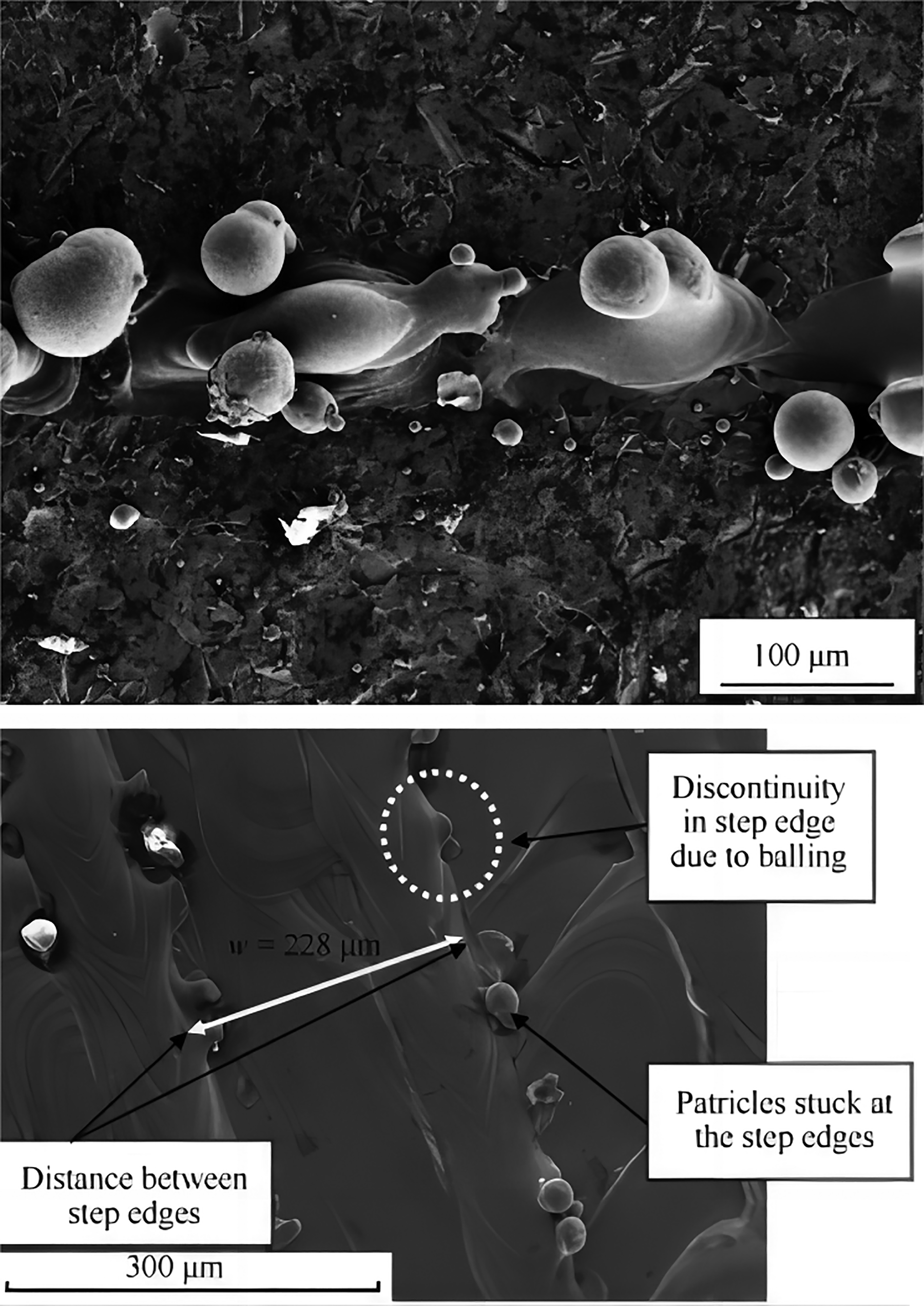
Balling phenomenon during the SLM process. 48
Coarsened balls caused by limited liquid formation: The amount of liquid formation depends on the operating temperature of the sintering system, which is controlled by two main parameters (laser power and scan speed) during a single line scanning. When there is a limited amount of liquid, efficient bonding between the neighboring balls cannot be achieved due to the insufficient growth of sintering necks between metal agglomerates. On the contrary, employing a lower laser intensity results in a restricted degree of undercooling in the molten material, which subsequently leads to the formation of enlarged and fragmented dendritic structures on the outer layer of the solidified spheres.
Micrometer-scale balls caused by melt spatters: Based on the findings of Gu et al., 35 the impact of scanning velocity on the instability of the liquid track in capillary action has been observed. Increasing the scanning speed and reducing the energy density of the laser input result in a decrease in both the working temperature and the diameter of the molten cylindrical path. This decrease further contributes to the instability of the molten substance. As a result, the reduced surface energy of the liquid at shorter length scales causes numerous small droplets of liquid to spatter from the surface of the molten track. Once the material solidifies, a substantial quantity of micrometer-sized spherical spatters forms around the molten surface; this process gives rise to the phenomenon known as balling.
Porosity and its mechanism
Porosity is a critical defect in SLM parts and is known to significantly affect their mechanical properties. Therefore, the monitoring and control of porosity is also one of the key research directions in research on the SLM process. During the SLM process, the rapid melting and solidification of materials, along with the turbulent behavior of the molten pool, contribute to the formation of pores. The size, number, morphology, and location of these pores play a crucial role in determining the mechanical properties of the final parts. Higher porosity levels can lead to a shorter fatigue life of the final parts, and the location of pores near the surface, compared to other areas, has a greater impact on the fatigue performance.36,37
Bauerei et al. 38 developed a mesoscopic numerical model using the Lattice Boltzmann method (its principle is to describe the microscopic behavior of a fluid by tracing a distribution function over discrete lattice points) to simulate the formation and growth of nonfusion pores, in which the thermocapillary effect and wetting effect are considered. Gong et al. 33 investigated the relationship between different pore types and energy density in the SLM processing of TC4 metal powder. They established process windows based on the pore types, which included high-density area, overmelting area, insufficient fusion area, and super-heating area. King et al. 55 examined the conditions for transitioning from small pore mode to thermal conduction mode in the SLM processing of 316L stainless steel.
Using experiments and numerical simulations, Qiu et al. 46 conducted a study on the correlation between scanning speed, powder layer thickness, and gas porosity in SLM structures made of TC4 alloy. Their findings revealed a direct relationship between higher scanning speed and powder layer thickness with increased gas porosity. Additionally, they observed that thick powder layers intensified the fluctuation and oscillation behavior of the molten pool, resulting in increased porosity.
Hojjatzadeh et al. 15 utilized high-speed (2 MHz) and high-resolution (about 2 μm) X-rays to observe the development of porosity in the SLM process of four different metal powders. They identified and analyzed six mechanisms that contribute to the formation of pores. Three of these mechanisms have been previously reported: pores caused by small pores, pores originating from raw materials, and pores resulting from the evaporation of unstable materials at melting boundaries or the expansion of small amounts of trapped gas. The researchers also discovered three new mechanisms: pores trapped by surface fluctuations in the molten pool, pores formed by oscillations in shallower depression regions due to recoil pressure (distinct from those formed by the collapse of small pores), and pores formed by cracks. Additionally, they observed that the high-temperature gradient in the SLM process generates a thermal capillary force that rapidly eliminates some of the pores within the melting pool. This finding offers insights into mitigating pore formation in the SLM process. 24
Crack and its mechanism
The stacked manufacturing method of SLM technology frequently results in intricate residual stress, which can result in crack defects in printed parts and diminish the fatigue strength and other mechanical properties. These crack defects are categorized as solidification cracks, liquation cracks, and delamination based on their formation mechanisms. The formation of cracks mainly depends on the material used, and postprocessing methods are not always successful in eliminating these defects. As a result, managing and preventing crack formation poses a significant challenge in additive manufacturing. The main crack types and their formation mechanism and distribution are shown in Table 2.
Solidification crack is caused by the solidification temperature near the cooling process because the liquid phase in the crystallization region cannot support the shrinkage stress caused by the solidification. Metals experience both solidification shrinkage and thermal shrinkage, leading to a tendency for the solidified layer to shrink. However, the temperature of the substrate or the previously deposited layer is lower than that of the deposited layer, causing the deposited layer to shrink more than the layer beneath it. As a result, the shrinkage of the solidified layer is impeded by the substrate or the previously deposited layer, creating tensile stress within the solidified layer. If this tensile stress surpasses the strength of the solidified metal, cracks will form along the grain boundaries.
Figure 5 illustrates the generation and propagation model of solidification cracks, which is primarily divided into three stages. 56 First stage, nucleation of intergranular hot cracks: Cracks nucleate intergranularly in subsurface where maximum volumetric strain is localized and volume fraction of liquid is <0.1. The crack nuclei occur at solute-enriched liquid pockets that remain trapped in the increasingly impermeable semisolid skeleton. Second stage, coalescence of cracks via intergranular fracture: as the applied strain increases, cracks coalesce through intergranular fracture, the coalescence path is preferential to the direction of the heat source and propagates through the grain boundaries to solidifying dendrites. Third stage, propagation through interdendritic hot tearing: Interdendritic hot tearing occurs along the boundaries between solidifying columnar dendrites with higher liquid fraction.
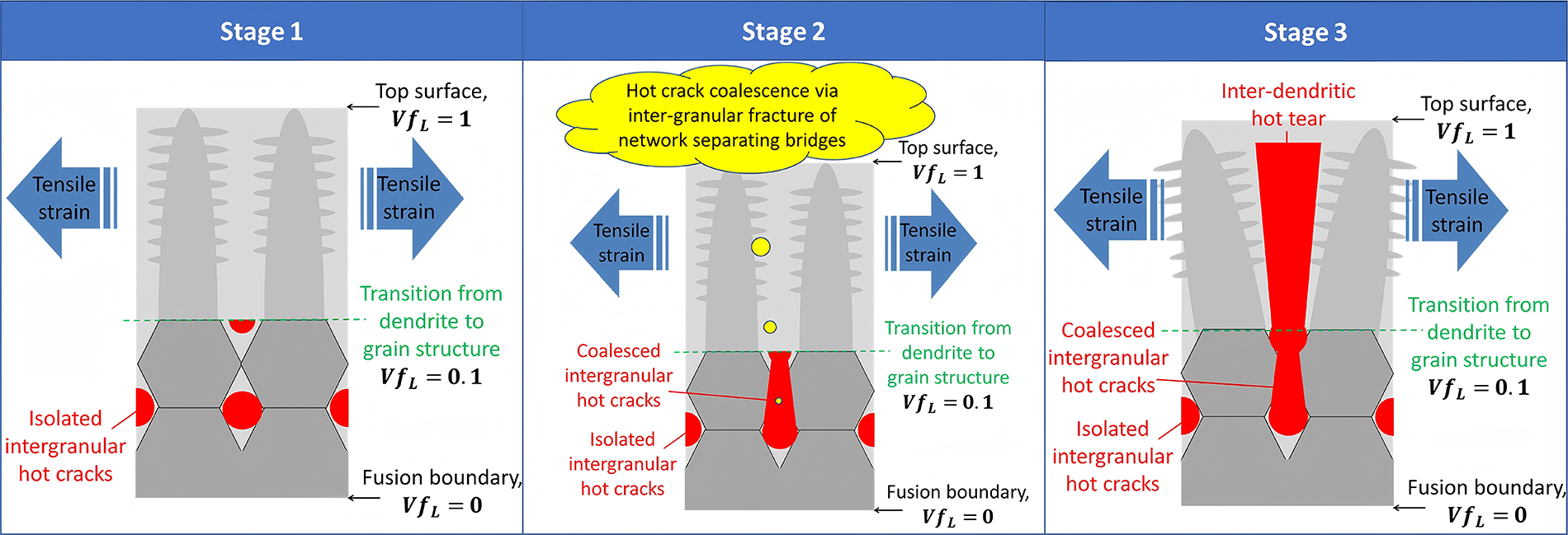
The generation and propagation model of solidification cracks. 58
Liquation cracks are commonly observed in the mushy zone or partially melted zone. 57 In the partial melting zone, the alloy is rapidly heated below the liquidus line, leading to the melting of certain grain boundary precipitated phases, such as low melting point carbides. Alloys with a wide mushy zone (where the liquidus and solidus lines are significantly apart, like nickel-based superalloys), high solidification speed (resulting in a large molten pool, as seen in Ti-6Al-4V), and high thermal expansion coefficient are particularly prone to liquefaction cracking. 60
The initial stage of the process involves liquefaction at the grain boundaries (Fig. 6a). 58 During thermal cycles, low melting point eutectic or impurity phases precipitate at these boundaries, leading to the formation of liquid metal that fills the gaps. This phase experiences minimal heat input and thermal stress, allowing the crystal to adapt to stress changes through plastic deformation. Consequently, the grain boundaries are once again covered by solidifying metal. Despite liquefaction at the grain boundary, the shrinkage stress is minimal, preventing the occurrence of cracks. The second stage marks the beginning of liquefaction cracking, where increasing heat input leads to more liquefied grain boundaries. As the cooling process progresses, the thermal stress rises, significantly reducing the bonding force between adjacent grain boundaries. When this stress surpasses the limit of plastic deformation of grains, discrete microcracks form at the grain boundaries (Fig. 6b). In the third stage, the cracks are not only a result of thermal stress but also of compositional segregation. During the third stage of crack expansion, when the thermal stress surpasses the grain boundary bonding force, microcracks will expand freely along the grain boundaries. As these cracks continue to grow and accumulate, visible cracks form (Fig. 6c).
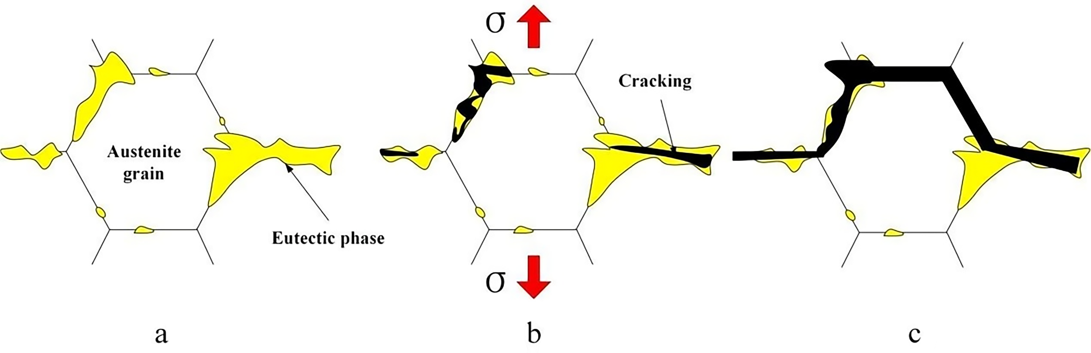
Liquation cracking model. 39
Delamination crack is a distinct form of crack resulting from the separation of adjacent layers within a component due to incomplete melting between layers. This phenomenon is primarily triggered by either inadequate powder melting or incomplete remelting of the underlying solid material. 56 Unlike solidification and liquefaction cracks, which are microscopic in nature, delamination is a macroscopic crack that cannot be eliminated through postprocessing.
Delamination crack is primarily attributed to the temperature gradient mechanism, which is driven by the sharp thermal gradient within the solid material beneath the heat source.59,61 The high temperature of the upper layer of the solid substrate leads to expansion, while the lower temperature of the lower layer restricts this expansion, resulting in compressive stress in the upper layer of the substrate. This compressive stress may exceed the material’s yield strength, leading to plastic deformation in the upper layer. As these plastically deformed layers cool down, they transition from a compressive state to a tensile state due to residual tensile stress, potentially leading to cracking.
Lack of fusion and its mechanisms
Lack of fusion (LOF) is a common large-scale volumetric defect in the SLM process. It is difficult to completely eliminate LOF by subsequent heat treatment such as hot isostatic pressing (HIP, a postprocessing method in which the product is densified by placing it in a closed container and applying high temperature and high pressure), which will seriously affect the properties of the material such as tensile strength, fatigue strength, and creep strength. The size of LOF areas varies greatly among different materials and parts, ranging from a few microns to over 200 μm, exhibiting diverse shapes. These shapes can include complete crack shapes and other forms that are not fused, influenced by manufacturing process parameters. It has been observed that high scanning speed, large scanning distance, and increased powder layer thickness all contribute to the occurrence of LOF, which results in the increase in porosity. 39 There are two typical types of LOF in the SLM process: one is LOF caused by insufficient melting during the solidification process, and the other is LOF caused by unmelted metal powder. 62
Signal Monitoring of the SLM Process
In the SLM forming process, the interaction between laser and material will produce a lot of signal information, including sound, light, heat, electricity, and radiation, which can provide feedback regarding the forming quality. The defect monitoring technology of the SLM forming process is based on the monitoring of these signals. For each different type of signal information, the monitoring methods and principles differ, each with its own advantages but also limitations. Several common information types and their monitoring methods are described in the following (Table 3).
A Summary of Signal Monitoring of the Selective Laser Melting Process
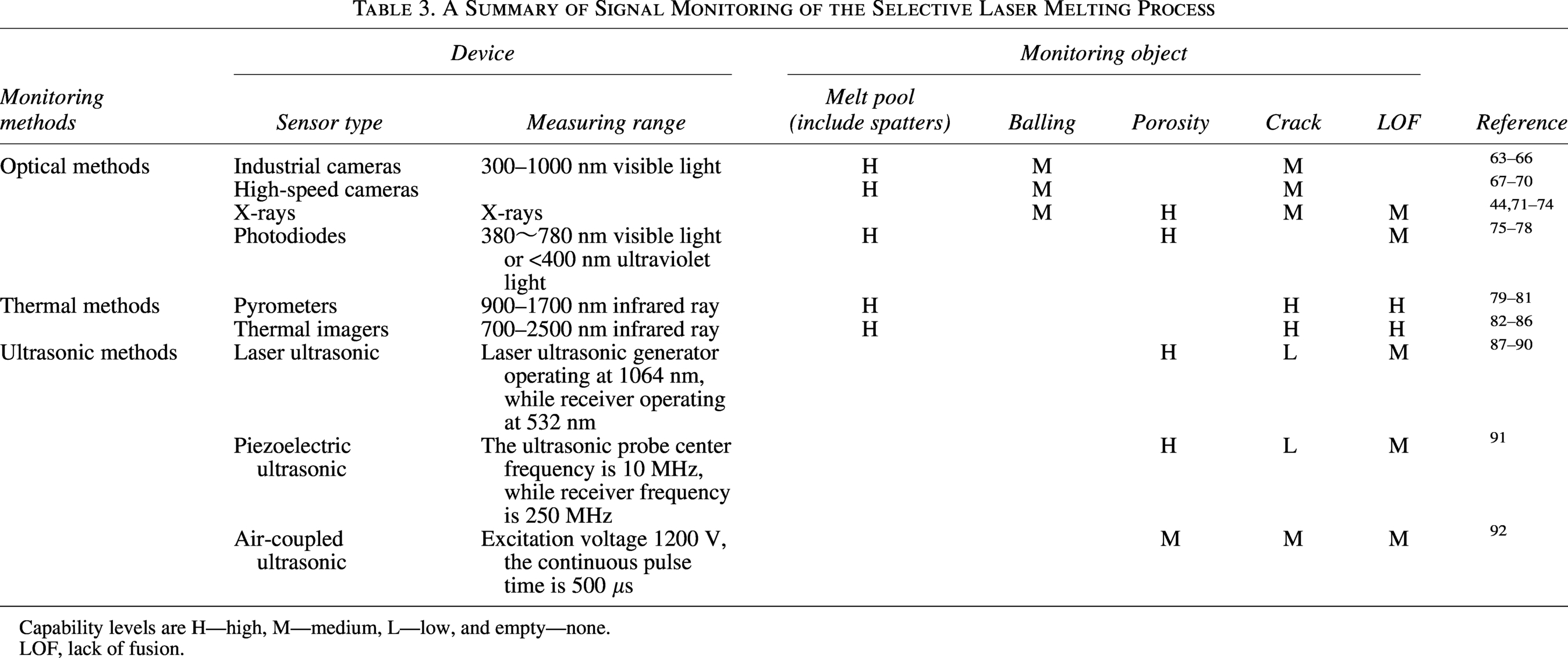
Capability levels are H—high, M—medium, L—low, and empty—none.
LOF, lack of fusion.
Optical methods
In the SLM process, various optical signals are generated by the powder layer, metal vapor, spatter, molten pool, pore, solidified layer, and others. These optical signals can be effectively monitored using the corresponding optical sensors, and monitoring of the SLM process through optical signals is the most widely employed method. Researchers utilize industrial cameras, high-speed cameras, X-rays, and photodiodes to capture optical signals during the SLM process. They then extract features from these signals to monitor the quality and detect any defects in the SLM parts. The main sensors used for optical signal monitoring in the SLM process are as follows.
Industrial cameras
The primary function of an industrial camera is to convert optical signals into electrical signals in an organized manner. In comparison to traditional civilian cameras, industrial cameras offer advantages such as high image stability, strong transmission capabilities, and effective resistance to interference. Despite having a lower sampling frequency, industrial cameras are commonly utilized for monitoring the surface quality of powder layers and solidified layers due to their affordability and higher resolution.
Gobert et al. 63 employed an industrial camera to acquire the detailed features of each component layer in the SLM process, and they used 3D CT scanning slices as reference markers. By utilizing machine learning technology, they were able to rapidly distinguish between the discontinuous and normal states of the solidified layer. Aminzadeh et al. 64 developed an imaging system with an industrial camera; they used industrial camera images for online quality detection, where pores and clear surface features could be visualized in real time, which solves the difficulties and problems in previous studies. Industrial cameras have been employed in numerous research investigations to evaluate the interaction between laser and powder, thereby fostering crucial insights into spatter,93,94 the signature of the melt pool, 16 the quality of the surface, 65 and any anomalies in the powder bed. 66
High-speed cameras
A high-speed camera is a type of camera used for high-speed photography. It has a higher sampling frequency compared to ordinary industrial cameras. In the SLM process, it is widely used for monitoring defects. This camera allows for visual monitoring of the melt pool and can detect characteristics such as pores and spatter, enabling quick identification of defects.
The two common high-speed camera layout modes in the SLM process are coaxial and paraxial. Alkahari et al. 95 used the high-speed camera to monitor the coaxial SLM process and investigated the characteristics of powder melting. They also studied the two common high-speed camera layout methods in the SLM process, namely coaxial and paraxial. By utilizing the high-speed camera to monitor the coaxial SLM process, they examined the correlation between powder melting characteristics and process parameters and found that the laser power and laser scanning speed impact the melting pool area, solidification width, solidified condensate diameter, and spatter. These process parameters also influence the amount of molten mass resulting in the powder. Matilainen et al. 67 employed the high-speed camera to observe the SLM process and investigate the correlation between the duration of laser activation and the occurrence of pore defects.
Kleszczynski et al. 68 employed high-speed imaging techniques to identify various process flaws in the SLM process. These flaws pertained to both the stability of the process, encompassing factors such as inadequate powder supply, faulty support connection, and superelevation, as well as the quality of the final parts, including issues like surface damage, substandard appearance, and dimensional accuracy. A significant advantage of utilizing high-speed imaging lies in its potential to incorporate computer vision and machine learning methods for the purpose of mitigating defects that occur during the SLM process. Scime et al. 69 proposed an approach to effectively transform images obtained using a high-speed camera, which has a fixed field of view, into a more valuable format by employing coordinate transformation.
The use of high-speed cameras in the SLM process enables direct observation of phenomena like the molten pool and spatter. This observation method proves to be an effective approach for extracting features and identifying defects through image analysis. To capture the typical features of a specific region, different techniques such as filtering, auxiliary light sources, and attenuation can be utilized. However, accurately establishing the relationship between image features and defects remains a significant challenge in this field.
X-rays
X-rays are a type of electromagnetic wave characterized by their extremely high frequency, extremely short wavelength, and high energy. They have a frequency and energy that are second only to gamma rays, making them highly penetrating. This unique property allows X-rays to provide intuitive and detailed information about internal defects, such as the size and location of pores and cracks, in contrast to other monitoring methods. They can effectively reflect the 3D shape and allow the precise location of these defects.
Ggelein et al. 70 utilized optical tomography technology to monitor the entire SLM process in real time. They conducted X-ray imaging on various samples and obtained detection probability curves. Then, they established a correlation between defects and optical tomography, accurately identifying defects such as LOF of SLM parts. To investigate the influence of geometric defects on the mechanical properties of SLM-printed parts, Wang et al. 71 employed X-ray to reconstruct the 3D structure and utilized image-based Finite Element Method (FEM, a widely used numerical analysis method, mainly used to solve complex engineering and mathematical problems). They compared these results with the data obtained from the defect-free FEM model, enabling them to analyze the morphological characteristics of cracks and examine the relationship between the failure mechanism of SLM parts.
X-rays have also been utilized for the characterization of size, shape, and porosity of powder particles. 72 Another significant application of X-rays is dimensional accuracy determination through the metrology of the SLM parts. 73 Even though X-ray can be used to visually track the real-time presence and position of internal defects, the expense associated with X-ray monitoring must be reduced, particularly the cost of high-speed and high-resolution X-ray in situ monitoring, which tends to be more expensive. Consequently, it is commonly employed for scrutinizing alternative monitoring techniques and validation. 74
Photodiodes
Photoelectric sensors, also known as photodiodes, have the ability to convert light signals into electrical signals. They can generate analog electrical signals by measuring the intensity of the received light or enable the transition between different states within digital circuits. 44 During the process of SLM, intense radiation is generated from sources such as molten pools, sputtering, and metal vapors. Information useful for process status and part quality can be obtained from these radiated signals using photodiodes.
In Coeck et al., 96 a melting pool monitoring system was developed. This system consists of photodiodes placed on both sides of the forming platform of the SLM device to monitor the optical signals generated throughout the process, and it was able to predict the size and location of porosity defects with a porosity prediction sensitivity of 90%. Montazeri et al. 75 utilized photodiodes to monitor the SLM forming process and then applied spectral theory to analyze the monitoring data, enabling the detection of cross-contamination between materials during the SLM process. Using both coaxial and noncoaxial configurations, Nadipalli et al. 76 employed photodiodes to monitor the powder bed and molten pool status in an open architecture pulsed laser system.
Zhang et al. 77 introduced an optimized method, called the photodiode zone monitoring method, to monitor the state of the molten pool. Using this method, light signals are collected in different zones during the processing process, enhancing the accuracy of data collection in the SLM process. The characteristics of the alumina single-track molten pool were also explored in the study, examining how they are influenced by laser power. Additionally, an analysis was conducted to ascertain the correlation between molten pool characteristics and various process parameters, examining scanning speed, scanning spacing, and laser power.
Thermal methods
Thermal transmission plays a crucial role in various aspects of the SLM process. It affects the formation and behavior of the molten pool, the cooling and solidification of the liquid metal, and the thermal cycle of the solidified layer. Therefore, it is essential to understand the effects of thermal transmission in order to optimize these processes and improve overall efficiency. By examining how heat is transferred during these stages, researchers can identify areas for improvement and potentially develop new techniques to enhance thermal transmission, resulting in higher-quality products. The complex temperature history during the SLM process directly influences the microstructure, residual stress, and deformation of the parts. Achieving a uniform temperature distribution is crucial for producing high-quality parts, while an irregular temperature distribution can negatively impact the integrity and quality of the component structure. Hence, studying the thermal behavior is of utmost importance in ensuring the quality of SLM parts. The sensors used for thermal signal monitoring in the SLM process can be classified into two types: pyrometers and thermal imagers.
Pyrometer
A pyrometer is a noncontact temperature sensor that measures the radiation from a heat source without coming into direct contact with the hot object. Pavlov et al. 78 employed a coaxially installed two-color pyrometer to measure the thermal radiation of the melt pool. By using this installation method, the influence of scanning speed on temperature measurement is effectively eliminated. Additionally, the authors evaluated how scanning spacing impacts the measurement of powder layers of varying thicknesses. The experimental results demonstrate that the collection of temperature signals by the two-color pyrometer is highly sensitive to changes in different operating parameters, such as powder layer thickness and scanning spacing. Consequently, it can be utilized for real-time monitoring of part quality.
Furumoto et al.79,97 utilized a two-color pyrometer to monitor the solidification behavior of metal powders. They specifically focused on observing the surface temperature during laser curing. Through their research, they were able to successfully investigate the connection between the solidification phenomenon and surface temperature in the metal powder processing process. This study demonstrated the potential to control solidification behavior by monitoring the surface temperature. Chivel et al. 80 developed a high-resolution online temperature monitoring system specifically designed for the SLM process. The system utilizes a high-speed dual-wavelength pyrometer, employing two photodiodes to measure and record the surface temperature within the range of 900–1700 nm. This temperature sensor could not only provide a relative indication of the molten pool temperature but was also calibrated using a W halogen lamp, enabling measurement of the absolute temperature of the molten pool. However, the use of a two-color pyrometer to measure the temperature characteristics of the molten pool resulted in a single collected signal source, which limits utilizing the characteristic information of the molten pool temperature and thus hinders accurate monitoring. Consequently, several studies have explored the use of combined systems consisting of pyrometers for enhanced monitoring.
Thermal imager
Pyrometers can only measure the temperature of a specific area, whereas thermal imagers can measure the temperature of the entire area. Kanko et al. 81 utilized a thermal imager to gather temperature data of the molten pool; they developed a mathematical model based on experimental data for predicting the temperature of the molten pool. The model consists of the average temperature and extrapolated measurement area method, and they also considered the effect of cooling rate variation with temperature. This approach resulted in the enhanced accuracy of temperature measurement and, thereby, reduced residual stress and minimized deformation in the parts. Lane et al. 82 utilized a high-speed and high-power primary thermal imager with a resolution of 1280 × 1024 and a maximum frame rate of 120 frames/s to observe different phenomena, including plasma spatter and metal vapor, in the molten pool area of the SLM process. Jalalahmadi et al. 83 conducted a study where they utilized a high-frequency infrared camera integrated into a commercial SLM device to monitor the melt pool. To characterize the pores in the manufactured parts, they employed CT scanning and established a correlation between the infrared sensing signal and the presence of pores, and then successfully determined the location and size of the pores through this method. Zhirnov et al. 84 employed an infrared camera to investigate the impact of scanning speed and laser power on the temperature of the melt zone. Barua et al. 85 utilized a thermal imager to monitor crack defects in the metal additive manufacturing process. Their research focused on investigating the characteristics of poor thermal conductivity and uneven temperature at the crack defects, which allowed for real-time crack monitoring.
The difficulty in monitoring temperature during the SLM process arises from the challenge of determining the material emissivity, which is closely related to the material’s form and temperature distribution. The material exists in various forms (powder, liquid, solid, and gas) during the process, and each form has different temperatures at different locations. As a result, the surface emissivity of the powder layer varies based on the material’s shape, space, and temperature. This makes it highly challenging to determine the emissivity during the SLM process. One effective solution is to use a two-color pyrometer in combination with an infrared thermal imager. The two-color pyrometer is not affected by changes in emissivity and can be used to validate the readings from the infrared thermal imager. 86
Ultrasonic methods
Ultrasonic testing (UT) techniques are highly capable of detecting defects in SLM parts; they mainly include two kinds of contact UT and noncontact UT. Because the noncontact ultrasonic detection does not need to contact the tested object and does not need to add any additional coupling agent to complete the detection. Therefore, in the defect monitoring of the SLM process, noncontact ultrasonic detection is commonly used. At present, noncontact UT mainly includes laser UT, piezoelectric UT, and air-coupled ultrasonic testing.
Laser ultrasonic method
Laser ultrasonic (LU) is another technique that is being developed for use on AM components. LU uses lasers to both generate and detect ultrasonic waves and can be used to detect material discontinuities, for material characterization, and to determine material thickness. A pulsed laser is used to generate an ultrasonic wave and a continuous wave laser interferometer detects the small surface displacement when the wave arrives at the detection point (Fig. 7); surface acoustic waves (Rayleigh waves), longitudinal waves, and shear waves can be analyzed. LU is noncontact and can be used on curved or difficult-to-access areas, making it suitable for application to AM. 98
Yu et al. 87 assessed the LU method for the inspection of internal hole defects in additive-manufactured Ti-6Al-4V parts. A Q-switched (a technique for generating pulsed laser light, the technology of increasing the laser output power and compressing the laser pulse width by changing the Q value of the laser resonance cavity) pulsed laser was utilized to generate ultrasound waves on the top surface of a Ti-6Al-4V alloy part, and a laser Doppler vibrometer was utilized to detect the ultrasound waves. A submillimeter (0.8 mm diameter) internal hole defect was successfully detected by using the established LU system in pulse-echo mode. The method achieved a relatively high resolution, suggesting significant application prospects in the nondestructive evaluation of the AM part. The relationship between the diameter of the hole defects and the amplitude of the laser-generated Rayleigh waves was studied. X-ray computed tomography (XCT) was conducted to validate the results obtained from the LU system.
Zhang et al. 88 established an LU imaging system to detect the surface defects of SLM parts. Their research results indicate that the proposed system can detect notches with a depth of 50 µm and holes with a diameter of 50 µm, comparable in size to raw powder particles. The average error for the length measurement can reach 1.5% if the notch is larger than 2 mm. Meanwhile, the sizing error of a 1 mm length notch is about 9%. In addition, there is no need to remove the rough surface of the as-built SLM parts during the detection process.
Xu et al. 89 developed an intelligent denoise LU imaging method to inspect the micro defects on the rough surface of SLM parts. The performance of the developed method was verified using microhole defects on the rough surface of an SLM part. The results indicated that the established denoising algorithm could increase the average signal-to-noise ratio (SNR) from 27.0 to 35.2 dB. All holes with diameters of 50 and 100 μm can be detected and sized based on the high SNR image without removing the rough surface. It can be drawn that the proposed intelligent denoise LU imaging method is a very potential way for the online inspection of SLM.
Piezoelectric ultrasonic method
The common piezoelectric ultrasonic detection method is to fix the ultrasonic sensor at the bottom of the substrate to realize the monitoring of the forming process. At present, this method has been applied to the defect monitoring of the SLM forming process. The advantage of this monitoring method is that there is no need to transform the equipment, and the influence of the complex environment inside the cavity on the performance of the sensor is avoided. The disadvantage is that ultrasonic can only be monitored in a fixed area, and structural echoes can be generated for parts with more complex structures.
Rieder et al. 90 obtained ultrasonic images under different laser powers by fixing the ultrasonic probe to the bottom of SLM. The center frequency of the ultrasonic probe was 10 MHz, and the diameter of the probe was 6.3 mm. In the printing process, the laser power is reduced to 50% and 25%, respectively. When the power is 50%, the interface between the well-fused part and the unfused part can be clearly seen from the ultrasonic image. When the power is 25%, there is a large number of unfused areas, so the ultrasonic signal cannot penetrate and propagate to the print surface, so the ultrasonic signal position is always maintained at the same height. After printing, XCT was used to verify the sample, which was completely consistent with the trend of online ultrasonic detection data.
Air-coupled ultrasonic method
The mechanism of air-coupled ultrasonic detection is similar to that of piezoelectric ultrasonic detection; the only difference is that air-coupled ultrasonic detection uses air instead of water and oil as the coupling medium so as to realize convenient and fast noncontact detection. Compared with the traditional ultrasonic detection method, the atmospheric gas in the part cavity can be used as the coupling medium of the air-coupled ultrasonic sensor in the SLM forming process, so the air-coupled ultrasonic detection method is expected to be used as the online monitoring means in the SLM forming process. Xiang et al. 91 used air-coupled ultrasound to detect the defects of open holes and through-holes on the surface of parts, and this method could even detect the defects with a diameter greater than 500 μm, showing that this method has good monitoring performance for pore defects.
Monitoring Data Processing Based on Machine Learning Techniques
Machine learning is an interdisciplinary technology that encompasses computer science, probability theory, statistics, and approximation theory, among other disciplines. It serves as the core technology in the field of artificial intelligence and forms the foundation of Industry 4.0 automation. The objective of this technology is to enable machines to learn without explicit programming, enhancing their performance and enabling them to make intelligent decisions through continuous learning. Applying machine learning to defect monitoring technology in the SLM process can effectively enhance the efficiency of automatically identifying and monitoring defects, thereby improving the accuracy of defect monitoring.
In recent years, there has been significant progress in the industrial application of machine learning, primarily due to advancements in artificial intelligence and computer science. 92 The machine learning algorithms commonly utilized in additive manufacturing are categorized into supervised learning, unsupervised learning, semisupervised learning, and reinforcement learning (Fig. 8).
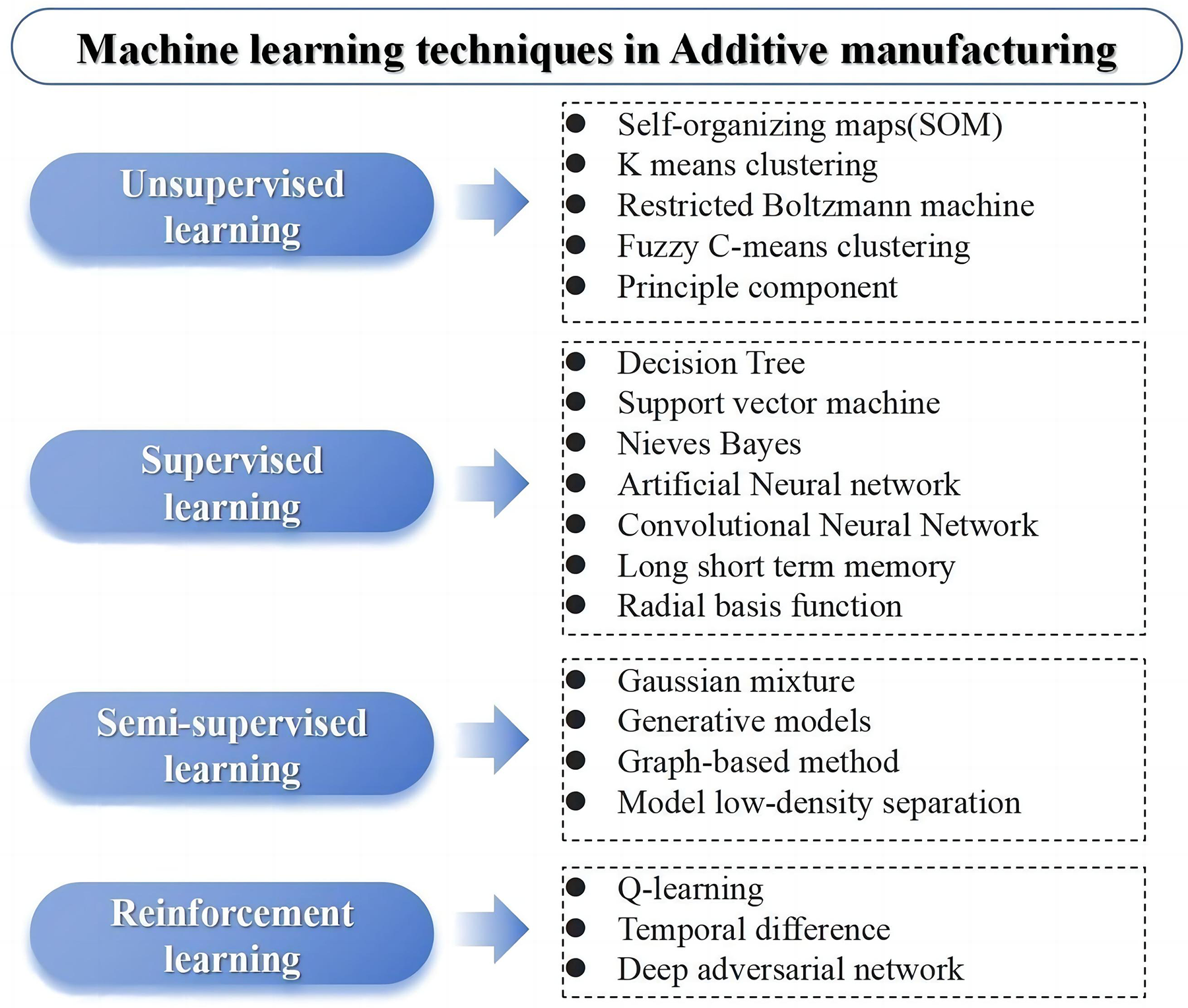
Machine learning techniques commonly utilized in additive manufacturing.
Supervised learning involves using a labeled training set to provide input values and corresponding outputs, making it suitable for classification and regression tasks. On the contrary, unsupervised learning automatically divides the training set into different clusters based on grouping parameters and identifies the target class, so it is primarily used for detecting abnormal conditions. Semisupervised learning only has labels for a portion of the training set, which is useful for problems with limited labeled data, so it can also be employed for classification and regression tasks. The current application of reinforcement learning in additive manufacturing primarily focuses on quality prediction using algorithms such as Q-learning (a kind of off-policy learning method, which can learn from the current experience, can also learn from the past experience, and can even learn from the experience of others). In the following, different machine learning methods used in monitoring data processing are introduced.
Monitoring data processing based on unsupervised learning
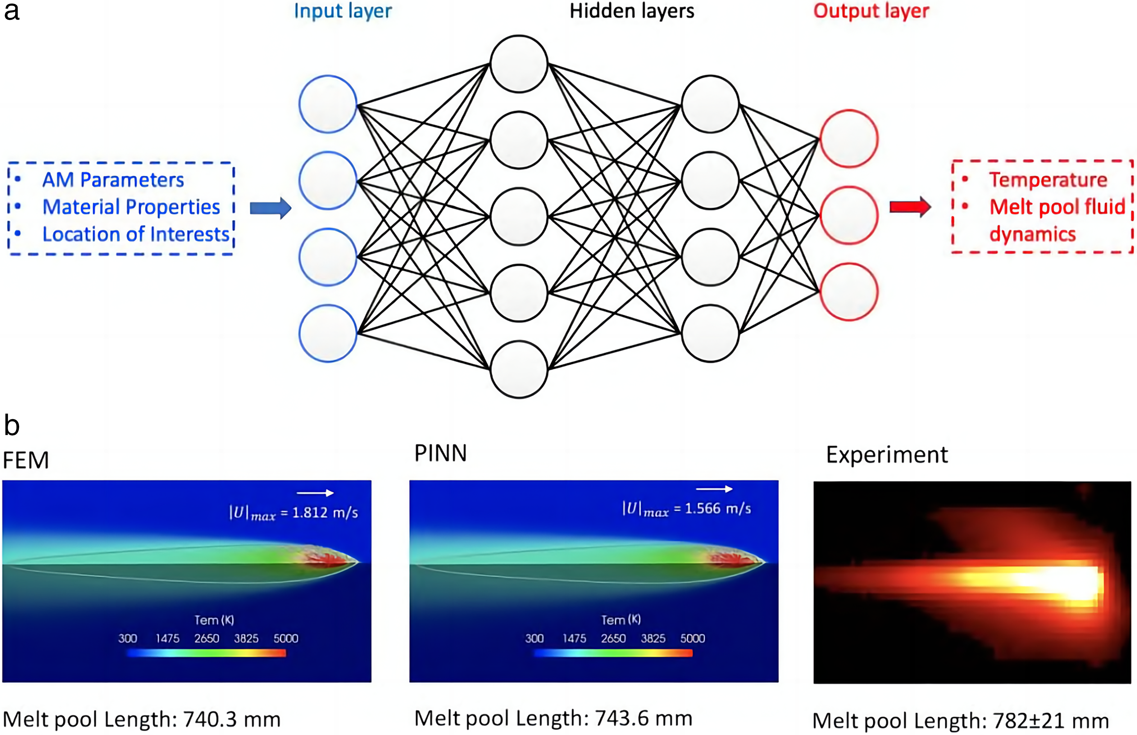
Unsupervised machine learning, also known as clustering, is an algorithm that groups data without prior knowledge of underlying data structures. Scime et al. 99 used machine learning to identify the characteristics of in situ molten pools formed by defects in the SLM process, computer vision technology to construct a scale-invariant description of molten pool morphology, and unsupervised machine learning to distinguish molten pool morphology. By monitoring the molten pool under various process parameters, the in situ characteristics are identified so as to realize in situ observation of defects. Snell et al. 100 employed unsupervised machine learning to classify small porosity and unfused porosity, achieving favorable outcomes. Zhu et al. 101 proposed a framework based on a physics-informed neural network (Fig. 9). This framework utilizes computer vision to monitor the morphology of the melt pool during the additive manufacturing process. It also employs unsupervised learning to identify and distinguish characteristics of the molten pool. By combining analytical data with physical principles such as momentum mass conservation, the framework can be used to accurately predict the temperature and dynamics of the melt pool. Silbernagel et al. 103 partitioned the optical images collected in the traditional parametric optimization process and applied unsupervised machine learning to evaluate the classification quality of the results. The findings demonstrated the effectiveness of machine learning in classifying monitoring results.
Monitoring data processing based on supervised learning
Supervised learning involves training a machine learning model using provided inputs and known outputs. One common application of supervised learning is image recognition. In image recognition tasks, a large dataset of images is provided for the machine algorithm, with each image having a corresponding label. By learning from these labeled images, machine learning models can predict the class of new images. This approach is particularly well suited for identifying and extracting features such as spatter morphology and molten pool morphology.
Gobert et al. 63 developed an algorithm for in situ monitoring of SLM defects using supervised machine learning. They employed high-resolution cameras to capture images of each layer of the object under study. Subsequently, they utilized linear support vector machines to analyze the images and extract various visual features. These features were evaluated in multiple dimensions to gain a deeper understanding of the characteristics of each layer. To determine the precise position of the defect, 3D computed tomography data were employed in training the support vector machine. Binary classification was then conducted, resulting in an accuracy of over 80% for in situ defect monitoring.
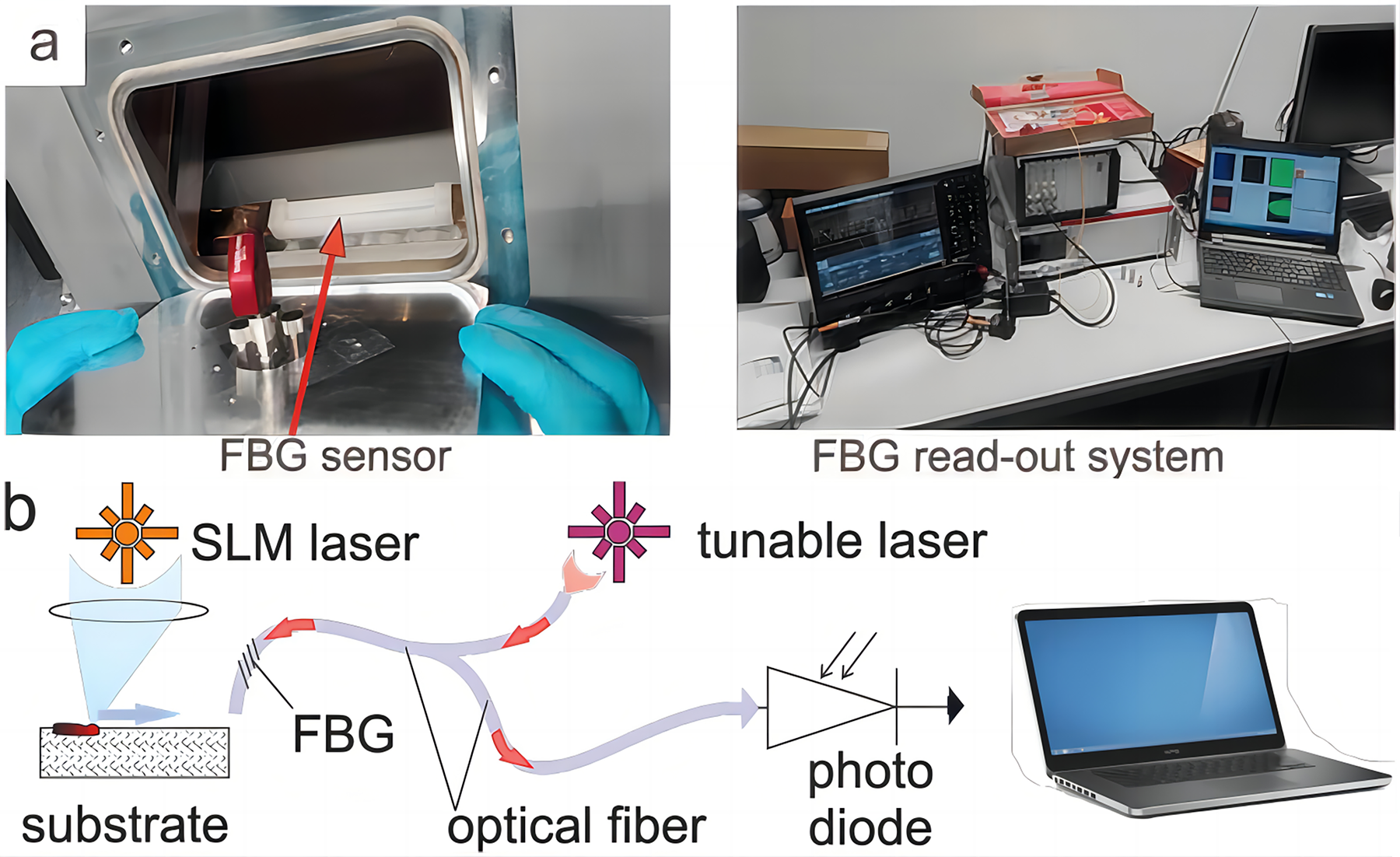
Shevchik et al. 104 employed fiber grating sensors to record acoustic signals during the production process of low-, medium-, and high-quality parts. They utilized wavelet packet transform to extract narrow-band energy as acoustic characteristic images and employed spectral convolutional neural networks (CNN) as classifiers to classify acoustic characteristics of different qualities. The results indicated that the classification confidence of the classifier ranges between 83% and 89%.
Yuan et al. 105 conducted a study on analyzing video data of the molten pool in the SLM process. They utilized the average value and standard deviation of the width of a single weld bead to examine the characteristics of the molten pool. Additionally, they also considered whether the weld bead was continuous or not in their analysis. In their research, a CNN was trained using a subset of the marked data to predict the width and standard deviation of the weld bead. The correlation coefficients for width and standard deviation were determined to be 0.93 and 0.70, respectively. Moreover, the accuracy of predicting the continuity of the weld bead reached 93.1%.
Aminzadeh and Kurfess 64 implemented an online monitoring system to evaluate the fusion quality and detect defects in the SLM process. They employed a Bayesian classifier to train and test the system. The results demonstrate the system’s ability to correctly identify fusion in each layer. In areas where the quality is low or defects are present, the system achieved a true positive rate of 89.5% and a true negative rate of 82%.
Coeck et al. 96 established a correlation between the melt pool signal, observed through two photodiodes, and unfused defects. They predicted the size and location of unfused pores and verified it through computed tomography. The results demonstrated the prediction accuracy was 90% when the pore volume exceeded 0.001 mm3.
Li and Anand 106 proposed a neural network-based method to predict the inherent strain of parts with arbitrarily filled patterns. They obtained the inherent strains of two different filled patterns through thermomechanical simulation and used the data from one pattern to predict the reverse direction using a trained propagation neural network. The results showed that the network can rapidly predict the inherent stress of any filled pattern with an error of less than 8%.
Ren et al. 102 conducted a study using finite element models to generate training data. They then developed a thermal analysis model that utilizes recurrent neural networks and deep neural networks. The aim of this model was to establish a correlation between laser scanning patterns and their corresponding output temperature fields. The researchers found that the thermal analysis model was successful in accurately predicting the temperature field of various geometric shapes when different laser scanning modes were used. The prediction accuracy of the model was reported to be over 95%.
Ye et al.107,108 collected acoustic signals during the SLM process using the 3780C1 PCB microphone. They utilized the deep belief network algorithm to establish the relationship between four different powder melting states and acoustic signal intensity. Additionally, they established the relationship between different degrees of defect states and process parameters. Chen et al. 109 proposed a supervised machine learning method to predict travel defects and printing performance in the SLM process. The experimental results are extracted and calculated to create a dataset used for training the machine learning model. This trained model can detect defect travel and predict the quality of SLM parts, providing guidance for process optimization.
Monitoring data processing based on semisupervised learning
Semisupervised learning is a significant topic in the field of pattern recognition and machine learning. It is a learning approach that is a combination of both supervised and unsupervised learning methods. By utilizing a combination of labeled and unlabeled data, semisupervised learning enables pattern recognition tasks. The aim of the semisupervised learning technique is to minimize the human effort required while achieving relatively high accuracy, and its importance has been increasingly recognized and acknowledged.
Okaro et al. 110 introduced a novel approach for the automated detection of defects in additive manufacturing products using a semisupervised machine learning algorithm. The researchers employed stochastic singular value decomposition as a means to extract significant features from the data acquired by photodiodes. This technique allowed them to identify key elements that contribute to defect detection. To further enhance the performance of their model, they then trained a Gaussian mixture model, which could be used to effectively identify defects in the manufactured products. The results demonstrated that the outcomes achieved with this algorithm are comparable to supervised learning while reducing costs.
To mitigate the reliance of existing data-driven methods on a substantial amount of high-quality labeled training data, Li et al. 111 introduced a semisupervised training data mining approach based on recognition consistency. They employed deep CNN for training and testing, and the experimental results indicate that good classification results can be achieved even with a small amount of low-quality data.
Yuan et al. 112 conducted experiments to gather a dataset of over one thousand SLM videos. They measured the physical output of these videos using height map images and applied a proposed image processing algorithm to generate a dataset suitable for semisupervised learning. CNNs were then trained to identify desired quality metrics from the videos. The experimental results validate the effectiveness of the monitoring approach and demonstrate that the semisupervised model can reduce the time and cost associated with labeling an entire SLM dataset.
Monitoring data processing based on reinforcement learning
Reinforcement learning algorithms differ from other machine learning in that they rely on training data that indicate correctness rather than providing labeled data. These algorithms learn optimal behavior through interaction with their environment, receiving positive rewards or negative punishments based on their actions. The feedback mechanism reinforces the model’s behavior, hence the name reinforcement learning. 113
Reinforcement learning algorithms often use the terms exploration and exploitation. Exploitation refers to taking action that produces the highest possible reward, and exploration refers to taking action that has not been taken before. By using a combination of these two techniques, the model can slowly learn more about the environment while understanding inputs that lead to positive rewards, hence arriving at optimal solutions.
Wasmer et al. 114 proposed a reinforcement learning approach for in-situ quality monitoring in additive manufacturing through the utilization of acoustic emission technology. By leveraging this method and employing acoustic emission data as a quality indicator, the research successfully achieved manufacturing at three distinct quality levels by adjusting various process parameters. Through the analysis and classification of acoustic emission signals, distinguishing features corresponding to different quality levels were identified. This study showcases the significant potential of the proposed method for real-time monitoring of additive manufacturing quality.
Machine learning has proven to be highly advantageous in processing one-dimensional and two-dimensional signal data, making it well suited for real-time feature extraction and defect identification in SLM process monitoring. The effectiveness of machine learning models greatly depends on the availability of training data, which is a crucial factor. Machine learning-based SLM process monitoring plays a fundamental role in intelligent monitoring and control and has become a prominent field of research.
Conclusions and Prospects
This article provides a comprehensive analysis of the defects in the SLM process, the types of monitoring signals, and the intelligent monitoring technologies associated with these signals. The common defects in the SLM process and their formation processes are also examined in detail. The optical, thermal, and acoustical signals generated during the process are described, with a summary of the relationship between these signals and defects. This article discusses different sensors commonly used for monitoring the SLM process and their collected signal characteristics. Additionally, it presents an overview of signal processing methods and analyzes the application of machine learning methods in SLM process monitoring. In conclusion, despite the substantial advancements made in monitoring and processing signal data within the SLM process, there are still many difficulties to be addressed in the real-time monitoring and controlling of defects in the SLM process toward obtaining the ideal quality of SLM parts. What follows are some potential avenues of research to address these difficulties:
The quantitative relationship between signal and defect still poses significant challenges. Many researchers have extensively utilized a range of sensors, encompassing sound, light, and heat, to establish a qualitative correlation between monitoring signals and defects. Before establishing qualitative correlation, however, it is still necessary to enhance the precision of monitoring sensors and the collection of signals. In order to improve the accuracy of monitoring sensors and signal collection, factors interfering with the monitored signals must be suppressed or eliminated. While past studies have shown that interference factors can be minimized by optimizing parameters, it is still challenging to completely eliminate interference. On the contrary, it is imperative to attain a profound comprehension of defect formation on the part scale. The potential roles of laser beam characteristics (including but not limited to power, beam profile, beam size, and focal plane) along with thermal conditions (including temperature distribution, heat accumulation, and dissipation within the part) and environmental gas flow (with emphasis on impurity level, flow speed, and flow pattern) over the entire build area should not be overlooked. Consequently, extensive research endeavors are crucial for understanding the impacts of these variations and their interrelationships, which can be used toward effectively predicting defects in additive-manufactured parts. The application of machine learning in the SLM process is a significant direction of future research. The use of machine learning in the SLM process covers a wide spectrum of applications, ranging from process optimization to in situ monitoring. Machine learning has been demonstrated to be a powerful tool for performing data-driven numerical simulation, optimization of process parameter, real-time defect monitoring, performance evaluation and prediction, forming quality control, and design feature recommendations (Fig. 10). In the process planning stage, it is necessary and important to consider defect reduction and elimination in the parts. Setting the process path and parameters is crucial for ensuring quality control in the SLM process. However, there is a lack of research on real-time feedback control using monitoring signals, which necessitates further investigation. There is a pressing need for extensive efforts to be made in developing innovative strategies to reduce and eliminate harmful defects from SLM parts. It is anticipated that a better understanding of the mechanisms behind defect formation and the advancement of new in situ monitoring tools will expedite the discovery of new approaches to address detrimental defects in the SLM process. The aim of future research is to control the occurrence of defects. SLM technology has the capability to introduce defects in specific locations within a part, and contrary to popular belief, these defects are not always harmful; in fact, they can be strategically utilized to create patterned defects that give rise to novel properties. However, there is limited research exploring this, and the potential for breakthroughs lies in the collaboration between the manufacturing, materials, mechanics, and design communities. By emphasizing the design, optimization, and controlled generation of defects in the SLM process, new phenomena and applications can be discovered. Therefore, it is crucial for these disciplines to unite and work synergistically to fully unlock the potential of defect-based SLM technology.
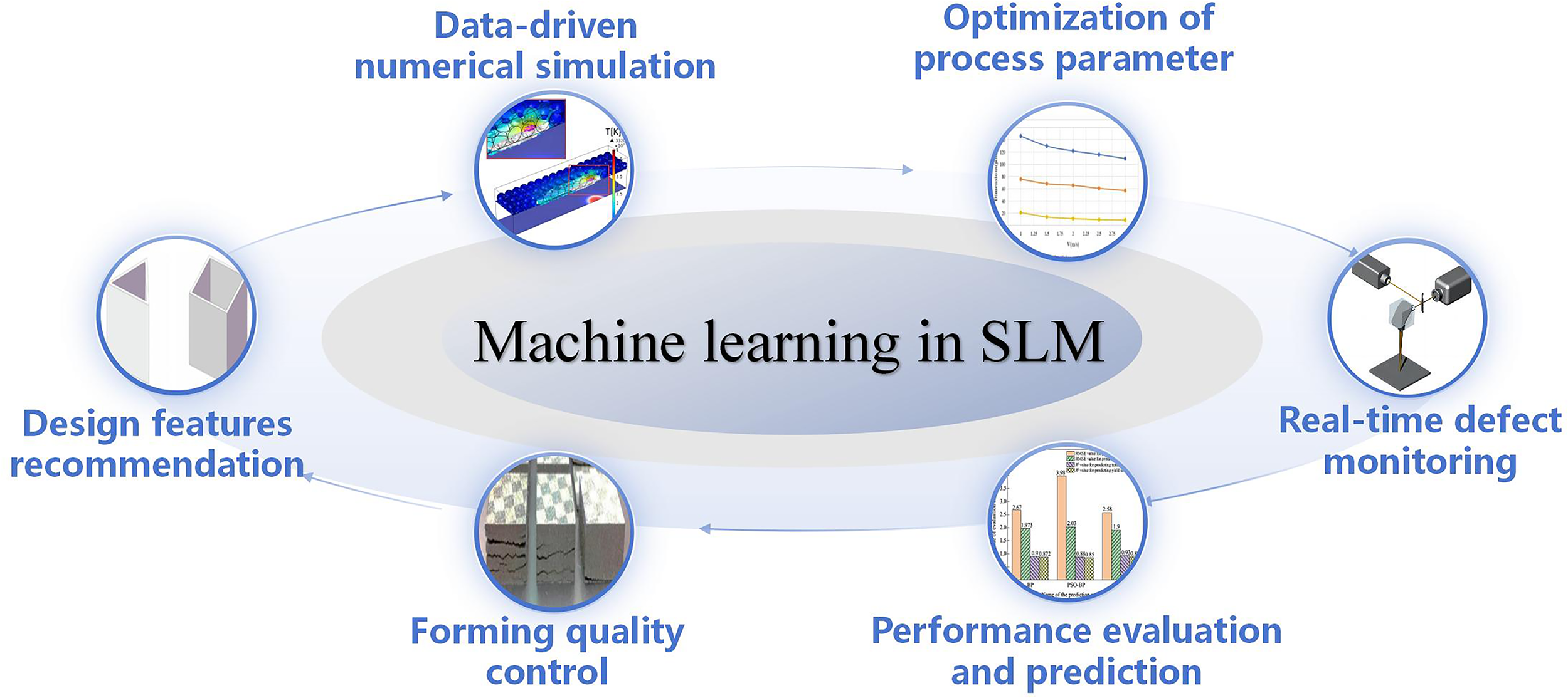
A summary of machine learning used in the SLM process.
Authors’ Contributions
Z.L.: Conceptualization, formal analysis, investigation, and writing. Y.Z.: Supervision, project administration, and funding acquisition. R.C.: Original draft preparation and editing.
Footnotes
Author Disclosure Statement
No competing financial interests exist.
Funding Information
This research was funded by the National Natural Science Foundation of China under Grant No. 62063010.