
Abstract
The current research studied the influence of plasma surface modification on the morphological and mechanical properties of 3D printed polyamide 12 composites. These composites were produced via laser sintering at three laser energies, 13, 17, and 21 W. Thus, the influence of the laser energies on the nanocomposites’ characteristics was also considered. The surface characteristics of the reinforcing materials, untreated and plasma-treated organically modified nanoclay, were characterized using Scanning electron microscopy (SEM) and X-ray diffraction. Furthermore, SEM was also utilized to investigate the fractured surfaces of 3D printed parts made from untreated and plasma-treated nanoclay/polyamide 12 composites after testing for measuring tensile properties (ultimate stress, strain, and elastic modulus). Based on SEM observations, agglomerated sheeted structures were observed in untreated nanoclay. However, these were relatively avoided after plasma treatment, and a more uniform distribution of nanoclay layers on polyamide 12 was observed compared with the untreated ones. This resulted in an improved elastic modulus of plasma-treated nanoclay/polyamide 12 nanocomposites when compared with these results for pure polyamide 12 and untreated nanoclay/polyamide 12 nanocomposites. These results, therefore, provide evidence of a successful combination of laser sintering and plasma treatment.
Introduction
Thermoplastic polyamide polymer is widely used as a matrix material due to its tuneable properties and excellent chemical characteristics as well as its acceptable price.1–3 Among polyamide matrices, polyamide 12 is considered a crucial polymer and one of the most frequently applied materials for polymer composites.4,5 However, its low mechanical properties against bending, impact, and fatigue are critical issues to be addressed. In order to overcome this issue, various methods have been applied. One of the useful methods that have been used is reinforcing the polyamide 12 matrix with stronger materials, either in the form of particles or fibers.6–8
Along with the significant developments in nanotechnology, the utilization of nanoparticles in reinforcing various polymer matrices is increasing rapidly. The utilization of these particles in polymer composites can significantly enhance the performance and functionality of the produced nanocomposites.9,10 However, different techniques exist for processing, testing, and implementing nanocomposite materials in various application industries. Depending on these factors, nanocomposites can be tailored to suit the specific applications of the aerospace, automotive, defense industries, biomedical and energy sectors, etc. 11 Nanoclay layers, among nanomaterials, have been widely used in polymer nanocomposites to improve the mechanical properties such as tensile and flexural strength.9,12 However, some studies suggest that nanoclay layers may have minimal or even negative effects on certain mechanical properties of the resulting nanocomposites when an excessive amount of nanoclay layers is used. 13 Nonetheless, these properties are highly dependent on how the nanoclay layers are dispersed within the polymer matrix. 14
Montmorillonite (MMT) is the most available form of nanoclay, 10 it occurs in nature in the form of platelets with an average thickness of about 1 nm and a width and length of up to 1 µm.9,15 The natural MMT comprises an octahedral silica sheet sandwiched between two tetrahedral alumina sheets to form the most familiar 2:1 structure. It is a hydrous phyllosilicate with a negatively charged layer caused by substituting silicon with aluminum in the tetrahedral layer and replacing aluminum with magnesium in the octahedral layer. The negative charge is neutralized by mineral cations such as sodium, calcium, or potassium, resulting in a regular stack of tetrahedral–dioctahedral layers. 12 However, MMT layers are inorganic fillers with hydrophilicity characteristics, making them incompatible with hydrophobic organic polymers. This results in poor interfacial bonding/interaction between polymer matrices and nanoclay fillers and consequently affects the final mechanical properties of the produced nanocomposites.16,17 Moreover, the stacks of nanoclay platelets are held tightly to each other by electrostatic forces, which further hinder the penetration of polymers or monomers into the nanoclay layers.14,18 Therefore, to overcome this issue, chemical modification of nanoclay layers is utilized to modify the hydrophilic clays by substituting the interlayer cations with organic cations.18–20 Although the surface chemical modifications of the MMT layers have improved the interfacial bonding between clays and polymer, 19 these treatments have been reported to be expensive and come with toxic chemicals.21,22 Therefore, an alternative eco-friendly surface modification process is of interest.
Plasma surface modification presents an attractive and environmentally friendly process for the treatment of various materials.23,24 If compared with chemical surface modification, plasma offers many advantages such as simplicity, short treatment times, low energy consumption, and hence low cost as well as it does not require liquid or any potentially hazardous chemicals.25–27 For continuous plasma processing, atmospheric plasma is preferable since it is produced at atmospheric pressure and does not need vacuum chambers or pumps like low-pressure plasma. 28 The effects of plasma surface treatment occur only on the top surface of the material, at the nano/micrometric scale, without affecting or altering the properties of the bulk. 27 Furthermore, the plasma process modifies the surface in a reproducible, controlled, and homogeneous way, so it can be used even in cases where the surface has an irregular geometry. 29 Therefore, the current study investigates the feasibility of using the plasma-treated nanoclay layers within polymer matrices (polyamide 12) via a laser sintering process to improve their mechanical properties. This process will allow for a more efficient use of the materials and the potential to create complex shapes and structures that can be used in a variety of applications. Thus, plasma modification was used to modify the surface properties of the nanoclay materials, while laser sintering was used to create the desired shape from plasma-treated nanoclay composites. By combining these two techniques, it is possible to achieve a more precise and reliable result than either method alone.
Materials and Methods
Materials
As a thermoplastic polymer matrix, polyamide 12 (in the form of powder) is supplied by e-Manufacturing Solution. It is a semicrystalline polymer, white in color, and odorless. The polyamide 12 powder used in this research was previously employed in the laser sintering process. However, the quality of the powder was still good, and for consistency, the same batch of polyamide 12 powder was utilized for all produced nanocomposites. MMT-based nanoclay layers (commercially known as nanomer I.34TCN) were used in this study as a reinforcing material. It was supplied by Sigma-Aldrich Chemicals (UK). Figure 1 represents the structure of the natural MMT as well as the structure and chemical formula of the organic surfactants that are used to modify the commercial organomodified nanoclay layers (nanomer I.34TCN). The essential mineral presence in these nanoclay layers is sodium montmorillonite with a chemical formula of [All.67 Mg0.33 (Na0.33) Si4Ol0 (OH)2], 31 and exchangeable sodium interlayer ions as shown in Figure 1a. The organomodified nanoclay layers, on the other hand, are obtained by exchanging the inorganic cations-Na+ with two different organic surfactants displayed in Figure 1b. The inclusion of the organic modifiers in between the nanoclay layers, shown in Figure 1c, will cause an increase in the basal space.

Plasma surface modification
Low air pressure plasma surface modification was carried out using Zepto plasma surface cleaner from Diener Electronic with a power supply frequency of 40 kHz and a cylindrical chamber made of borosilicate glass (size of 2.6 L). The as-received nanoclay layers (∼3–4 g) were first placed in very thin layers (∼1 mm thick) in a glass petri dish and then placed in the chamber of the plasma cleaner as presented in Figure 2. Thereafter, the parameters of the plasma cleaner were set as follows: power: 100 W, pressure: 0.3 mbar, treatment time: 30 min (in two steps), and process gas: ambient air. The topmost layer of the powder was first exposed to the plasma treatment for 1000 s, which turned brown. Thereafter, the petri dish was covered with another larger petri dish, and then both petri dishes were quickly flipped over to avoid the mixing of untreated and treated powder. In this step, the powder was transferred into the larger petri dish, and the untreated powder was on the top to be exposed to the plasma. The small petri dish was then lifted, and the large petri dish was then inserted into the plasma chamber to be treated for another 1000 s.
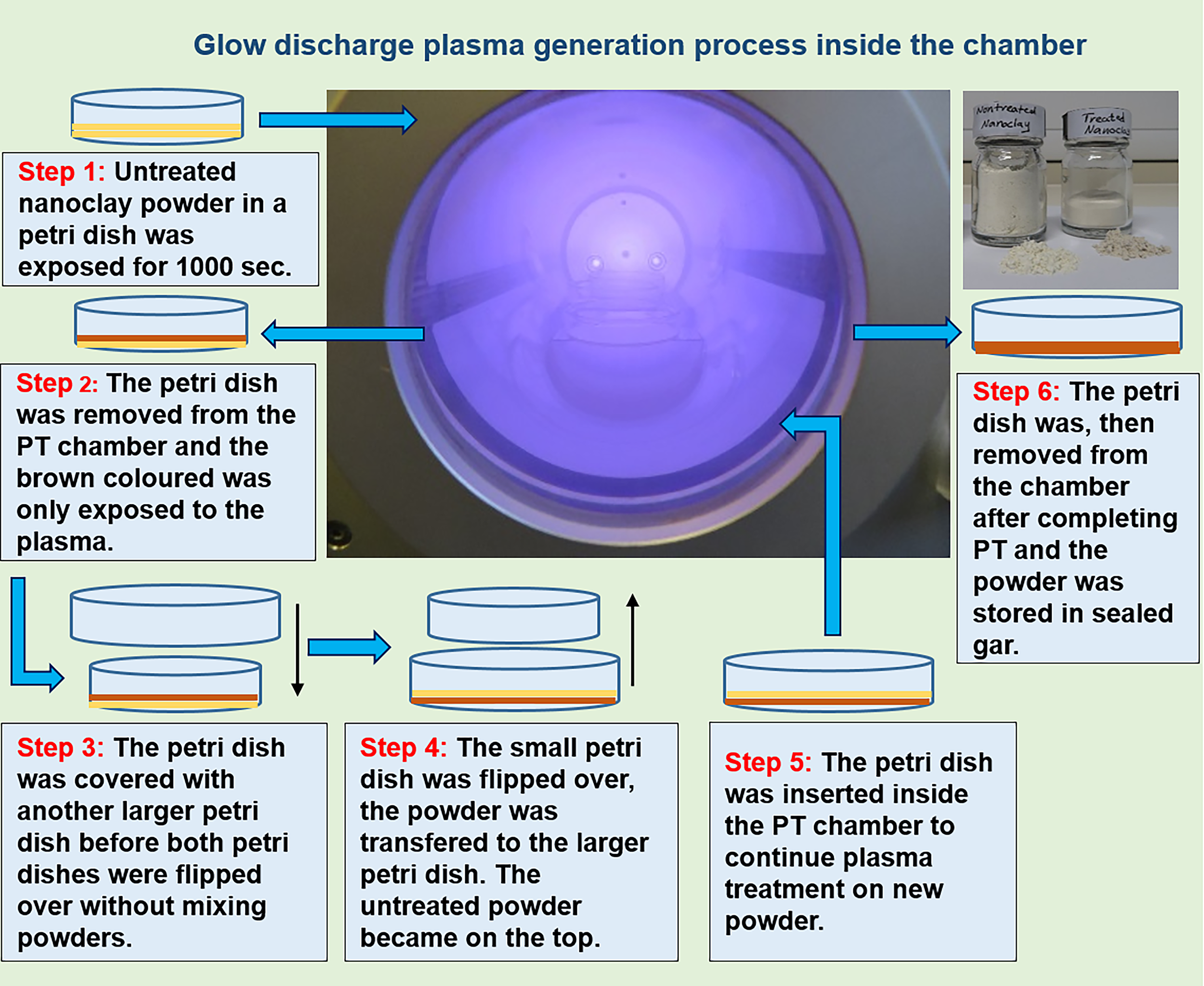
A designed representation of the steps of the plasma treatment process for nanoclay layers.
Composite fabrication
The untreated and plasma-treated nanoclay layers were first mixed in a glass jar with the polyamide 12 powder using a magnetic stirrer. The nanocomposite powders were stirred at a rotation speed of 800 rpm (36 g) for 30 min. Then, the powder was sonicated in an ultrasonic bath for 30 min to enhance the homogeneity of the mixed powders. Thereafter, Formiga P100 laser sintering from Electro Optical Systems (EOS) was used to fabricate the nanocomposite samples. In this process, the laser was generated under a nitrogen environment at a power of 13, 17, and 21 W with a bed temperature of 172°C, wavelength of 10.6 µm, speed scan of 2500 mm/s, scan spacing of 0.25 mm, and layer thickness of 0.1 mm. These parameters were used to ensure that the laser could provide the necessary power and speed to the material being sintered, while also controlling the temperature and ensuring that the layer thickness is accurate. Laser sintering is a mouldless process in which the laser light selectively fuses the preheated layered powder to create three-dimensional geometries. The fabricated samples were in the form of tensile test specimens. The content of untreated and plasma-treated nanoclay layers in the produced nanocomposites as mixed prior to the laser sintering process was 3% by weight. The 3 wt% nanoclay concentration for laser-sintered polyamide 12 demonstrated optimal results in Laser Sintering (LS) replication systems in terms of material integrity and process efficiency, leading to its selection. 32
Morphological observations
The tensile fractured surface morphology of the polyamide 12 and its nanocomposites was observed using FEI Nova Nano SEM 450. Note that no conductive coating layer was applied to the fractured samples prior to imaging. Therefore, in order to avoid surface charging, a very low accelerating voltage (1–2 kV) was applied. The micrographs were collected utilizing the Everhart Thornley Detector at a working distance of about 5 mm with 2 kV beam deceleration and 10−5 mbar vacuum pressure.
X-ray diffraction
The X-ray diffraction (XRD) of the untreated and plasma-treated nanoclay layers was performed using a Siemens D5000 diffractometer (Cu, GAXRD). The X-ray scans were performed at 40 kV and 40 mA in steps of 0.02° with a dwell time of 1 s per step. The collected data were analyzed using the DIFFRAC.EVA software from Bruker.
Tensile testing
A Tinius Olsen H5KS tensile testing machine with a maximum load cell of 5 kN was used to determine the tensile properties (ultimate stress, strain, and modulus) of the fabricated samples (polyamide 12 and its nanocomposites). The tests were performed at room temperature (22 ± 3°C) based on the standard ASTM D638-02a at a crosshead speed of 5 mm/min. The specimen dimensions are gauge length 25 mm; thickness 4 mm; width 6 mm; and the entire length is 115 mm. The tensile results were calculated using Horizon Software, and an average of six specimens per test condition was taken for each sample.
Results and Discussion
Surface morphology of untreated and plasma-treated nanoclay layers
The SEM micrographs of untreated and plasma-treated nanoclay layers are presented in Figure 3. It can be seen that in Figure 3a, the untreated nanoclay layers were aggregated to form large particles. These aggregated particles were round, oval, and irregular-shaped (highlighted by arrows in Fig. 3a) with a size of several microns. This could lead to poor dispersion within the polymer matrix. 33 However, after plasma treatment, the nanoclay layers tend to be smaller and less agglomerated (Fig. 3b) compared with those of untreated layers presented in Figure 3a. This could be attributed to the effect of plasma treatment. These effects were found to have a major role in determining the final mechanical properties of the produced composites (see Section “Tensile properties”).
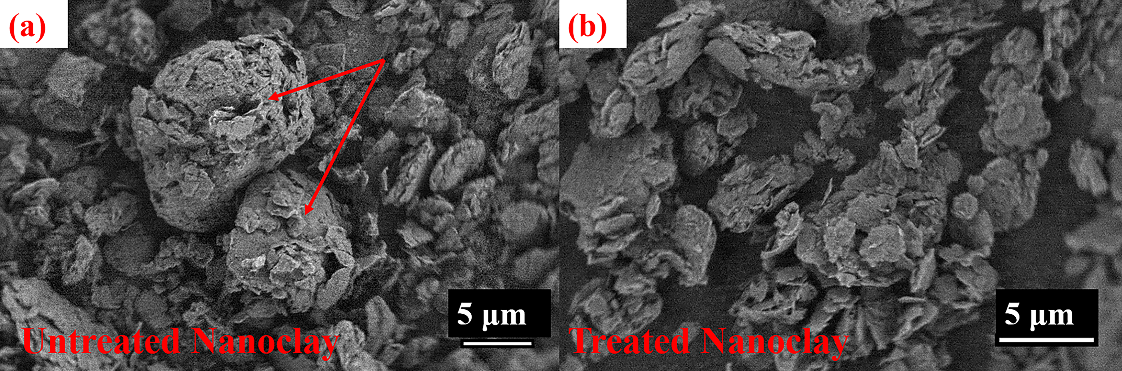
SEM images of
XRD of untreated and plasma-treated nanoclay layers
To further analyze the influences of plasma modification on the surface structure of nanoclay layers, XRD was performed. Figure 4 displays the XRD pattern of untreated and plasma-treated nanoclay layers. Both samples (untreated and plasma-treated nanoclay layers) showed peaks at 2θ of 19.7° and 2θ of 19.0° at higher angles. On the other hand, at low angles, the XRD patterns of untreated and plasma-treated clays are slightly different. Untreated nanoclay layers showed a characteristic intense peak at 2θ = 4.8° corresponding to interlayer d = 1.8 nm, which indicates the intercalation of I.34TCN into the MMT interlayer, while the basal space for I.34TCN is 1.96 nm. 34 The other reflections in the interval 2θ = 18°−21° correspond to the NaMMT crystal structure. 35 The plasma pattern of treated nanoclay does not show any change in the interval 2θ = 18°−21°. It means that no changes in the crystal structure of the host matrix NaMMT. In the interval 2θ = 3°−7°, splitting of the amorphous peak and the appearance of a shoulder on the right side (second peak) are observed. This new second peak with 2θ = 6.2° corresponds to the new interlayer d = 1.4 nm.
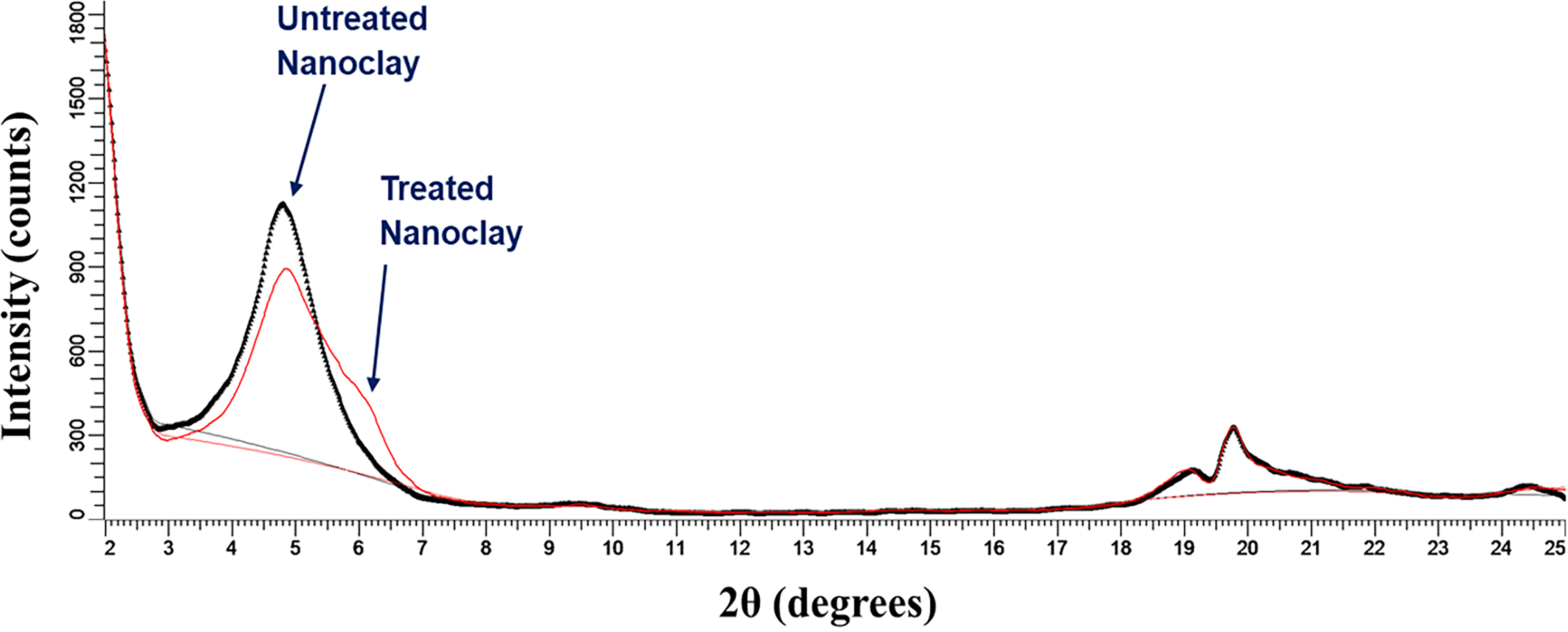
X-ray crystallography of untreated and plasma-treated nanoclay layers.
Based on the nature of plasma treatment (heat treatment), it can be assumed that the second peak (hump) and broadening are attributed to massive dehydration caused by plasma treatment. This suggests that the broadening of the XRD peaks for the treated samples indicates a loss of interlayer water, leading to a more disordered structure and inhomogeneous basal spacing. However, lowering the basal spacing and broadening of the XRD peaks are not solely attributed to dehydration. The observed changes in the XRD patterns can be caused by the combined effect of dehydration and dehydroxylation processes, which together contribute to structural modifications in the treated nanoclay powder. 36 The results of Fourier transform infrared spectroscopy (FTIR) and Thermogravimetric analysis (TGA) from our previous studies reveal this dual mechanism, with both dehydration and dihydroxylation.12,24 For example, the FTIR spectra indicated that the plasma caused a decrease and broadening of the O-H stretching vibrational band area between 3550 and 3200 cm−1 and a maximum at 3360 cm−1. Similarly, the intensity of the peak at 1116 cm−1 corresponding to the stretching vibrations of Si-O slightly decreased for the plasma-treated nanoclay sample. These findings reveal that the structural changes occurring in the plasma-treated nanoclay powder are a result of both dehydration and dehydroxylation processes due to the action of plasma treatment. 36 Furthermore, TGA results confirmed this dual mechanism, indicating successful dehydration and dehydroxylation. However, partial dehydroxylation was accompanied by the formation of new carboxyl groups by the carbon from the organic surfactant and hydroxyl groups at the surface of the clay layers. 12 These combined processes resulted in a disordered structure, which explains the observed XRD peak broadening and basal spacing reduction. However, optimizing the plasma treatment parameters, such as the time and power, is crucial for tailoring the desired structural modifications and enhancing the polymer/nanoclay performance in various applications.
Tensile fractured surface morphology
The tensile fractured surface morphologies of polyamide 12 and its nanocomposite, fabricated via laser sintering, are studied by investigating two different areas of each specimen, as shown in Figure 5. The top and bottom sections of parts made from polyamide 12 are shown in Figure 5a and b, while the top and bottom sections of those made by polyamide 12 nanocomposite with untreated nanoclay are shown in Figure 5c and d. Similarly, Figure 5e and f represent SEM images of the top and bottom sections of plasma-treated nanoclay/polyamide 12 nanocomposites. The SEM images in Figure 5a and b show some particles were not completely melted in the top and bottom surfaces of the fabricated parts (highlighted by arrows) but further down from the top and further up from the bottom toward the middle of the sample; a flat and relatively uniform surface was noticed which indicates that the layer-by-layer structure was successfully assembled. Moreover, enlarged pores surrounded by unmelted or partially melted particles were observed in Figure 5b (indicated by arrows). It is also noted that a larger crack was observed in the pure polyamide 12 specimen (Fig. 5a) (highlighted by arrows). The porosity and incomplete melting of PA12 particles prevalent in laser-sintered cross-sections have also been reported in previous studies.37,38

SEM micrographs of the tensile fractured surfaces:
The addition of nanoclay layers (untreated and plasma-treated clays) has modified the surface morphologies of the polyamide 12 composites (as shown in Fig. 5c–f), where relatively flat and uniform cross-sections were noticed. Cracks and micro-holes were also observed in Figure 5c and d (highlighted by arrows), which are attributed to the interlayer spaces or the voids generated by the adjacent particles that did not fuse completely. 39 However, the SEM images of the plasma-treated nanocomposites (Fig. 5e and f) reveal a more uniform surface morphology than those of untreated nanocomposites (Fig. 5c and d). Moreover, the former fracture surfaces of the plasma-modified nanocomposites have fewer unmelted/partly melted particles and smaller-sized micro-voids than the fracture surface of the composite with the untreated nanoclays. In addition, a large crack was observed in the fractured surface of the untreated composites (Fig. 5c, highlighted by arrows), which also had more pores than those in the plasma-treated composites. This probably indicates a better interaction between the plasma-treated nanoclay layers and the polymer matrix, which may facilitate the flowability of the sintered particles.
The individual unmelted particles in the plasma-treated nanocomposite specimen (shown in the high magnification SEM image, Fig. 6) were slightly fused together and became smoother and necks between some of the nonfused particles can also be seen. Some of the nonfused particles, however, were still rough, which may have been caused by insufficient energy supplied to the powder or a too low bed temperature. Agglomerated nanoclay layers can be easily seen on the surface of the unmelted polyamide 12 particles (marked by an arrow in Fig. 6).
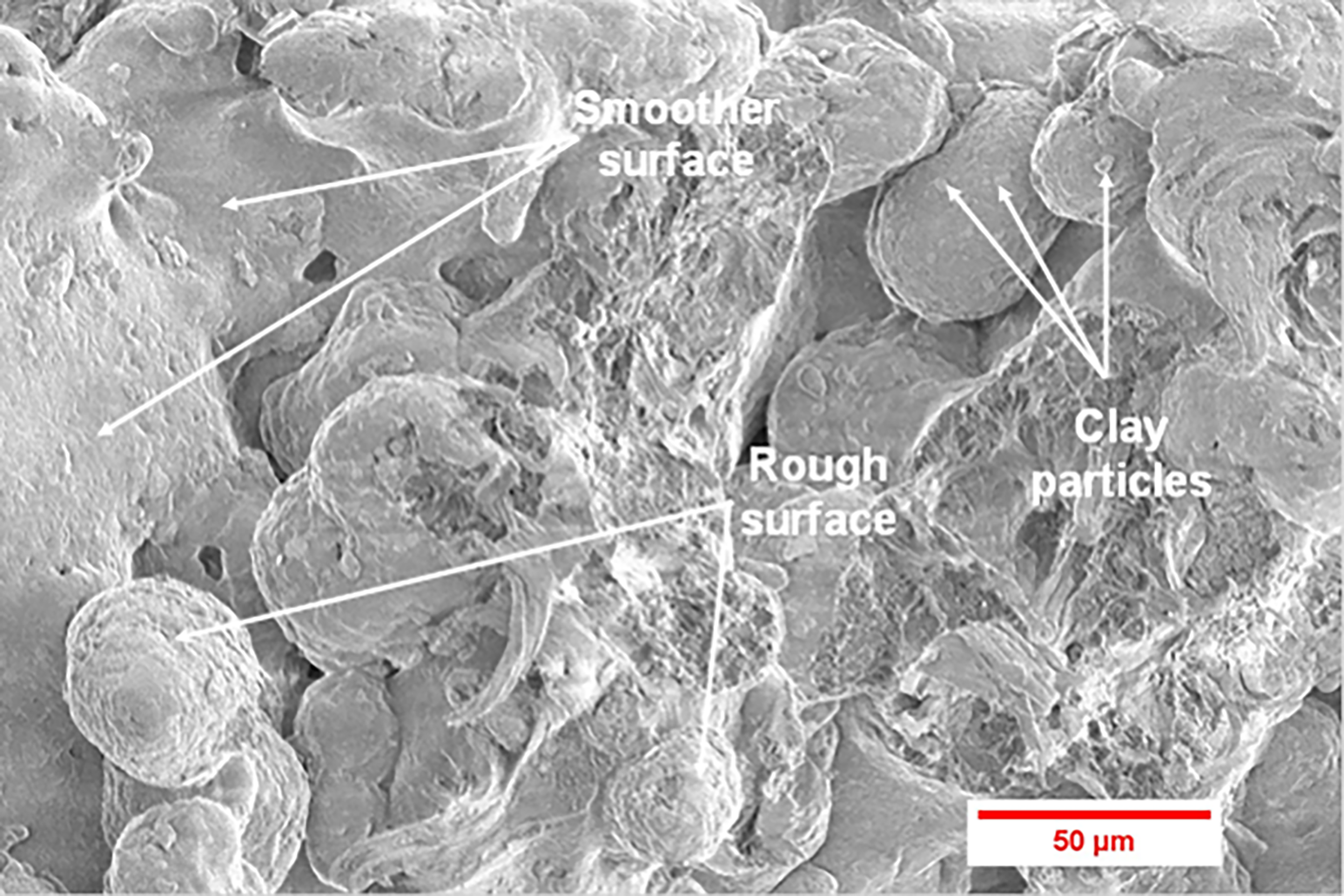
SEM micrograph of the tensile fractured surface of the plasma-treated nanoclay/polyamide 12 composite.
Tensile properties
The tensile properties (ultimate stress and ultimate strain) of the pure polyamide 12 and its nanocomposites (untreated and plasma-treated 3 wt% nanoclay/polyamide 12) fabricated using a laser sintering process at three different power energies (13, 17, and 21 W) are presented in Figure 7. The detailed results of the tensile tests, including the ultimate stress, ultimate strain, and elastic modulus results, with standard errors are presented in Supplementary Table S1. It can be seen from Figure 7a that the ultimate stress of polyamide 12 increases directly proportional to the amount of applied energy during the laser process. This can be attributed to the fact that, when power levels increase in the laser, energy delivered to polyamide 12 particles increases, leading to increased bonding between particles. 40 As a result, the material’s structure becomes more densely packed, increasing the ability and strength of the polyamide 12 to withstand stress.
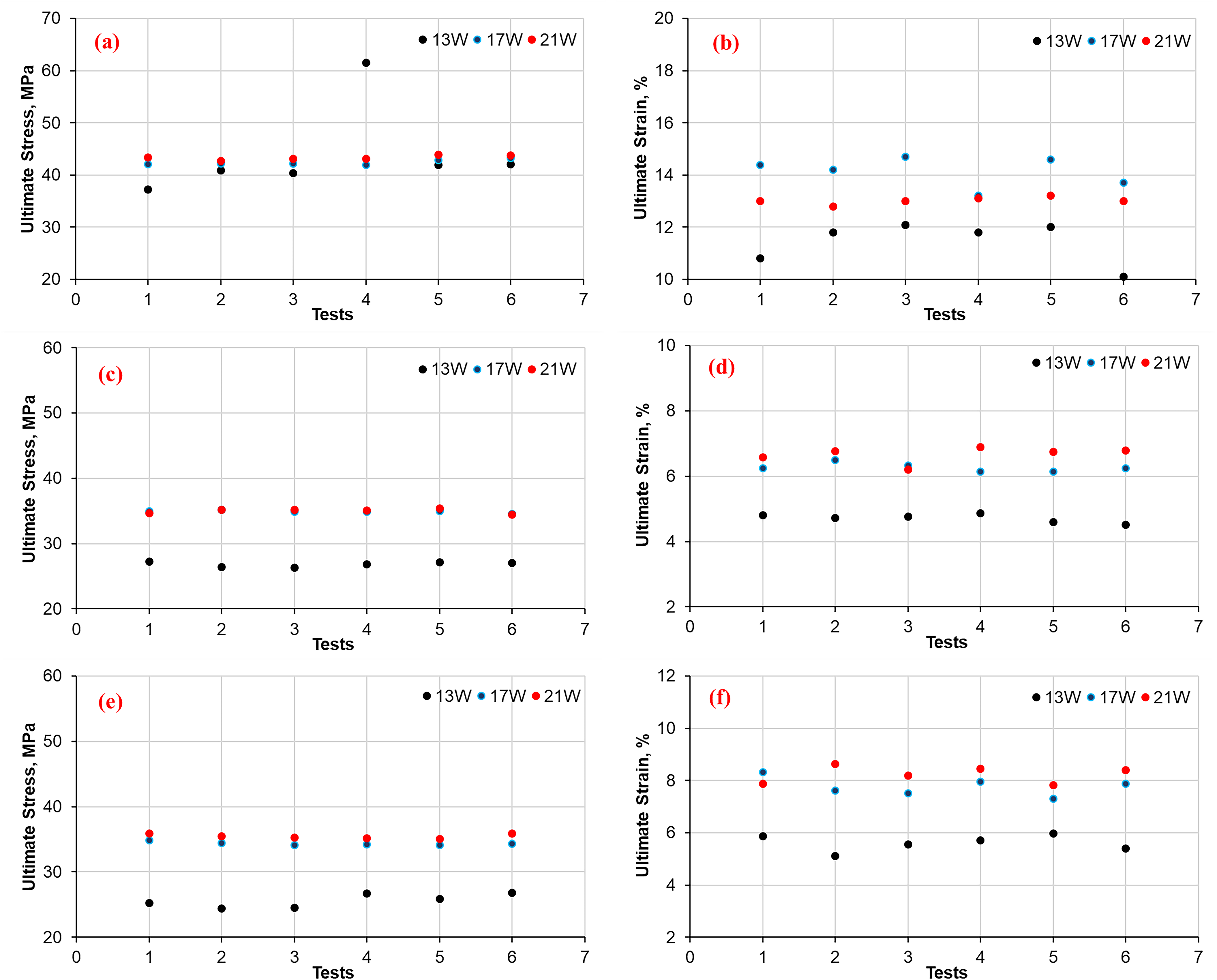
The tensile results (ultimate stress and ultimate strain) of polyamide 12
On the other hand, Figure 7b displays the ultimate strain (the maximum deformation a material can undergo before breaking) of the polyamide 12 fabricated using three different laser power energies (13, 17, and 21 W). From this graph, the ultimate strain of polyamide 12 increases as the power energy increases from 13 to 17 W due to the interfacial bonding increase between particles. This leads to an increase in the part density and particle fusion. However, interfacial bonding between particles increases with increasing laser power, which correlates with the degree of laser exposure to the powder particles. Thus, when the laser power energy is 21 W, an excessive laser exposure is delivered to the polyamide 12 particles. This results in degrading powder particles, deteriorating material properties, and lower ultimate strain obtained. 41 Therefore, the increase in laser power enhanced the tensile properties of polyamide 12 without sacrificing elongation at break. The low spread in ultimate stress indicates that the manufacturing process can lead to polyamide 12 materials that are consistent in strength. According to ref. 42 , a low spread in polyamide 12 indicates that the material’s semi-spherical morphology and particle size suit the laser sintering process. Meanwhile, the high spread in ultimate strain indicates that the manufacturing process can produce a polyamide 12 material with more variability in its ability to break or deform.
However, the ultimate stress of the untreated nanoclay composites (Fig. 7c) increased significantly as the laser power energy increased from 13 to 17 W, but at 21 W, no or limited increases occurred. A similar trend was observed in Figure 7d, as the ultimate strain of untreated nanoclay composite increases with increasing laser power reaching its maximum value at 21 W, but with only a little increase between 17 and 21 W. The combined effect of the undistributed nanoclay layers within the polymer matrix and the weak bond between polyamide 12 particles that occurs at low laser power, i.e., 13 W, lowers the values of ultimate stress and strain as observed in Figure 7c and d. When an untreated nanoclay composite is subjected to high laser power, the energy density is increased, which is directly correlated to the laser power. With the presence of nanoclay layers within polyamide 12, the increase in energy causes localized heating that improves the powder fusion and minimizes porosity, thereby increasing its ultimate strain before breaking or deforming and strength. However, at a higher energy density (e.g., resulting from 21 W laser power in Fig. 7c and d), the ultimate stress and strain increased to a very limited extent. This results from the fact that excessive laser exposure will lead to the degradation of polymers, causing increased porosity by trapped gases. 43 This suggests that the nanoclay can provide an increase in ultimate stress up to a certain point. Beyond that, the addition of nanoclay layers does not provide additional improvements. Thus, the trend in untreated nanoclay composites depends on the materials used in the reinforcement, processing condition, and matrix of the materials in the composite.
When comparing the ultimate stress and strain results for polyamide 12 presented in Figure 7a and b and untreated nanoclay composite in Figure 7c and d, the graphs illustrate that the strength was not improved and the strain was decreased. The reduction in strength of untreated nanoclay composite indicates poor dispersion and agglomeration of the untreated nanoclay layers, which weaken the mechanical properties of the resultant composite. 40 The agglomeration of the nanoclay layers within the polyamide 12 matrices could act as stress concentrators. These layers can cause premature failure or reduce the strength of untreated nanoclay composite. 44 Additionally, the agglomeration of the untreated nanoclay does not toughen the polyamide12 correctly, leading to a reduction in strain, making the material brittle and lowering its strength. 45 Similar trends were observed in Figure 7e and f, which display the ultimate stress and strain for the plasma-treated nanoclay composite. In Figure 7e, the ultimate stress increases with the increased laser power from 13 to 17 W, but it decreases when the laser power increases from 17 to 21 W. The observed increase in the ultimate stress with the increase in the laser power from 13 to 17 W could be attributed to the better interfacial bonding between polyamide 12 particles and nanoclay layers and also due to localized heating. However, the correlation between laser power and stress is not validated at higher laser power (21 W) due to the polymer degradation caused by excessive laser exposure. In Figure 7f, the ultimate strain increases with the increased laser power up to 17 W. When the laser power further increased, a stiffer and more brittle material was obtained that could break without deformation.
When comparing the ultimate stress and strain results for untreated and plasma-treated nanoclay composites, the graphs illustrate that the strength of the treated composite was improved compared with the untreated one. Plasma treatment is a modification technique that improves dispersion and interfacial adhesion between polymer matrix and nanoclay. 21 In the treated nanoclay composite, the plasma treatment has improved nanoclay dispersion resulting in a homogenous material with few agglomerates. As a result, the improved interfacial adhesion between the polymer matrix and nanoclay increases the load transfer capacity, thereby improving stress or strain between components compared with the untreated one. The increased spread of the measured values is possible in the treated nanoclay composite since plasma treatment improves variability in the measured mechanical properties, especially when the treatment process is uniform throughout the material. 21
Interestingly, the elastic modulus (shown in Fig. 8) was obtained by testing polyamide 12 and composites’ samples were produced via LS at three laser powers, i.e., 13, 17, and 21 W. By testing polyamide 12, the graphs in Figure 8a demonstrate that the elastic modulus increases with the increase in the laser power from 13 to 21 W, but the trend is not consistent due to the variation in the obtained results. Furthermore, the elastic modulus increases to a certain level and then drops, suggesting that there may be an optimal laser power at which the elastic modulus is maximized. For untreated (Fig. 8b) and treated nanoclay composites (Fig. 8c), the values at 13 W increased, reaching a maximum value at 17 W before decreasing at 21 W. However, the impacts of untreated nanoclay agglomeration can also be indicated in the elastic modulus data. This can be clearly seen in Figure 8b, as the elastic modulus values of the untreated composite were dropped to values below than those of polyamide 12 (Fig. 8a).
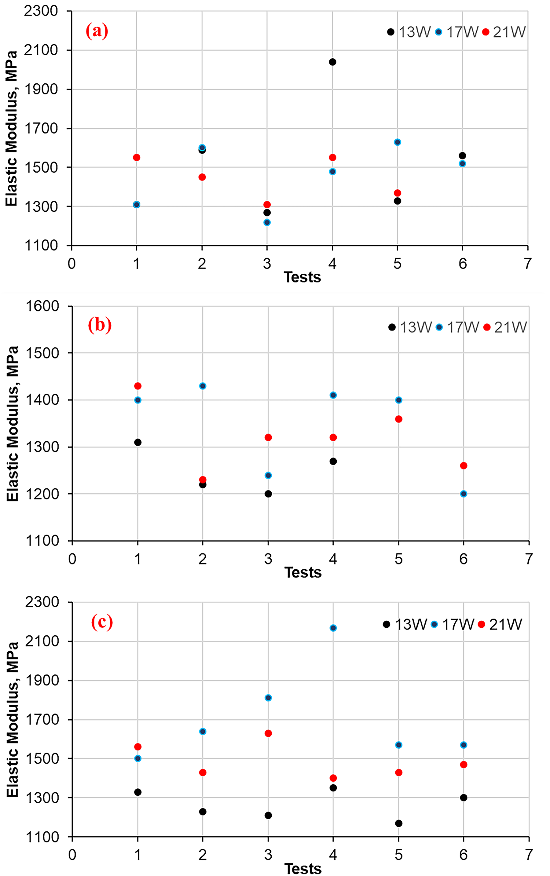
The elastic modulus of polyamide 12
Furthermore, the elastic modulus results of untreated composite tend to spread more due to the inhomogeneity distribution of nanoclay layers, in addition to the incompleted melt of particles and porosity. The treated composite showed improved elastic modulus results compared with the untreated composite and polyamide 12 results, as seen in Figure 8c. Furthermore, when comparing graphs in Fig. 8c with Fig. 8a and b, the results from elastic modulus have lower spread and more consistence results. This can be attributed to the chemical changes and the better distribution of the treated nanoclay within polyamide 12. Thus, it can be concluded that the plasma treatment process improves a composite’s mechanical properties, such as toughness and stiffness, and the strength was improved compared only with the untreated composite.
In addition to the encouraging mechanical properties obtained when including plasma-treated nanoclay (over untreated and polyamide 12), no significant deterioration in processibility was observed—complex LS parts could be produced when including the nanoclay as shown in Figure 9. This provides evidence of a successful combination of laser sintering and plasma treatment.
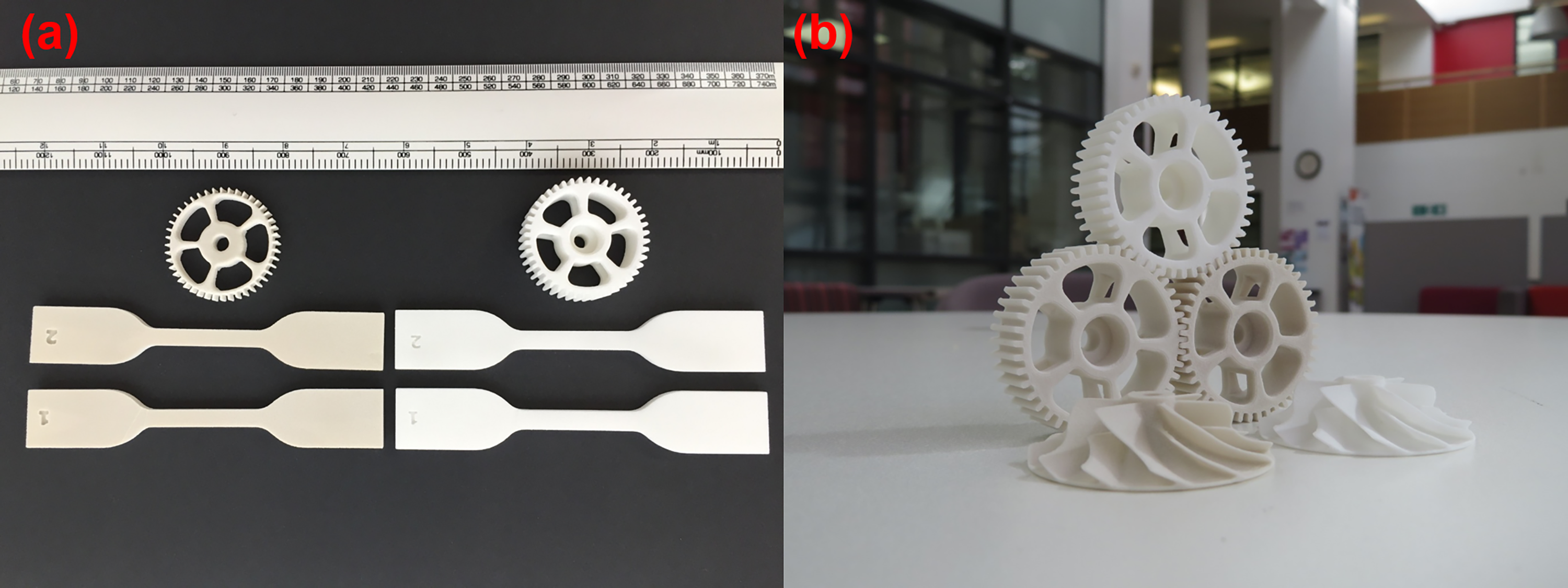
Photos of fabricated 3D printed objects by laser sintering:
Conclusions
Surface modification of nanoclay layers by plasma exposure enhanced the compatibility between the inorganic nanoclays and organic polyamide 12 materials in 3D printed objects fabricated by laser sintering. This modification suggests a notable change in the clay lamellar organization that affects the resonance vibration energy and, consequently, the spectrum. To verify this hypothesis, XRD results accompanied by a thorough analysis of SEM micro and nanostructures at different magnifications offered a good explanation for the surface and structure changes. XRD spectrum of the plasma-treated sample shows a broader and weaker band that can be attributed to increased disorder of the lamellae (disruption after treatment). The SEM morphological analysis demonstrated that sheeted structure, as well as clay layers and basal spacing between layers, were clearly observed for the plasma-treated nanoclay compared with the untreated one. Some mechanical properties of the laser-sintered samples demonstrate an improvement when including plasma-treated nanoclays if compared with those of untreated composites and pure polyamide 12 samples. The toughness of treated composites was higher than untreated but less than polyamide 12. However, the agglomerates in nanoclay (especially untreated nanoclay) create low reinforcements that cause a high spread of measured values and heterogeneous properties. Thus, in brief conclusion, a surface modification method using plasma for better powder distribution, combined with properly adjusted laser energy to avoid failed samples, resulted in producing successful 3D printed parts with complex and accurate shapes.
Authors’ Contributions
Conceptualization: A.A. Methodology: A.A., S.F.H., and W.A. Validation: A.A., S.F.H., and W.A. Investigation: A.A., S.F.H., and W.A. Resources: A.A., S.F.H., and W.A. Data curation: A.A., S.F.H., and W.A. Writing—original draft preparation: A.A., S.F.H., and W.A. Writing—review and editing: A.A. and S.F.H. Visualization: W.A. and S.F.H. Supervision: A.A. and S.F.H. Project administration: A.A. All authors have read and agreed to the published version of the article.
Footnotes
Author Disclosure Statement
The authors declare no conflicts of interest.
Funding Information
No funding was received for this article.
Supplemental Material
References
Supplementary Material
Please find the following supplemental material available below.
For Open Access articles published under a Creative Commons License, all supplemental material carries the same license as the article it is associated with.
For non-Open Access articles published, all supplemental material carries a non-exclusive license, and permission requests for re-use of supplemental material or any part of supplemental material shall be sent directly to the copyright owner as specified in the copyright notice associated with the article.