
Abstract
A system has been developed to electronically tag and track test tubes used in biorepositories. The system is based on a light-activated microtransponder, also known as a “p-Chip.” One of the pressing problems with storing and retrieving biological samples at low temperatures is the difficulty of reliably reading the identification (ID) number that links each storage tube with the database containing sample details. Commonly used barcodes are not always reliable at low temperatures because of poor adhesion of the label to the test tube and problems with reading under conditions of frost and ice accumulation. Traditional radio frequency identification (RFID) tags are not cost effective and are too large for this application. The system described herein consists of the p-Chip, p-Chip-tagged test tubes, two ID readers (for single tubes or for racks of tubes), and software. We also describe a robot that is configured for retrofitting legacy test tubes in biorepositories with p-Chips while maintaining the temperature of the sample below −50°C at all times. The main benefits of the p-Chip over other RFID devices are its small size (600 × 600 × 100 μm) that allows even very small tubes or vials to be tagged, low cost due to the chip's unitary construction, durability, and the ability to read the ID through frost and ice.
Introduction
R
A common method for tagging test tubes involves the barcode. One-dimensional (1D) and two-dimensional (2D) barcodes may be printed and applied, or may be etched or molded into a specimen container. Barcodes suffer from the requirement to be visible (no frost) and can be damaged by abrasion and chemical insults. In addition, some of the adhesives used on labels fail at low temperatures, especially if repeatedly exposed to temperature cycling.
Applications of radio frequency identification, or “RFID,” technology as an alternative to barcodes, have been developed for the storage of biospecimens. Several manufacturers offer RFID technology as a part of print-and-apply label systems for biospecimen sample containers used at low temperatures. RURO (Frederick, MD) and Zebra Technologies (Lincolnshire, IL) offer large adhesive label systems 3 in which desktop readers and a special adhesive label containing an embedded RFID device are attached to the exterior of each sample container. Integrity of the label under challenging conditions and the relative high cost of the RFID tag are serious concerns when implementing this type of system.
Recently, bluechiip (Scoresby, Victoria, Australia) introduced cryovials containing microelectromechanical systems (MEMS)-based tagtogether with custom readers. 4 Again, size and high unit cost of the tag are concerns.
Certain types of smaller test tubes are virtually impossible to tag with a typical, barcoded label or RFID tag. One example is a popular REMP STBR384 “nanotube.” 5 These 40 μL polypropylene test tubes, which can be arrayed into custom 384-position racks (DTBR384), are very small tubes (3.1 mm diameter and 19.1 mm length) that have not been addressed by any commercial labeling technology.
PharmaSeq has developed a tagging and tracking system for test tubes based on its light-activated p-Chip microtransponder 6 (Fig. 1). The PharmaSeq system is composed of p-Chip-tagged test tubes, storage racks, and accompanying ID readers with software that allows users to interface with existing biorepository enterprise database systems. Sample storage containers tagged with p-Chips overcome the limitations of other methods and, therefore, offer a solution that will save time and money and improve reliability in biobanks and other biomedical facilities.
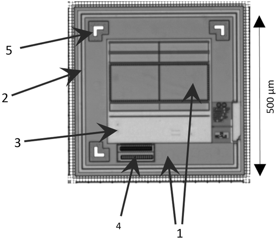
Photograph of a p-Chip. Key elements are (1) photocells; (2) antenna; (3) logic circuitry; (4) memory; and (5) registration marks.
Other p-Chip applications include small-animal (mouse) tagging (a commercial system is available),7,8 tagging of entomological collections, 9 studies of social behavior of ants and bees,10,11 as well as cell-based, DNA and immunology-based assays12–16 and synthetic genomics and proteomics.
The purpose of this article is to describe key properties of the p-Chip system for realizing improvements in biorepository sample management through tagging of cryovials. We will use, however, the generic term “test tube” to denote a plastic vial often used in many applications, a special case of which is a “cryovial.” This terminology is purposely chosen since the hardware and methods described in this article can be used in many biomedical settings, not just in biorepositories. The definition implies that ID readers (described in the Single tube reader and Array reader sections) designed to read “test tubes” can be used for “vials” and “cryovials” as well.
Materials and Methods
The p-Chip
The key component of the PharmaSeq biorepository system is the p-Chip—a small, durable integrated circuit that transmits its identification (ID) code when illuminated with modulated laser light (Fig. 1). p-Chips are highly stable over a broad temperature range of −196°C to more than 200°C, can be read through frost, and therefore are compatible with both sample container manufacturing and actual storage conditions.
The p-Chip is a unitary application-specific integrated circuit (ASIC) that transmits its ID code via radio frequency (RF). The actual dimensions of the chip are 600 × 600 × 100 μm, though the area occupied by the electronic circuits is less (500 × 500 μm) (Fig. 1). It is composed of photocells, logic circuitry, a loop antenna, and electronic memory. The 64-bit memory architecture is configured currently to provide over 1.1 billion possible ID codes. This “write once read many times” (WORM) memory stores the chip's ID. The photocells, when illuminated by a pulsed laser light from a dedicated ID reader, efficiently provide power and timing signals to the electronic circuits on the chip. The chip transmits its ID via modulated current in its antenna. The varying magnetic field around the chip is received by a nearby coil in the reader, analyzed, and decoded. The readout is fast (less than 10 ms). The actual transmission time of one data frame by the p-Chip is less than 1 ms. Custom software, “p-Chip Reader,” is used to display the ID on a computer screen (Fig. 2).
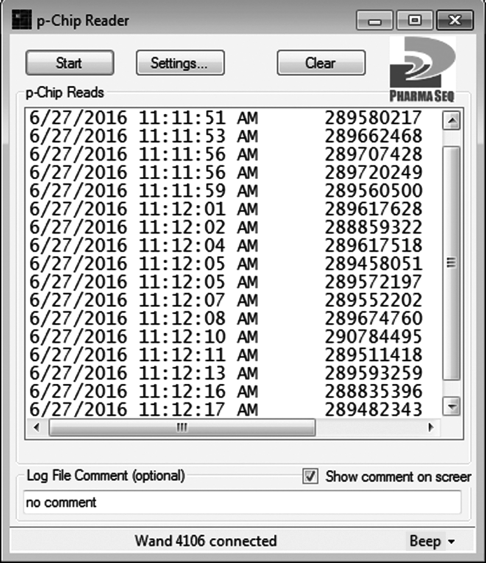
Screen shot of p-Chip Reader software window. Entries being shown are the date and time stamps and IDs of the reads. Parameters being reported can be altered using the “Settings” tab.
p-Chips are manufactured on silicon wafers in foundries, using standard, low-cost silicon complementary metal-oxide-semiconductor (CMOS) processes similar to those used in the manufacturing of computer processors. Wafers receive postmanufacturing treatment consisting of laser encoding (to set IDs), passivation, thinning, and dicing to yield individual p-Chips. The IDs are predetermined by the manufacturer (PharmaSeq) and are encoded sequentially as new p-Chips are made. The p-Chip surface is made of silicon nitride, which is deposited as a final passivation layer for abrasion resistance.
The strength of the RF signal emitted by p-Chips is not affected by exposure to temperatures significantly higher than 162°C, the melting point of polypropylene. This indicates that p-Chips will perform properly after they are embedded into melted polypropylene during the manufacturing process.
Testing procedures for p-Chips embedded in plastic or in a test tube
Two crucial parameters of success for biorepository cryovials are the ability to be stored at low temperatures for an extended period of time, and stability to repeated temperature shifts when the vials are removed from and replaced into freezers and Dewar flasks. Both aspects are assessed here, first on p-Chips alone and then on p-Chip-tagged vials.
p-Chip arrays in plastic sheets
To simulate the environment of p-Chips embedded in a cryovial or test tube, grids (“arrays”) of 100 chips were sealed between two 0.03″ thick sheets of polypropylene by melting at 162°C in an oven (Supplementary Fig. S1; Supplementary Data are available online at www.liebertpub.com/bio). Following the oven treatment, all p-Chips were verified as readable before the array temperature was manipulated experimentally. p-Chips embedded inside of an array were always read with a PharmaSeq wand 8 as the configuration was not compatible with either a single tube reader (STR) or an array reader (both described in full below).
Long-term low temperature stability of p-Chip arrays
Four p-Chip arrays, each containing 100 chips, were stored in a −80°C freezer. An additional four arrays were placed in liquid nitrogen after having their temperatures reduced to −90°C via a standard cooling profile in a controlled rate freezer (Thermo Scientific CryoMed, Model 7450; Profile 2). This reduces the temperature by 1°C per minute from ambient to −40°C, followed by a drop of 10°C per minute to a −90°C end temperature. At specified time points (30, 90, 182, and 364 days) a single array was removed from each low temperate storage container. The arrays were allowed 6 hours to reach room temperature and the p-Chips were then read. After reading, each array was discarded from the experiment and not returned to the low temperature cohort.
Low temperature cycling stability of p-Chip arrays
A single p-Chip array containing 100 chips was placed in liquid nitrogen after its temperature was reduced to −90°C in a controlled rate freezer (Thermo Scientific CryoMed, Model 7450; Profile 2). After 24 hours, the array was removed from liquid nitrogen and allowed 6 hours to reach room temperature. All p-Chips were read and the liquid nitrogen treatment was repeated a second time. Again, the array was removed 24 hours later and the p-Chips were read.
Another p-Chip array containing 100 chips was placed into a −80°C freezer. After 24 to 72 hours, the array was removed from the freezer and allowed 1 hour to return to room temperature. The p-Chips were read and the array was replaced into the freezer. This cycle was repeated a total of 15 times over a 3-week period.
p-Chip chamber integrity testing of tagged cryovials
Testing of the structural integrity of custom molded cryovials (Isthmus Scientific, LLC, Middleton, WI) was performed to assess the presence of cracks, fissures, or channels leading into the recessed p-Chip chamber. The occurrence of small imperfections is relevant not only to the quality of the container, but overall safety as well. Rapid expansion of trapped, interstitial liquid nitrogen can potentially lead to an explosion and injury to a user. Ten test tubes were immersed in a Cy3 (Sigma-Aldrich) dye solution for 30 minutes and then quickly washed with dimethyl sulfoxide and immediately examined by fluorescent microscopy for presence or absence of the dye. As a control, holes were manually bored into three separate cryovials and exposed to the same dye visualization experiment.
Low temperature cycling stability of p-Chip-tagged cryovials
One hundred p-Chip-tagged cryovials (custom 1.5 mL vials; Isthmus Scientific) were immersed directly into liquid nitrogen and removed after 1.5 hours. The p-Chips were read with a “STR” (described in full below) after coming to room temperature for 2 hours, and the vials then placed back into the liquid nitrogen. This cycle was repeated a total of 10 times. Following the final cycle, the cryovials were left in liquid nitrogen for an additional 9 months and read again after returning to room temperature for 2 hours.
Readout of IDs of p-Chip-tagged vials at ultra-low temperatures
It is widely accepted that temperature fluctuations are detrimental to the long-term stability of biospecimens. Thus, having a tag that reliably functions on samples while they are still frozen is advantageous. To determine whether p-Chip IDs can be read at ultra-low temperatures (temperature readability) 20 custom molded cryovials (Isthmus Scientific) with embedded p-Chips were partially submerged in liquid nitrogen, keeping the chip temperature at −196°C. For reading the IDs, the box was brought to the surface of liquid nitrogen inside the dewer and the vials read with a wand. The wand was kept at room temperature (RT) before use.
Through-frost readout capability of p-Chips in comparison to 2D barcode
A layer of frost covering the surface of a p-Chip can impede photocell illumination, potentially impairing operation by reducing net power generated by the chip's photodiodes. Additionally, frosted vials are a common occurrence in the biorepository setting, requiring the user to remove any frost before reading its ID, or allowing partial thawing that potentially compromises the sample. Cryovials that can be read directly out of the freezer without requiring the physical removal of frost would clearly be advantageous.
Twenty-five p-Chip-tagged vials (Isthumus) were labeled with a 1D barcode cryogenic tag (GA International). The 25 dual-tagged vials, along with twenty-five 0.75 mL 2D data-matrix coded vials (Micronic), were filled with 500 μL of distilled water to aid in the acquisition of frost and stored at −80°C for 24 hours. Frost was then formed on the entire set by applying a stream of 37°C air with 100% humidity. After being removed from the freezer, the ID of each p-Chip was read with a PharmaSeq wand. The 1D and 2D barcodes were read with a standard commercially available scanner (Microscan HS-21). Vials were removed from the freezer individually to prevent the melting of frost before reading IDs.
Results
Single tube reader
The “STR” (Fig. 3) is a modification of the PharmaSeq Wand 8 with added components relevant for reading test tubes. The laser excitation elements, optics, receiver antenna, and amplifier all are enclosed within a specially designed “Laser Receiver Module (LRM)” with a Luer-lock fitting that accepts custom test tube-specific adapters, later referred to as “adapters” (Fig. 4). In the construction of the STR, the LRM is secured to the base of the STR assembly, the laser beam projecting upward toward the ceiling. An adapter, unique to each size of test tube being read and attached to the LRM, provides a positive guide so that a reliable read of a p-Chip-tagged test tube is accomplished. The presence of a test tube in the adapter's cavity area is detected by an infrared (IR) photointerruptor subsystem with an IR light-emitting diode (LED) shining across the adapter through holes cut in both sides of the adapter. When a test tube is present, the beam is interrupted. Removing the test tube signals the field programmable gate array (FPGA) to begin a countdown to beam cutoff. The laser beam is de-energized within 3 seconds of the test tube being removed. The laser used is registered with the FDA as a class 3R device, similar to a common laser pointer and does not require protective eyewear.
Design of the STR.
Adapter for 1.2 mL test tubes.
The STR, which is about the size of a large computer mouse (Fig. 3), interfaces via a USB cable to a computing device (PC, laptop, tablet) running Windows XP or any later version. The ID of each tube is reported sequentially and is fast (less than 10 ms per tube). The STR is designed to read a wide variety of commercially available sample tubes using one of a collection of adapters (Fig. 4) that are self-aligning and easily swapped out. The temperature operating range is −20°C to 35°C.
Software
“p-Chip Reader” software is a Windows-based program that controls ID readers. The program receives and processes the data from each test tube-embedded p-Chip as it is read. The software interfaces with firmware in the STR, which controls a FPGA that decodes the ID and, if desired, passes it to any program running on a Windows device. The ID can be displayed directly in the p-Chip Reader window (Fig. 2), and a simulated keyboard entry in desktop applications such as Microsoft Excel or Access for small collections or, alternatively, comprehensive enterprise laboratory information management systems (LIMS) for larger biorepositories. The specifications for the STR are listed in Supplementary Table S1.
Array reader
In constructing an array reader (Fig. 5) for p-Chip-tagged test tubes, we adopted PharmaSeq's existing ID reader platform. The array reader has been designed for a 96-position Society for Biomolecular Screening (SBS)-format box (8 × 12), the most popular format used in biorepositories. The design can be extended to other formats, such as 9 × 9 or 10 × 10 biorepository freezer boxes, through an engineering process involving a modification of the arrangement of p-Chip illumination/read locations. Work is ongoing in the design of a universal ID reader that will allow a freezer box of any configuration to be scanned by passing over a large, general read-area.
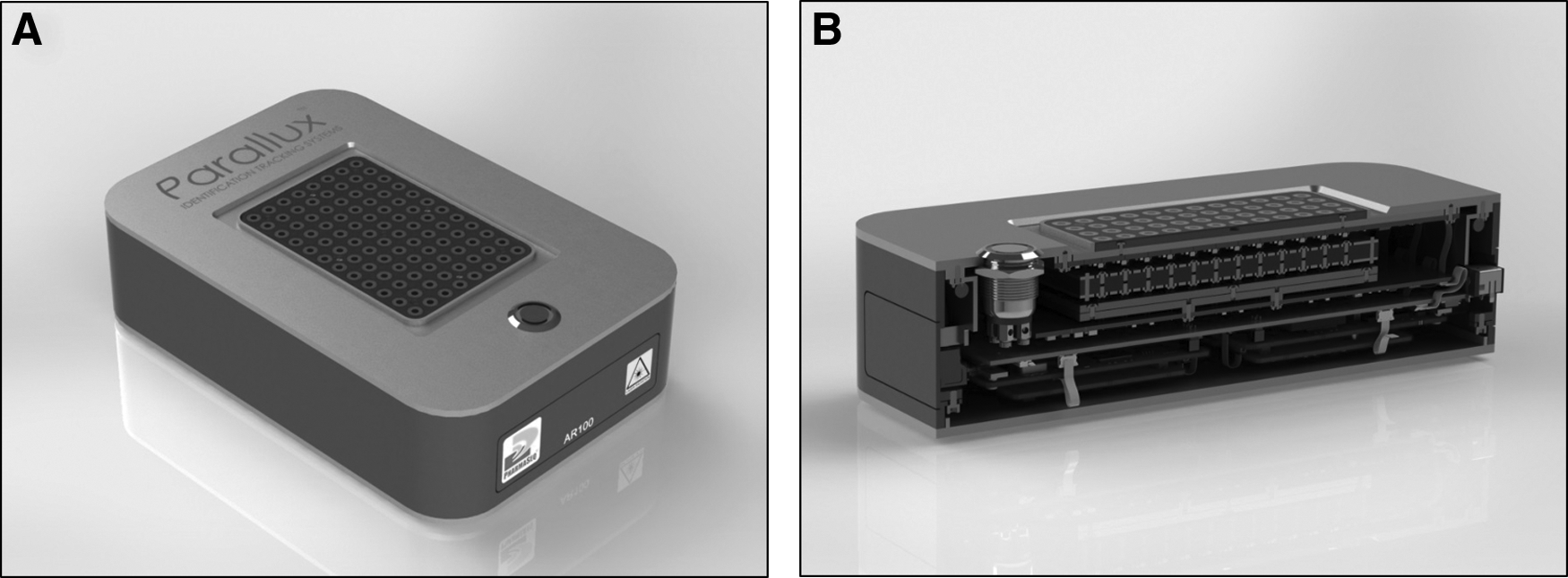
Array reader for racks of p-Chip-tagged test tubes.
The array reader design consists of an array of 96 discrete emitters, laser diodes, with acrylic light pipes to relay the light to the window separating the reader's optomechanics from the bottom of p-Chip-tagged test tubes suspended in an SBS-96 box. The SBS-96 box has an open bottom, facilitating optical access to the tagged test tube bottoms. Each of the 96 sites also has its own pickup coil positioned concentric to each test tube. This array of laser-optic-coil units is controlled by three printed circuit boards: an RF receiver array board, a laser driver array board, and a main control board with USB and power connectors that interface with an external computer and power supply. The main controller acts as a unifying interface and manages power and communications throughout the system. Overall dimensions are 9″ × 6″ × 2.4″ with a primarily all-aluminum construction and Gorilla Glass (Corning) window (the same as that used in smart phones). The temperature operating range is −20°C to 35°C. The design specification is for 96 test tubes to be read in 2 seconds or less to prevent sample thawing.
The benchtop unit (which can also be fastened to the bed of a robotic liquid handling system) is connected via USB to the PC/laptop/tablet with 24 V AC/DC desktop power supply. The unit includes a single button that functions as power on/off, wake, and execute scan. This functionality can also be initiated from the user interface (UI) on the computer. The UI also displays a graphical representation of an SBS-96 rack with sample information linked to each cell in a displayed array corresponding to each test tube once a scan is complete. For example, when clicking a cell occupied by a p-Chipped test tube, information such as p-Chip ID, sample description, and scan history is displayed. The UI is designed to facilitate linkage of the sample ID with enterprise databases. The UI is also used to check samples/racks in to and out of a biorepository. The system works with SBS-96 racks from most major manufacturers. The software is compatible with commonly used LIMS.
During a scan of an 8 × 12 rack of SBS tubes, the eight columns of the reader, in parallel, each execute a serial scan of the twelve rows. The scan time at each position is ∼100 ms, which results in a total scan time of 1.2 seconds per rack. If there are any missed reads, the scan will repeat a second time. This results in an overall scan time of 1–3 seconds. During the interrogation of a particular position, the laser diode associated with that location is turned on to activate the p-Chip-tagged test tube positioned ∼2 mm away from the array reader window for the 100 ms interval. The specifications for the array reader are listed in Supplementary Table S1.
Pick-and-place robot for tagging sample test tubes with p-Chips
We used a customized robot designed and manufactured by Electrosort Automation (Easton, PA) (Supplementary Fig. S2) to perform the pick-and-place procedures. The p-Chips are placed in a bowl feeder with a vibration mechanism, raised vertically and passed to a linear feeder, passed by an orientation detector, and conveyed to the end of a track for pick up. If the orientation sensor detects a p-Chip in an incorrect orientation, a puff of air blows the chip to the recycle pool, which returns it to the bowl feeder (electrical circuits of the p-Chips are on one side). The programmed robot arm (Mitsubishi RP-3AH) was furnished with a custom-made thermo-vacuum picking chuck that was capable of heating the p-Chip to a temperature between 162°C and 220°C, and that could maintain a 15 psi vacuum. To perform the tagging operation, the robotic arm picks up the p-Chip, heats it, and moves the hot p-Chip toward the test tube; finally, it embeds the p-Chip, with its electronic side up, onto the assigned test tube in the commercial rack.
Methods for tagging test tubes with p-Chips
Three major p-Chip tagging methods were implemented:
• Custom test tube design that includes a cavity for the p-Chip in a recess in the center bottom of each test tube and a protective polypropylene cover disc • Thermal embedding of a p-Chip into the center bottom of a plastic test tube • Inserting a separate custom plastic disc carrying a p-Chip into the bottom of a skirted test tube
The methods are schematically illustrated in Figure 6. All the above methods are amenable to automation. Each of these methods are suited for new test tubes that do not contain samples.
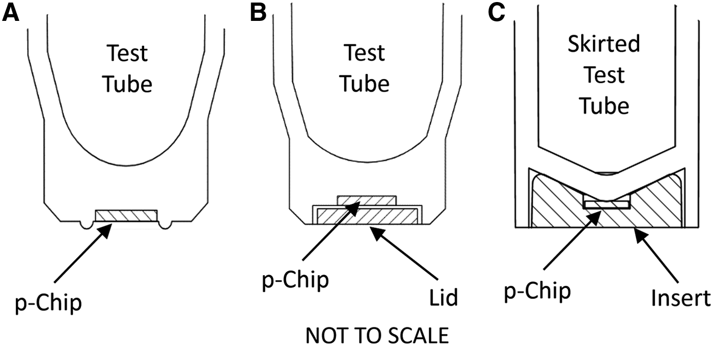
Principles of three tested approaches to tagging sample test tubes with p-Chips.
Custom test tube design with a cavity for a p-Chip and a protective plastic disc
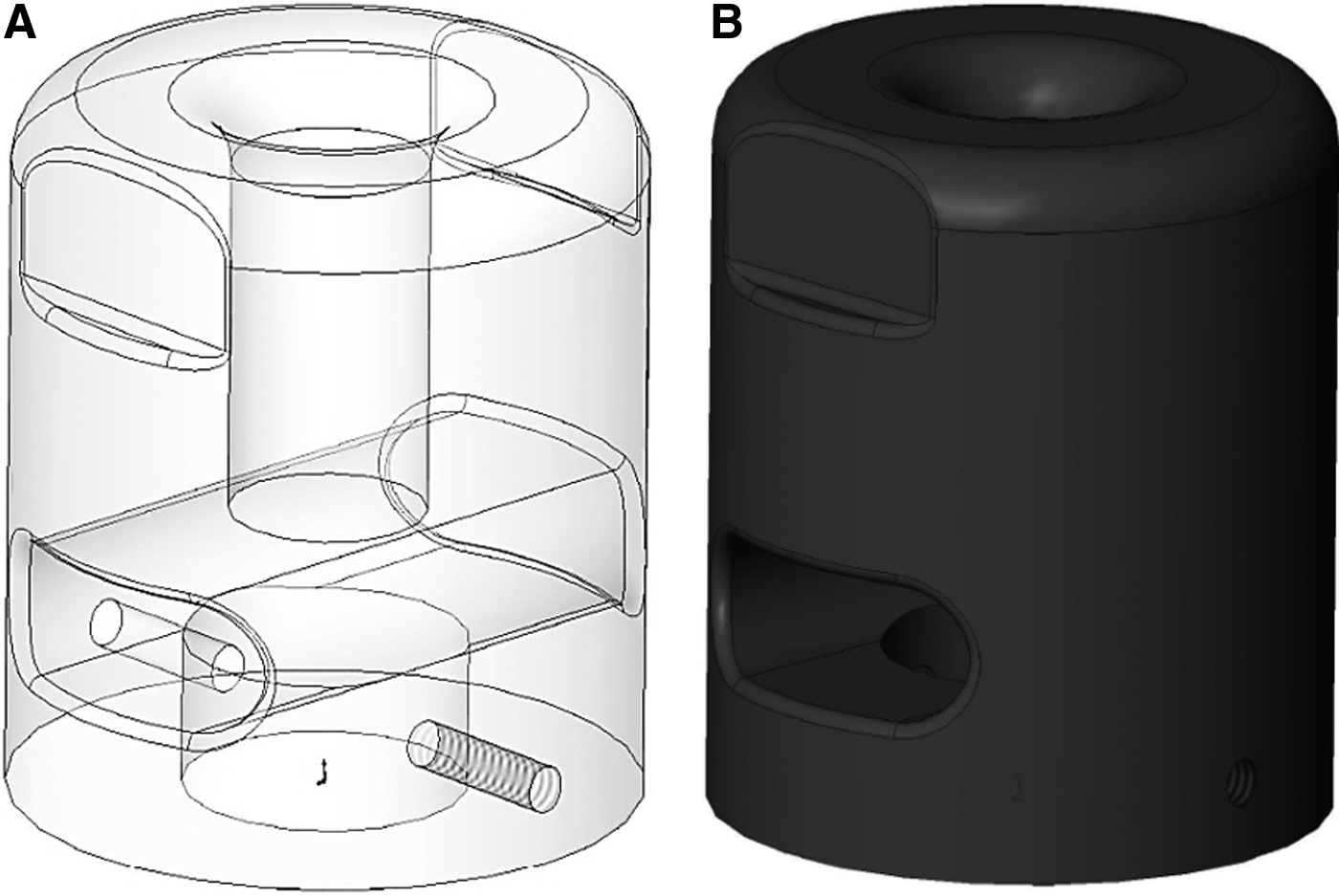
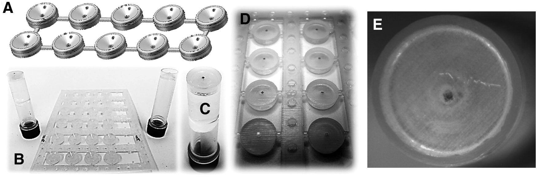
Common 1.4 mL format polypropylene test tubes were custom-molded (Isthmus Scientific) to have a recess in their bases to accept a p-Chip. This recess is designed within the base of the tube such that it may be covered by a separate polypropylene disc. Next, a group of test tubes are combined into an array that facilitates semiautomatic processing. The test tubes are aligned so that the open recesses are available for filling. p-Chips oriented with the circuit side up are placed in the recesses. Polypropylene discs of the same diameter as the rims of the recessed portions of the test tube bases are gently inserted into the recesses in preparation for the heat staking that follows. The array is covered with a Teflon cloth, and a thermal block heated to a surface-wide uniform 175°C is pressed down upon the test tubes for several seconds, melting the polypropylene discs into the surrounding base material, fusing the two pieces. The heat source and Teflon sheet are then removed and the array cooled. The design is illustrated in Figure 7, and its implementation is shown in Supplementary Figure S3.
A custom design of test tube for molding in preparation for tagging with a p-Chip. To assemble the test tube, the p-Chip is placed into a pre-molded square indent in the bottom of the test tube, then a cover is placed over the p-Chip and heat-staked in an assembly fixture (not shown).
Thermal embedding of p-Chips in center bottom of test tubes
Using a specially designed metal fixture onto which a p-Chip has been placed, the chip is heated to a temperature above the melting point of the plastic. For polypropylene, the melting temperature is around 162°C. The heated p-Chip is then pressed into the plastic in the center bottom of the test tube. The fixture has a dual function: first, it heats the p-Chip to a temperature higher than the plastic's melting point; and second, it holds the p-Chip in place by applying a vacuum. The vacuum is released after the p-Chip is embedded into the test tube.
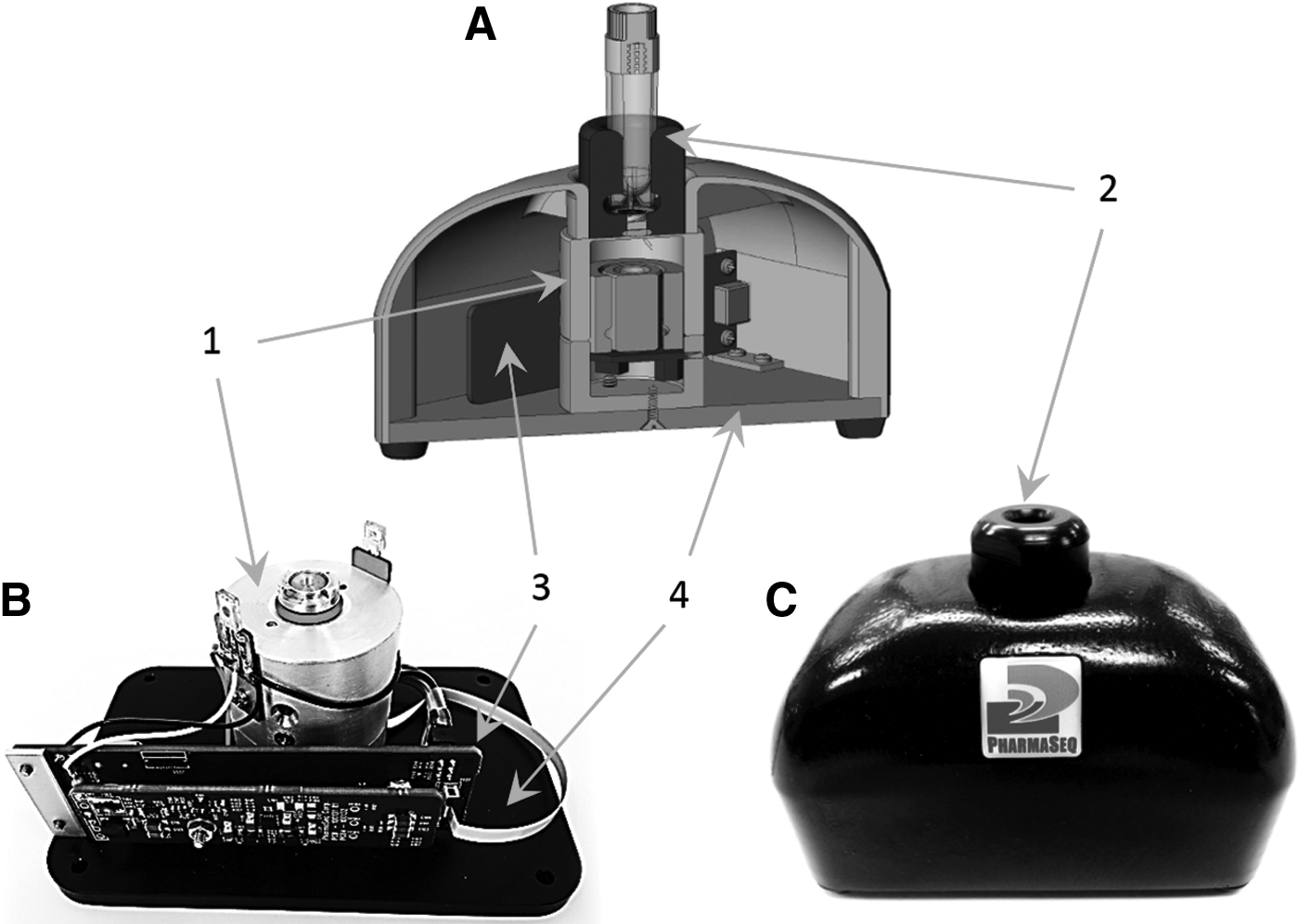
The design and a picture of the fixture are shown in Figure 8. The main component is a soldering iron tip with the vacuum channel passing through it. The chip-picking tip with a temperature higher than 162°C is one end of a bent stainless steel tube that has a 0.02″ outside diameter and a 0.01″ inside diameter. This passes through a 21-gauge stainless steel tube that has a 0.03″ outside diameter and a 0.024″ inside diameter. The other end of the bent tube connects with a 21-gauge stainless steel tube that connects a Teflon tube to a 15 psi vacuum on the hot tip end.
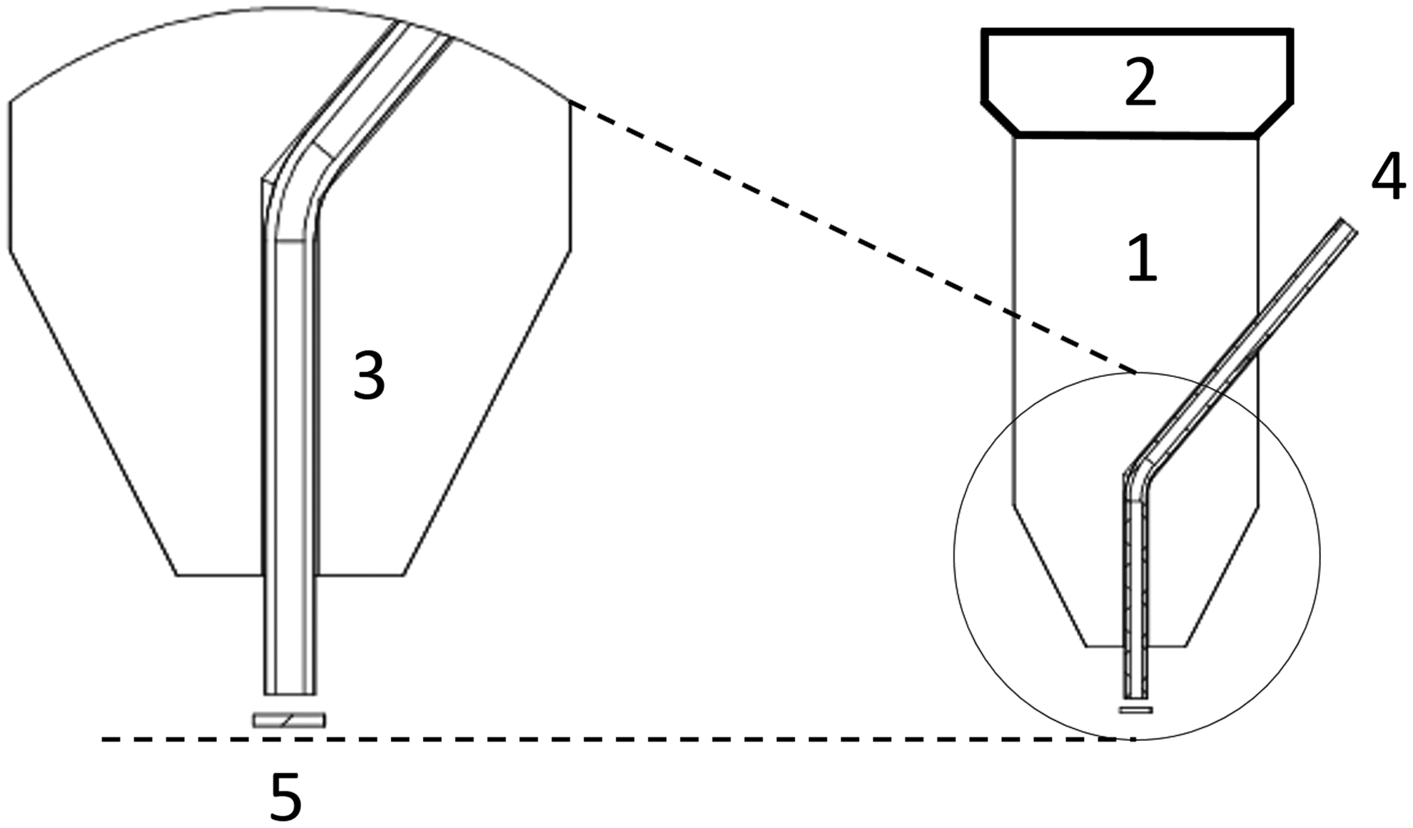
Fixture for thermal embedding of p-Chips in plastic test tubes. (1) metal chuck that is placed in robot; (2) heating element; (3) channel in the chuck with an inserted metal tube for supplying vacuum for handling of the p-Chip; (4) source of vacuum; (5) p-Chip.
Tagging can be done manually by taking a spring-loaded hand press, similar to one normally used for a benchtop drill press, and fitting it with a soldering iron that has been modified with a tip that incorporates a hollow tip to which a vacuum may be applied. Preferably, tagging can be performed by the pick-and-place robot, described in the Pick-and-Place Robot for Tagging Sample Test Tubes with p-Chips section. A large number of test tubes (>30,000) have been robotically tagged using this approach. Examples of such test tubes are shown in Figure 9.
Thermal tagging of test tubes with p-Chips.
p-Chip-carrying plastic insert for skirted vials
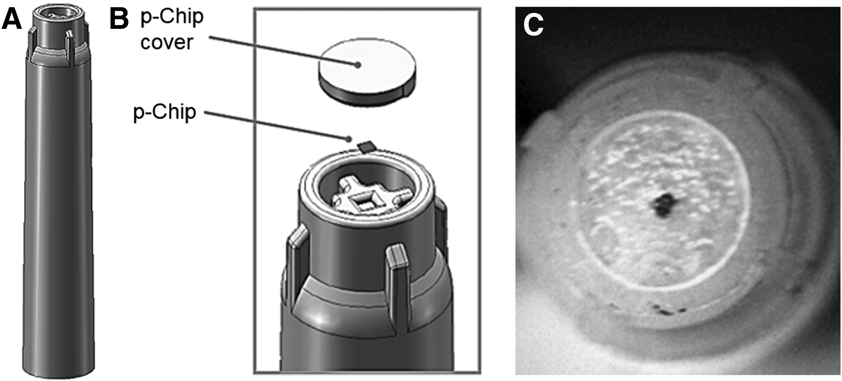
Certain types of skirted vials, for example, a VWR's 2 mL 89004-302 polypropylene vial, have a continuous and sturdy skirt into which a plastic disc carrying a p-Chip can be stably inserted. A suitable disc was designed and 3D printed (Fig. 10). Five variations of a design were fabricated, differing in outer diameter, height, and curvature of the inset. These five designs were arrayed and 3D-printed with the Digital ABS Polyjet Photopolymer using a Precision 3D printer from Stratasys (Eden Prairie, MN). Upon receipt of the arrayed discs, p-Chips were affixed using an epoxy glue and press-fitted into the bottom of the VWR vials. The inserts performed well in testing and no large differences were observed for the different types. All discs survive temperature cycling between RT and −80°C. Some inserts had a small vent hole built-in to relieve the pressure build-up as a result of inserting the disc.
Test tube tagging retrofitting using 3D printed hard inserts.
Robot for retrofitting test tubes at low temperature
A key requirement of the biorepository community is the need to rapidly retrofit frozen legacy samples with tags such as p-Chips while minimizing rises in temperature. The fastest and most durable method of embedding p-Chips in plastic test tubes is through the use of a process that very rapidly melts the chip into the base of a test tube carrying a frozen sample.
The objective here is to tag a test tube containing a biological sample while keeping it at low temperature (typically −80°C, or lower). The requirement is that the temperature of the sample cannot increase by more than 10°C at any time during the entire handling and retro tagging process. The principle of the method is similar to thermal tagging with two key differences: (1) the test tube is kept at −80°C (usually on a dry ice/ethanol bath) at all times except when it is withdrawn and moved for tagging (typically the whole operation takes less than 10 seconds); and (2) the p-Chips reside on a flat metal hot plate that is heated to above the plastic's melting temperature. The test tube, moved by a robot, touches the p-Chip and the plate very briefly (2 seconds or less) and is then returned to the low temperature bath.
A Tecan Cavro Omni Mini three-axis gantry type mini-robot, which is commonly used in fluidic handling applications, was used for retro thermotagging. It was augmented by a number of custom attachments that include a test tube holder chuck, a test tube aligner, an aligner support, a robot structural mounting assembly, a hot plate mount, a thermal shield, an alignment fixture for the p-Chip plate, a nonstick polyceramic p-Chip plate, and a raised post polyceramic-coated p-Chip plate. A system overview is shown in Figure 11. Detailed features are shown in Supplementary Figs. S4 and S5.
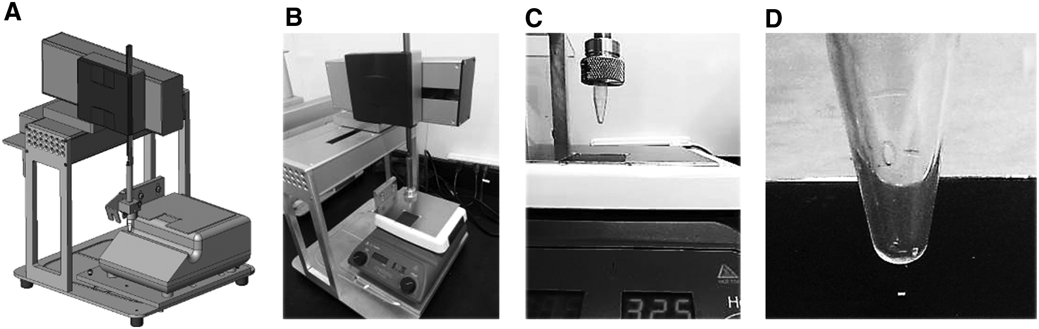
Retrofit vial tagging, semi-automatic thermal method.
Each element was developed in response to observations noted during development and testing. For example, thermal emissions from the hot plate raised the temperature throughout the work area to excessive levels. Robot parts are rated for 150°C maximum exposure. A heat shield was added to the hot plate tag area to limit radiative heating in areas most susceptible to damage. Proper design of the “landing zone” for the thermal p-Chip tagging process places it in an area that maintains a near-constant temperature yet is accessible by the robot. The purpose of the robot was to provide the precise, repeatable positioning needed to reproducibly place a test tube tip onto the heated surface (temperature between 170°C and 250°C depending on the melting temperature of test tubes) without human intervention.
Test tube retrofitting method
This method was used to retrofit already frozen test tubes placed in a dry ice/ethanol bath (−78°C). A set of target p-Chips were prepared using a custom built picker/placer robot designed by PharmaSeq (Supplementary Fig. S2). An array of 7 × 7 p-Chips was placed robotically, circuit side down, on an aluminum plate that bears a high temperature-resistant, polyceramic nonstick material. At room temperature the plate was coated with a 5% carboxymethylcellulose solution to provide a tacky surface on which to secure the p-Chips during and immediately following placement to ensure they remain in place throughout the procedure. The adhesive—essentially a paper-thin veneer once dry—evaporates on exposure to the temperatures used in the tagging process, freeing the heated p-Chips to transfer from the plate as they melt into the plastic test tubes being pressed down upon them.
The robot setup comprised the above described tagging station using the Tecan Cavro robot. To determine the temperature, Type K thermocouples formed of 0.01″ thick wire leads were inserted into the test tubes that were filled with phosphate-buffered saline and frozen to −80°C. Before use, these test tubes were moved into the dry ice/ethanol bath. The hot plate was preheated and the thermocouples were plugged into a Data Acquisition Module (Omega USB TC08) so that temperature values could be collected in real time. After initialization of the robot's controller, the operator rapidly removed each test tube from the bath and affixed it to the holder chuck. He then activated the runtime sequence in the control software—all as quickly as possible, to limit the time during which the test tubes would be exposed to ambient temperature and therefore limiting the thermal rise in the samples. The robot rapidly moved to an area where the test tube was aligned to true vertical; then, the robot positioned the test tube at the target touchdown point, as predetermined from a coordinate data generated when the p-Chips were originally placed by the robot. The test tube was pressed down onto the target p-Chip, lifted away to the retrieval position, and returned to dry ice/ethanol bath by the operator.
Testing (Fig. 12) of the retrofitting method was performed on a simulated sample, 0.5 mL of water, in a test tube equipped with a thermocouple the end of which was placed near (within 0.5 mm) the bottom of the test tube. The sample temperature at the beginning of the experiment was −77°C (dry ice/ethanol bath). The measurements showed that the low temperature of the sample in the test tube was reasonably maintained throughout the tagging process. That is, the temperature of the sample did not increase by more than 10°C. Most of the increase (7°C) was caused by a short, ∼10 seconds, exposure of the test tube to room temperature. The temperature increase caused by either the p-Chip or the hot plate was ∼3°C. These results show that the method allows maintaining sample temperature and preserving sample integrity during retro fitting test tubes with p-Chips.
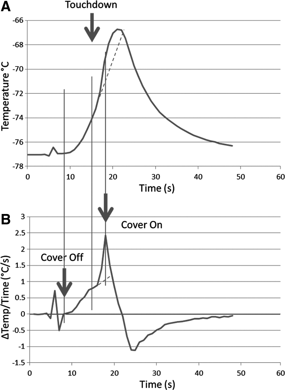
Testing of sample temperature during the retrofit tagging process.
Properties and performance of the tagging system
The PharmaSeq system has been developed primarily for −80°C or higher temperature storage, but operation at lower temperatures is also possible due to the stability of the p-Chips down to temperatures associated with liquid nitrogen. Our experiments demonstrate that performance at −80°C is flawless. In addition, the readout capability through frost is outstanding when compared to handwritten or optical barcoded labels.
We have performed extensive testing on p-Chips and p-Chip-tagged test tubes under various conditions typically encountered in biorepositories. The results, summarized below, support suitability of p-Chips as tags for use in biorepository and related operations where rapid, high-quality reading is essential.
Long-term low temperature stability of p-Chip arrays
Polypropylene arrays, each containing 100 p-Chips (Supplementary Fig. S1), were stored at −80°C and −196°C. A single array was removed from each temperature condition at 30, 90, 182, and 364 days, and IDs were read with the PharmaSeq wand, as described in the Materials and Methods section. No p-Chip failures were observed. One hundred of 100 chips embedded in each array were read successfully after being removed from long-term storage at all temperatures and time points.
Low temperature cycling stability of p-Chip arrays
A single p-Chip array containing 100 chips (Supplementary Fig. S1) was placed in liquid nitrogen after its temperature was reduced to −90°C in a controlled rate freezer. After 24 hours, the array was removed from liquid nitrogen and allowed 6 hours to reach room temperature. One hundred of 100 p-Chips were read successfully and the liquid nitrogen treatment was repeated on the same array a second time. Again, 100 of 100 p-Chips produced successful reads of IDs.
An additional p-Chip array containing 100 chips was placed into a −80°C freezer. Each p-Chip read successfully after the grid was returned to room temperature. This cycling was repeated a total of 15 times over 3 weeks, with 100 of 100 p-Chip IDs being read each time.
p-Chip chamber integrity testing of tagged cryovials
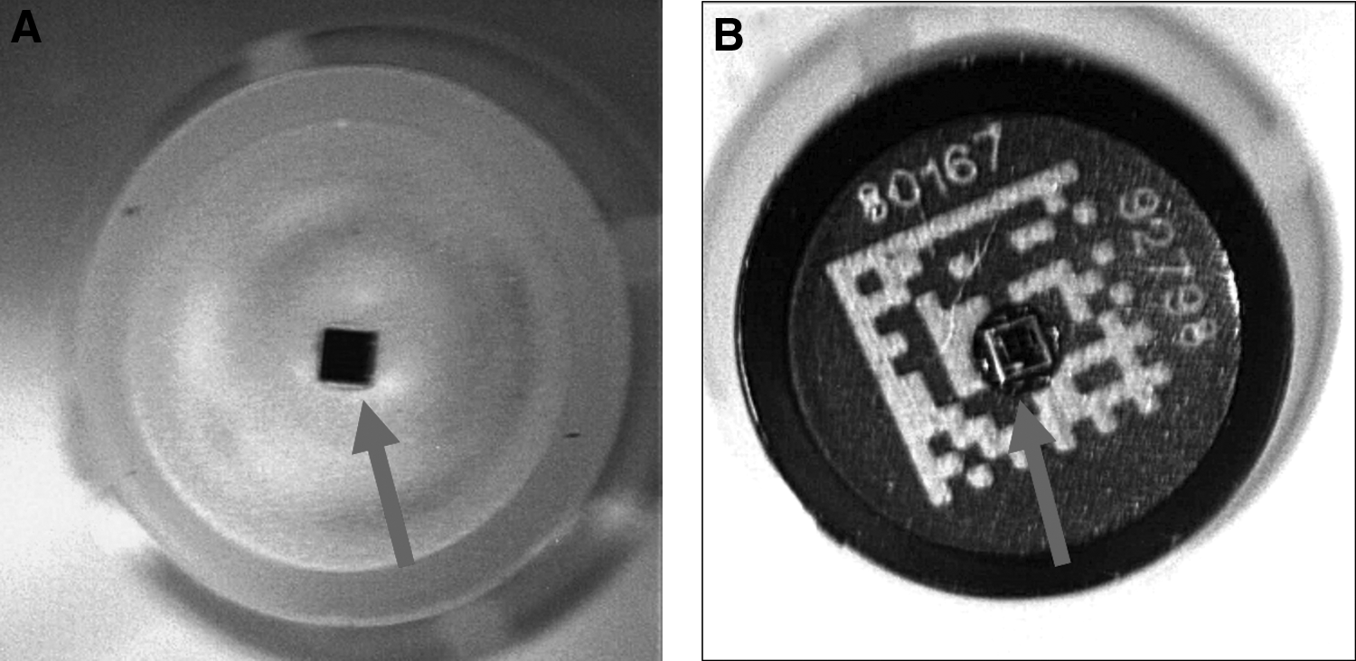
Testing of the structural integrity of p-Chip tagged cryovials (Isthmus Scientific; Fig. 10) was performed to assess the presence of cracks, fissures, or channels leading into the recessed p-Chip chamber. Ten test tubes were immersed in a Cy3 dye solution and showed no traces of dye when examined by fluorescence microscopy. As a control, holes were manually bored into three additional cryovials and exposed to the same regimen. Dye was readily visible in each channel. It was concluded that no significant fissures exist within the walls of the p-Chip tagged vials and that tube rupture due to expansion of trapped liquid nitrogen is not an issue.
Low temperature cycling stability of p-Chip-tagged cryovials
One hundred p-Chip-tagged cryovials (Isthmus Scientific; Fig. 10) were immersed directly into liquid nitrogen and removed after 1.5 hours. The p-Chips were read with an STR after coming to room temperature and the vials were placed back into liquid nitrogen. This cycle was repeated a total of 10 times. One hundred of 100 p-Chips IDs were read after each cycle. The tubes were replaced in liquid nitrogen for an additional 9 months, after which all 100 p-Chips were successfully read with the STR.
Readout of IDs of p-Chip-tagged vials at ultra-low temperatures
Twenty custom molded cryovials (Isthmus Scientific) with embedded p-Chips were partially submerged in liquid nitrogen, keeping the chip temperature at −196°C during the reading process. All 20 p-Chips IDs were properly read with a room temperature PharmaSeq wand.
Through-frost readout capability of p-Chips in comparison to 2D barcode
Twenty-five p-Chip tagged vials were labeled with a 1D barcoded cryogenic tag (GA International). The 25 dual-tagged vials, along with twenty-five 0.75 mL 2D data-matrix coded vials (Micronic), were stored at −80°C and exposed to frost, as described in the Materials and Methods section (see also Fig. 13). After being removed from the freezer, the ID of each p-Chip was read with the PharmaSeq wand. Vials were removed from the freezer individually to prevent melting of frost before ID reading. Twenty-five of 25 p-Chips read successfully through the acquired frost. The 1D and 2D barcodes were read with a standard commercially available scanner (Microscan HS-21). No 2D data-matrix vials (0/25) and only three 1D barcoded vials (3/25) could be read through the layer of frost. This demonstrates that p-Chipped vials can be read reliably in the presence of frost and have a clear advantage over both 1D and 2D-style labels that are commonly used in biorepositories.
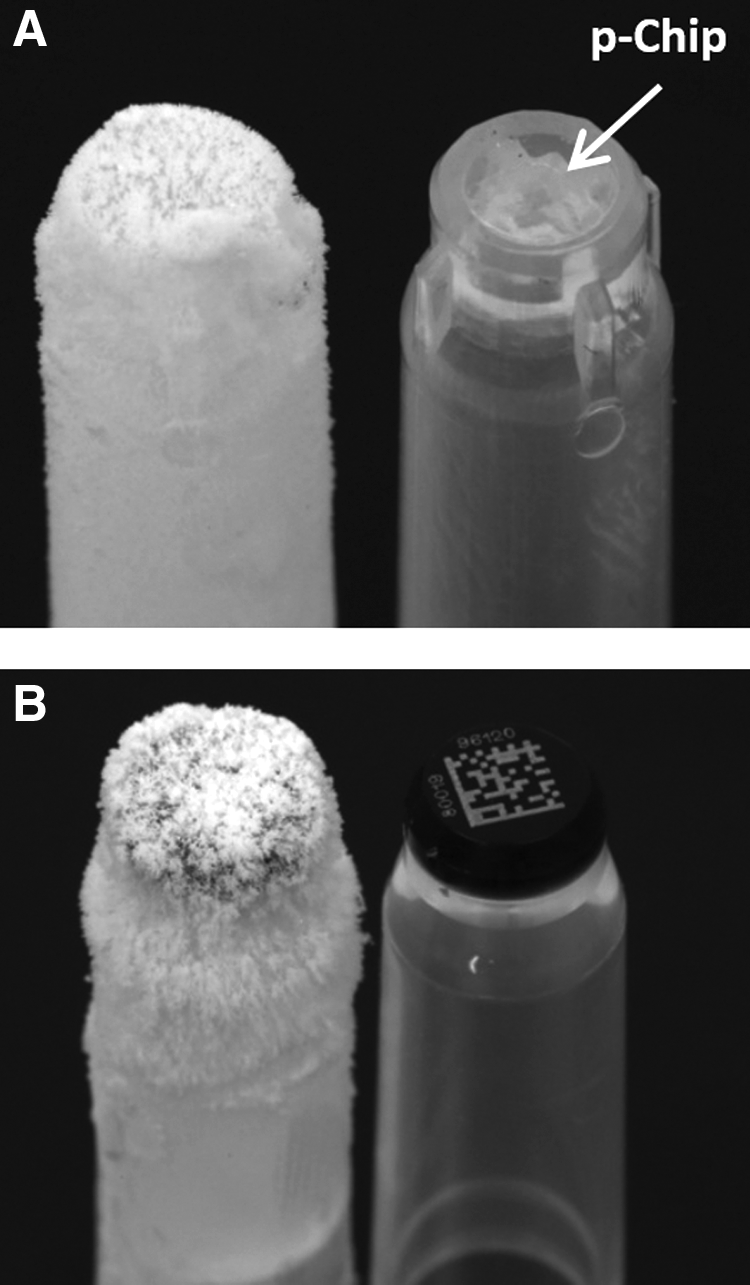
Low temperature testing of p-Chip-tagged test tubes. A comparison of p-Chipped
Change of sample temperature during readout at room temperature
A 1.5 mL Eppendorf vial containing 0.5 mL of phosphate-buffered saline was furnished with a type K thermocouple probe that was inserted and held in place with a disc-shaped piece of plastic. This vial was held in place above a wand on the bench at RT by one of the lab grippers. The temperature in the vial was allowed to reach equilibrium and then measured. The wand was switched on and temperature was monitored. We observed that the temperature observed after 60 seconds of reading was indistinguishable from RT (i.e., was within ±0.1°C of RT), far less than the generally accepted maximum temperature increase allowed. 17 Specifications for natural temperature fluctuation inside a −80°C freezer are much larger, ±1.5°C to 5°C, depending on the make and model. This means that sample heating due to laser light is negligible.
Additional experiments
In additional experiments, we found that p-Chips (sample size = 100) are not affected by the following:
(a) Centrifugation (15 min in a microcentrifuge at about 15,000 g); (b) Exposure to strong near-field microwave radiation (1 hour exposure, standard 700 W microwave oven); (c) Autoclaving dry or in water (a total of 750 repeats of the complete autoclave cycle [20 minutes 120°C] were tested), which is of significance as the p-Chip-tagged test tubes will be able to be used in many common laboratory procedures; or (d) Direct incubation of unembedded p-Chips in solvents (for 15 days), such as dimethylformamide (DMF), dimethyl sulfoxide (DMSO), methanol, ethanol, H2O, pyridine, dichloromethane (DCM), chloroform, acetonitrile, and toluene; 80%–100% of the chips maintained their RF performance.
Discussion
The p-Chip tagging system includes test tubes with p-Chips embedded (by several possible means) into their polypropylene bases, thus assuring absolute connectivity of the tag with the container. Two types of dedicated test tube readers (single and array) capable of determining the ID of the embedded p-Chip and software for operating the reader are also available. The preferred location for the p-Chip is the center of the bottom of the test tube (i.e., along the axis of symmetry), which facilitates rapid readout due to the minimal manipulation required to position the test tube over the reader and a natural tendency to position it in an upward orientation. Once tagged, samples can be read repeatedly and rapidly at a work station either individually or in racks. Sample IDs can then be relayed and associated with an institution's sample database via appropriate software. p-Chip Reader software can integrate with a biorepository's existing database by automatically inserting read IDs into an appropriate field as part of the standard workflow.
There are many advantages to using p-Chipped test tubes. The ability to read through frost is excellent. The p-Chip is stable over a broad temperature range (−196°C to 200°C) allowing highly varied use. It is stable above the melting temperature of polypropylene, facilitating its embedding into test tubes. No two p-Chips have the same ID, which are coded during wafer production. This means that there is virtually no possibility of samples from different sources conflicting with each other or becoming mixed up once they are checked into a biorepository. The current PharmaSeq system is the first instance (to the best of our knowledge) of an electronic tag being permanently embedded in the wall of a small test tube. Placing a traditional RFID tag inside the base material in most, if not all cases, is too costly or logistically impossible owing to their large sizes. Embedding of the p-Chip has significant implications with respect to a system's performance, as it makes the p-Chip resistant to destruction or degradation by handling or by exposure to corrosive chemicals. The p-Chip or a p-Chip-tagged test tube can be subjected to many (>750) autoclaving cycles.
Test tube shape is not a limitation to electronic coding. Because ultra-small p-Chips are placed into the base of a test tube, and the base may have essentially any shape, there is no longer a requirement for a flat surface (typically on the bottom of a test tube) to print a 2D barcode. However, 2D barcodes can be retained on the bottom of tubes in addition to the p-Chip if two independent IDs are desired as shown in Figure 9. This is subject, of course, to the tube design—a flat bottom is typically needed to incorporate a 2D barcode.
According to an NCI Office of Biorepositories and Biospecimen Research (OBBR) report, 18 81% of investigators criticized the poor quality of samples in biorepositories, limiting the scope of their work. NCI's Best Practices for Biospecimen Resources (B.1.4.2) 19 states, “Unnecessary thawing and refreezing of frozen biospecimens or frozen samples of biomolecules extracted from biospecimens are to be avoided…” and, from the same document (B1.5.1), “Samples are retrieved from storage according to biospecimen resource standard operating procedures (SOPs) that safeguard sample quality.” These directives are echoed in the ISBER 2008 Best Practices for Repositories (J9.200 and J10.000) 20 and in NCI's OBBR initiative 21 and general guidelines. 22 Unfortunately, most of the handling procedures used to retrieve and identify a sample often expose the sample and its neighbors to unnecessary thawing. Therefore, an identification technology that functions at low temperatures and is independent of frost buildup obscuring a visible label would meet the requirements of the Best Practices recommendations. The p-Chip tagging system enables physical audits of collections with minimal or no detrimental effects on the quality of the samples. The use of p-Chips may extend the useful lifetime of the specimens, especially those samples subjected to high levels of transactions, which are those most relevant in clinical research. The technology may be employed for retrieval as well as receipt of transported samples.
A significant fraction of test tubes of different types stored in biorepositories do not have automatically readable IDs, thus presenting a challenge to sample retrieval and to maintaining high accuracy of sample identification. In this article, we described a method for retrofitting legacy test tubes with p-Chips. The method does not compromise the low storage temperature and is applicable to many (if not all) types of plastic test tubes.
Further, the method of powering each chip by a highly focused laser beam allows specificity of physical addressing—that is, addressing a dense array of tags in close proximity, one tag at a time, an approach that is not feasible with conventional RFID tags. Using traditional RFID methods, multiple tags in close proximity will respond simultaneously to the interrogating transmitter, resulting in illegible bits and thus preventing reading of the tags. This phenomenon is known as “RFID tag collision.”
Attempts to use RFID tags for tagging biological carries, though mostly in histopathology setting, have been described.23,24 Many difficulties persist. There are advantages of providing power to a tag by light versus RF. Conventional, passive RFID tags harvest power from the driving RF signal using antenna coils that are typically many centimeters in diameter. This results in up to ∼1% efficiency of power transfer to the RFID device, corresponding to a 20 dB path loss typically encountered at close range. In the case of those RFID methods that do not use such a large external antenna, the antenna efficiency drops by orders of magnitude owing to its small size, severely curtailing range and efficacy. Light energy harvested by photodiodes in the PharmaSeq p-Chips results in up to 10% efficiency in power transfer. Thus, because light-powered p-Chips use energy more efficiently, they can achieve greater transmission ranges for the given small antenna size when compared to pure RFID-based approaches.
p-Chip features enable a high level of data security. While some RFID technologies enable additional information content, p-Chips contain only an ID number. All other information related to the sample is stored in a secure database. Thus, nothing about the sample can be determined from the physical sample container itself. In addition, the benefits of the small form factor of the p-Chip antenna limits transmission range to less than 1 cm. Unintended transmissions are not likely.
One concern that could be raised pertains to heating up of the sample when the ID is read. However, the amount of energy delivered by light when the p-Chip ID is being read was shown to be negligibly small in preliminary experiments done at PharmaSeq. Continuous reading of a p-Chip embedded in a cryotube for 1 minute (3,830 reads, a much longer time than is needed to read the ID, by a factor of 1,000) raises the temperature of the sample by only 0.1°C. This is far less than the generally accepted maximum temperature increase allowed, ranging from 10°C to 20°C for the −20°C and −80°C storage, and −150°C storage, respectively. 17 This means that sample heating due to laser light are not be significant under laboratory conditions. Much more significant heat transfer effects are likely to be due to the presence of the sample inside of, or near, a reading device warmed up by internal electrical circuits. An effort will be undertaken to reduce the time a test tube spends inside or near the ID reader or, as indicated earlier, a forced or passive cooling device may be added.
Conclusions
The results obtained to date confirm the feasibility of tagging test tubes with p-Chips and their resilience to extremely low temperatures. Substantial equivalence to barcodes in reading frost- and obstruction-free test tubes has been demonstrated. What is critically important is the demonstration of superior ID reading by the PharmaSeq system of frosted test tubes. This is in sharp contrast to the limited readability of both 1D and 2D barcoded test tubes under identical conditions.
The PharmaSeq tagging system, because of the many attractive properties of the p-Chip itself (ultra-small size, ruggedness, activation by light, and low cost), is in an excellent position to provide a significant alternative to barcoding and RFID tagging in biorepositories. While limitations of barcoding are very well understood, barcoding has not yet been displaced in any significant way since alternatives, such as traditional RFID tagging, etching, and printing, while eliminating certain shortcomings, introduce issues of their own. In addition, a method was presented (retrofitting) for tagging legacy samples stored in plastic tubes at low temperature without significantly raising sample temperature. There is clear potential for adoption of the p-Chip tagging system as the new standard for tagging many types of specimens for processing and storage under demanding conditions.
Footnotes
Acknowledgments
We thank Dr. Richard G. Morris for reviewing and editing the article and for his thoughtful comments. We thank Dr. David Toke and Dr. Mark Cosentino for many suggestions related to this project. The work was supported by a grant from the National Institutes of Health (CA163008 to W.M.).
Author Disclosure Statement
Several authors (W.M., W.M.K., J.Q., K.G., M.G., and E.F.R.) own equity in PharmaSeq, Inc. W.M., M.G., J.Q., and E.F.R. are the inventors on a pending U.S. Patent Application Number US 13/239,779 titled “Tagging of Small Containers for Biological and Chemical Samples with Light-Activated Microtransponders.” J.Q. and W.M. are the inventors on a pending U.S. Patent Application Number US 62/286,001 titled “Microchip Affixing Probe and Method of Use.”
References
Supplementary Material
Please find the following supplemental material available below.
For Open Access articles published under a Creative Commons License, all supplemental material carries the same license as the article it is associated with.
For non-Open Access articles published, all supplemental material carries a non-exclusive license, and permission requests for re-use of supplemental material or any part of supplemental material shall be sent directly to the copyright owner as specified in the copyright notice associated with the article.