Accurate Quantification of the Optical Absorption Coefficient and of the Thermal Relaxation Time for PMMA and for Low-Water-Content Media During Early Ablation with CO 2 Laser Beam at the Wavelength of 10.6 μm
Available accessResearch articleFirst published online January, 2011
Accurate Quantification of the Optical Absorption Coefficient and of the Thermal Relaxation Time for PMMA and for Low-Water-Content Media During Early Ablation with CO 2 Laser Beam at the Wavelength of 10.6 μm
Objective: This article describes a new mathematical approach for a more accurate identification of the optical absorption α (per centimeter) and the thermal relaxation time τr (seconds) of dry poly(methyl-methacrylate; PMMA) at λ = 10.6 μm. Background: The data available in the literature do not accurately describe the numeric value of α (per centimeter) for PMMA and other biologic media. The relaxation time, the surface threshold time, and the heat incubation time are all reported on Literature in rather inaccurate fashion. Methods: Several well-polished PMMA blocks (1 × 4 × 4 cm) were perpendicularly exposed to focused CW radiation of CO2 medical laser devices showing a TEM22 mode. The exposure was kept constant at 10-W CW. A theoretic focal length of 0.5 inches has been extrapolated to better study the most relevant threshold conditions for ablation on PMMA. Results: Values of α = 536.9 per centimeter and τr = 818 μsec for the PMMA at 10.6 μm were identified. With a similar approach, the same parameters were determined for low-water-content tissues, along with other key thermodynamic coefficients, such as the energy threshold of ablation. The starting radial speed of ablation of the “horizon” of the crater was found to be equal to 0.57 cm/sec, with a threshold average power density for ablation equal to 11.5 W/cm in CW mode. The computerized diagnostic CT2 tool proposed by the same author has been also extended to include these preliminary results.
Introduction
The application of CO2 laser beams in the treatment with biomedical media has been attempted by both industrial and research laboratories for more than 25 years. In the past, many studies1–3 have been published on both mechanical and thermodynamic measurements and models for laser-beam spreading in biologic tissues and also in media that simulate the characteristics of a given biologic substance exposed to laser radiation. Poly(methyl methacrylate) (PMMA) is a polymer with several applications in medicine and biology: its thermal properties and characteristics are very similar to those of human and animal compact tissues, such as compact bones and dentin.4,5
Several mathematical aspects of this analysis were published in the past by Canestri, both isolating the LCA model6,7 and numerically solving the Canestri-Langerholc equation.8 Currently, the data available in the literature do not allow identify the numeric value of α per centimeter with satisfactory accuracy. Thanks to this two-step procedure, several clinical applications can be better analyzed, planned, and conducted with higher precision.
Materials and Methods
The approach described here consists of two steps. Because of the low absorption of the λ = 10.6 μm radiation in media with low water content, PMMA is ideal to visualize crater shapes and relative changes, depending on the variation of the key laser device's output parameters. In the first step, several PMMA blocks (1 × 4 × 4 cm) were exposed to 10-W CW radiation of a commercially available CO2 medical laser device (property of the Sackler School of Medicine, Department of Health Physics, Tel Aviv University, Tel Aviv, Israel) showing a TEM22 mode. Each block was exposed to the beam on a horizontal and polished surface of each sample. A set of four focal lengths [0.5, 5, 7.5, and 15.75 inches (400 mm)] were exposed to 10-W output power. This required first initial experimental step allows us to collect the numeric data needed for the second logical step, which consists of the mathematical extrapolation of both the behavior of the focal length of 0.5 inches and the minimal output power in watts (Wm) to obtain early ablation in PMMA at λ = 10.6 μm. The combined threshold conditions present during early ablation are of paramount importance in the accurate determination of the optical absorption, the relaxation time, the volumetric threshold time, and the heat-incubation time of biologic media, all described in the literature in more qualitative than quantitative fashion.
Discussion
Beer's Law regulates the absorption modalities of an incident light-wave beam into a given medium:\documentclass{aastex}\usepackage{amsbsy}\usepackage{amsfonts}\usepackage{amssymb}\usepackage{bm}\usepackage{mathrsfs}\usepackage{pifont}\usepackage{stmaryrd}\usepackage{textcomp}\usepackage{portland, xspace}\usepackage{amsmath, amsxtra}\pagestyle{empty}\DeclareMathSizes{10}{9}{7}{6}\begin{document} \begin{align*} I ( z ) = I_0 \cdot \exp ( - \alpha \cdot z ) \tag{1} \end{align*} \end{document}
where I0 is the incident power on the laser-beam's spot, α is the absorption coefficient of the irradiated medium, and I(z) is the resulting power at the depth Z below the laser-beam's spot on the surface. The beam-profile shape, described in the literature by the m2 factor,9 defined as M2 = (2n + 1), where n = 0 is valid for gaussian TEM00 laser-beam profiles, is a key beam profile coefficient. For the case described here, M2 = 5 represents the TEM22 beam profile, n = 2.
The first parameter used in this calculation is the relaxation time τR,10 defined as the time threshold below which the thermal damage produced by any given laser beam is minimized:\documentclass{aastex}\usepackage{amsbsy}\usepackage{amsfonts}\usepackage{amssymb}\usepackage{bm}\usepackage{mathrsfs}\usepackage{pifont}\usepackage{stmaryrd}\usepackage{textcomp}\usepackage{portland, xspace}\usepackage{amsmath, amsxtra}\pagestyle{empty}\DeclareMathSizes{10}{9}{7}{6}\begin{document} \begin{align*} \tau_R = \frac{1} {4 \cdot k \cdot \alpha^2 } \tag {2} \end{align*} \end{document}
where α is the absorption coefficient, as in Eq. 1, and k is the thermal diffusivity of the irradiated tissue. In another study,11t0 was identified as the time of the start of the ablation process (surface threshold), which occurs slightly after the start of the irradiation at ton (Fig. 1). Then, from room temperature, the absorbed energy reaches the ablative-condition threshold on the surface of the irradiated media at t0:\documentclass{aastex}\usepackage{amsbsy}\usepackage{amsfonts}\usepackage{amssymb}\usepackage{bm}\usepackage{mathrsfs}\usepackage{pifont}\usepackage{stmaryrd}\usepackage{textcomp}\usepackage{portland, xspace}\usepackage{amsmath, amsxtra}\pagestyle{empty}\DeclareMathSizes{10}{9}{7}{6}\begin{document} \begin{align*} t_0 = 9.10^3 \cdot \frac {1} {\alpha \cdot I_0} \tag {3} \end{align*} \end{document}
where, again, α is the absorption coefficient, as in Eqs. 1 and 2, and I0 is the power density of the beam [watt/spot area (W/cm2)], which is perpendicularly incident on the surface of the irradiated medium. Because of the necessary unit balance of Eq. (3), it is correct to say 9,000 J/cm2. In parallel, the LCA algorithm12 predicts the existence of a “volumetric threshold time” t1b at which the ablated volume can be measured by using standard 3-D geometric formulations. A basic unit volume b of media located under the laser spot increases in temperature up to its threshold and marks the first volume-ablation step at t1b, which is the solution12 of the integral equation:\documentclass{aastex}\usepackage{amsbsy}\usepackage{amsfonts}\usepackage{amssymb}\usepackage{bm}\usepackage{mathrsfs}\usepackage{pifont}\usepackage{stmaryrd}\usepackage{textcomp}\usepackage{portland, xspace}\usepackage{amsmath, amsxtra}\pagestyle{empty}\DeclareMathSizes{10}{9}{7}{6}\begin{document} \begin{align*}(\beta_i - \gamma_i ) + \int \limits_0^{t_{1b}} Z_{bk} ( t ) \ dt = \int \limits_0^{t_{1b}} \ R_{bk} (t) \ dt \tag{4} \end{align*} \end{document}
or, t = t−1 (R), we can also rewrite Eq. (4) as\documentclass{aastex}\usepackage{amsbsy}\usepackage{amsfonts}\usepackage{amssymb}\usepackage{bm}\usepackage{mathrsfs}\usepackage{pifont}\usepackage{stmaryrd}\usepackage{textcomp}\usepackage{portland, xspace}\usepackage{amsmath, amsxtra}\pagestyle{empty}\DeclareMathSizes{10}{9}{7}{6}\begin{document} \begin{align*}(\beta_i - \gamma_i) + \int \limits_{R_{b , spot}}^{R_{1b}} \bigg( \frac {Z_{bk} (t^{-1} (R_{bk}))} { \big| { \vec V } _ { bR \ start } \big|} \bigg) \ dR - \int \limits_0^{t_ {1b}} \ R_ {bk}(t) \ dt = 0 \tag {5} \end{align*} \end{document}
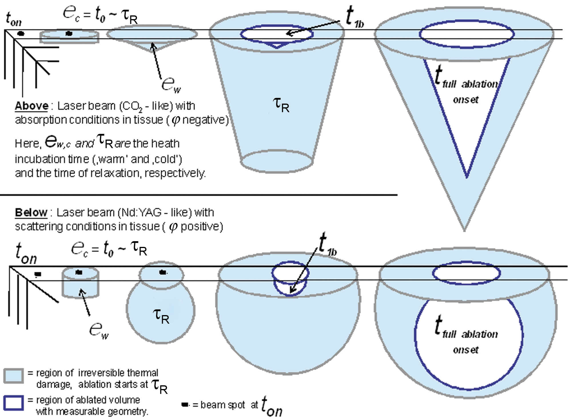
where R(t) and Z(t) are the known radius and the depth of the crater produced in PMMA by a “k” focal lens on a TEM22 CO2 beam profile after an exposure time of t1b and focused on Rb,spot. Here, \documentclass{aastex} \usepackage{amsbsy} \usepackage{amsfonts} \usepackage{amssymb} \usepackage{bm} \usepackage{mathrsfs} \usepackage{pifont} \usepackage{stmaryrd} \usepackage{textcomp} \usepackage{portland, xspace} \usepackage{amsmath, amsxtra} \pagestyle{empty} \DeclareMathSizes {10} {9} {7} {6} \begin{document}$$ \big| {\vec V}_{bR \ start} \big| $$ \end{document} is the surface development speed of the crater border, which will then approach a steady value, even during the irradiation.11 Here, per definition, we can write R1b = R(t1b). The numeric nondimensional parameter φ ≡ (βi − γi), here published with clearer annotation, was described.(12, Appendix) It will be demonstrated in future studies that the absorption effects produce negative φ values, whereas scattering effects produce positive φ values when PMMA is irradiated with different types of lasers, such as CO2, compared with YAG devices. In Fig. 1, a schematic rendering of the evolution of the first four phases of sublimation in relation to φ, ton, t0,t1b, τR, and ɛ is presented for absorption versus scattering conditions (CO2 vs.YAG lasers). The value t1b = 3.5 · 10−4 sec has been calculated,7 and it corresponds to a minimum ablated PMMA unit volume of Vb = 30 · 10−4mm3 ablated by a lens of 0.5 inches12 at 10 W.
Scattering ablative conditions at the beginning of the ablation phase.
The fourth time-dependent coefficient to consider for completeness is ɛ, which is the “heat incubation time” observed in PMMA.13 It relates to a period in which the heat is absorbed by the polymeric structures like those in the PMMA, allowing the ablation process to continue between two consecutive laser pulses.
In this way, we reach a condition of minimal laser damage, which is by definition the relaxation time τR (Eq. 2). For the very first heat-incubation step after the irradiation has started, we can write\documentclass{aastex}\usepackage{amsbsy}\usepackage{amsfonts}\usepackage{amssymb}\usepackage{bm}\usepackage{mathrsfs}\usepackage{pifont}\usepackage{stmaryrd}\usepackage{textcomp}\usepackage{portland, xspace}\usepackage{amsmath, amsxtra}\pagestyle{empty}\DeclareMathSizes{10}{9}{7}{6}\begin{document} \begin{align*} t_{0} - \varepsilon = \tau_R \tag{6} \end{align*} \end{document}
where ɛ is of course very small at the starting point of the ablation,12 but not zero. We cannot use t1b in Eq. (5) because, at t1b itself, a portion of volume already has been ablated, going against the concept of “incubation,” which is strictly associated with the existence of an already irradiated and absorbing, but not yet ablated volume.
Now, observing that both t0 and τr contain the absorption coefficient α, we can write\documentclass{aastex}\usepackage{amsbsy}\usepackage{amsfonts}\usepackage{amssymb}\usepackage{bm}\usepackage{mathrsfs}\usepackage{pifont}\usepackage{stmaryrd}\usepackage{textcomp}\usepackage{portland, xspace}\usepackage{amsmath, amsxtra}\pagestyle{empty}\DeclareMathSizes{10}{9}{7}{6}\begin{document} \begin{align*} \left( 9 \cdot 10^3 \cdot \frac{1}{\alpha \cdot I_0} \right) - \varepsilon = \frac{1}{4 \cdot k \cdot \alpha^2} \tag {7} \end{align*} \end{document}
I demonstrated12 that, providing Io = Fth/t1b and ɛ → 0 in Eq. 7, the following values are true for PMMA and that they are constant and independent of the CO2 laser setup, provided that early ablative conditions are present:\documentclass{aastex}\usepackage{amsbsy}\usepackage{amsfonts}\usepackage{amssymb}\usepackage{bm}\usepackage{mathrsfs}\usepackage{pifont}\usepackage{stmaryrd}\usepackage{textcomp}\usepackage{portland, xspace}\usepackage{amsmath, amsxtra}\pagestyle{empty}\DeclareMathSizes{10}{9}{7}{6}\begin{document} \begin{align*} \textbf{\textit{Fth}} & = 7.17 J / cm^2 \\ \alpha & = 536.9 cm^{-1} \tag{8} \end{align*} \end{document}
One can mathematically demonstrate the correctness of the assumption Io = Fth/t1b for PMMA with ɛ → 0 used in Eq. (7) and not the apparently more intuitive Io = Fth/(t0 + t1b), because one can say that the total exposure time has been (t0 + ɛ + t1b) from the moment of the start of the irradiation at ton in “cold” medium (again for fk → 0 and for ɛ → 0 ).
This demonstration proves that, in case one would consider Io = Fth/(t0 + t1b), then, as a consequence, a key boundary condition would be violated, leading to a wrong conclusion for PMMA.
Per definition from Eq. 3:\documentclass{aastex}\usepackage{amsbsy}\usepackage{amsfonts}\usepackage{amssymb}\usepackage{bm}\usepackage{mathrsfs}\usepackage{pifont}\usepackage{stmaryrd}\usepackage{textcomp}\usepackage{portland, xspace}\usepackage{amsmath, amsxtra}\pagestyle{empty}\DeclareMathSizes{10}{9}{7}{6}\begin{document} \begin{align*} t_0 = 9 \cdot 10^3 \cdot \frac {1}{\alpha \cdot I_0} \end{align*} \end{document}
and therefore, by using Io = Fth/(t0 + t1b) for fk → 0 and ɛ → 0:\documentclass{aastex}\usepackage{amsbsy}\usepackage{amsfonts}\usepackage{amssymb}\usepackage{bm}\usepackage{mathrsfs}\usepackage{pifont}\usepackage{stmaryrd}\usepackage{textcomp}\usepackage{portland, xspace}\usepackage{amsmath, amsxtra}\pagestyle{empty}\DeclareMathSizes{10}{9}{7}{6}\begin{document} \begin{align*} t_0 = 9 \cdot 10^3 \cdot ( ( t_0 + t_{1b} ) / \alpha \cdot F_{th}) \end{align*} \end{document}
because all the parameters contained in the second term of the equation are positive. Therefore, the first term of the equation must also be positive, so for the PMMA, we can write (Eq. 3):\documentclass{aastex}\usepackage{amsbsy}\usepackage{amsfonts}\usepackage{amssymb}\usepackage{bm}\usepackage{mathrsfs}\usepackage{pifont}\usepackage{stmaryrd}\usepackage{textcomp}\usepackage{portland, xspace}\usepackage{amsmath, amsxtra}\pagestyle{empty}\DeclareMathSizes{10}{9}{7}{6}\begin{document} \begin{align*} \alpha F_{th} > 9 \cdot 10^3 \cong ( 3 / 4 ) \pi A_e \rho_{\,\,\,J / cm^3} \tag{9} \end{align*} \end{document}
However, by using the PMMA ablation threshold of Fth = 7.17 J/cm2 (Eq. 11), the last equation would imply α > 1,000 1/cm, which is the absorption coefficient of water and of water-rich tissues at the CO2 laser-beam wavelength and not the α of the PMMA (536) and similar other polymers. As we will see later, this is not true for biologic media irradiated at 10.6 μm. This contradiction is mathematically linked to the definition of Io = Fth/(t0 + t1b), which is now proven to be wrong for PMMA. This makes sense from the physical point of view, because no ablative threshold conditions are found Fth relative to ablation in polymers during t0 but only during t1b.
A second and third equation have also been found to be consistent with the laws that describe the calculated surface vectorial speed \documentclass{aastex} \usepackage{amsbsy} \usepackage{amsfonts} \usepackage{amssymb} \usepackage{bm} \usepackage{mathrsfs} \usepackage{pifont} \usepackage{stmaryrd} \usepackage{textcomp} \usepackage{portland, xspace} \usepackage{amsmath, amsxtra} \pagestyle{empty} \DeclareMathSizes {10} {9} {7} {6} \begin{document}$$ {\vec V}_{bR \ start} $$ \end{document} of the crater “horizon” at early ablation in PMMA. This speed factor has been generated in Eq. 4, leading to Eq. 5, because of the change of the variable of integration: physically, it depends on the thermodynamic parameters already used. If the conditions for ablations are met, (for 10-W CW output power focused by a 0.5-inch lens, which is an experimental limiting condition, then the ablative front in PMMA starts at a speed between:\documentclass{aastex}\usepackage{amsbsy}\usepackage{amsfonts}\usepackage{amssymb}\usepackage{bm}\usepackage{mathrsfs}\usepackage{pifont}\usepackage{stmaryrd}\usepackage{textcomp}\usepackage{portland, xspace}\usepackage{amsmath, amsxtra}\pagestyle{empty}\DeclareMathSizes{10}{9}{7}{6}\begin{document} \begin{align*} \mid {\vec V}_{bR \ start} \mid = ( \rho \ A\textbf{\textit{e}} \ k ) / F\textbf{\textit{th}} = 0.569 \ cm / sec \tag{10} \end{align*} \end{document}
where k is the thermal diffusivity of PMMA = 1.06 × cm2/sec, Ae is the PMMA ablation energy = 3.5 · 103J/g, ρ is the PMMA density = 1.1g/· cm3, Fth = 7.17J/· cm2 from Eq. 10, Tcon is the PMMA thermal conductivity = 0.161 × J/sec cm deg C, and Hs is the PMMA specific heat12) = 1.46J/g deg C. Therefore, because the two speeds are the same, we find that for PMMA, the following is true:\documentclass{aastex}\usepackage{amsbsy}\usepackage{amsfonts}\usepackage{amssymb}\usepackage{bm}\usepackage{mathrsfs}\usepackage{pifont}\usepackage{stmaryrd}\usepackage{textcomp}\usepackage{portland, xspace}\usepackage{amsmath, amsxtra}\pagestyle{empty}\DeclareMathSizes{10}{9}{7}{6}\begin{document} \begin{align*} \rho \ k = ( T\textbf{\textit{con}} / H\textbf{\textit{s}} ) = 0.0011 \ g / cm / sec \tag{12} \end{align*} \end{document}
This equation is derived from the calculation of the minimum threshold of output power Wm in watts needed to ablate a given medium by using a focal length of 0.5 inches at λ = 10.6 μm in continuous mode (CW):\documentclass{aastex}\usepackage{amsbsy}\usepackage{amsfonts}\usepackage{amssymb}\usepackage{bm}\usepackage{mathrsfs}\usepackage{pifont}\usepackage{stmaryrd}\usepackage{textcomp}\usepackage{portland, xspace}\usepackage{amsmath, amsxtra}\pagestyle{empty}\DeclareMathSizes{10}{9}{7}{6}\begin{document} \begin{align*} W_m = ( T\textbf{\textit{con}} \ A\textbf{\textit{e}} / \alpha \ H\textbf{\textit{s}} ) \cong ( \rho \ k \ Ae / \alpha ) = 7.4 \pm 0.2 \ mW \tag{13} \end{align*} \end{document}
by using Eq. 8 and relative numeric values. Below this value in mW in CW, the power density on the spot of a 0.5-inch lens will not generate any ablation on the PMMA surface.
By calculating the spot size generated by a 0.5-inch lens in circular approximation with M2 = 5, the power density is then Iocw = 15.35 W/cm2: this value must be considered as reference only, because the 0.5-inch lens has not be physically tested in this study. It represents only a mathematical extrapolation, including the geometry of the area of the spot, assumed to be circular in a TEM22 beam mode for such a small limiting lens. In future studies, it will be proven how this power density is linked to an acceleration. Interesting, however, to notice how this value would be equal to Fth for 1-sec exposure (Eq. 7) if the spot radius of the 0.5-inch lens for a TEM22 mode would be larger by a factor of \documentclass{aastex} \usepackage{amsbsy} \usepackage{amsfonts} \usepackage{amssymb} \usepackage{bm} \usepackage{mathrsfs} \usepackage{pifont} \usepackage{stmaryrd} \usepackage{textcomp} \usepackage{portland, xspace} \usepackage{amsmath, amsxtra} \pagestyle{empty} \DeclareMathSizes {10} {9} {7} {6} \begin{document}$$ {\sqrt 2} $$ \end{document}, suggesting the possible presence of nonlinear conditions for fk → 0 and for ɛ → 0. As demonstrated before, it is correct to use Io = Fth/t1b = 2 · 104 W/cm2: this has to be considered the power density on the 0.5-inch lens spot for the duration of a single pulse Pw = t1b whereas from above, Iocw = 7.17 − 15.35 W/cm2 (depending on the correct assessment of the limiting spot radius) is the power density for an exposure time of 1 sec in continuous wave (CW) mode. Both conditions are equal, and the choice to adopt one or the other is free, depending on the configuration of the laser device to deliver its own laser pulse width and output power in a flexible way. For correctness, the proper annotation of Io is then Io1b to remind us of the presence of a single pulse t1b.
In summary, then, the two equivalent threshold ablating conditions for PMMA are as follows:
Continuous-wave beam delivery: Iocw = 7.17 − 15.35 W/cm2 (for exposure time up to 1 sec, W = 7.4 mW for 0.5-inch lens, r to ( \documentclass{aastex} \usepackage{amsbsy} \usepackage{amsfonts} \usepackage{amssymb} \usepackage{bm} \usepackage{mathrsfs} \usepackage{pifont} \usepackage{stmaryrd} \usepackage{textcomp} \usepackage{portland, xspace} \usepackage{amsmath, amsxtra} \pagestyle{empty} \DeclareMathSizes {10} {9} {7} {6} \begin{document}$$ \textbf{\textit{r}} {\sqrt 2} $$ \end{document}) spot radius) = 11.26 W/cm2 average power density due to the intrinsic experimental uncertainty on r.13
Pulsed-beam delivery: I01b = Fth/t1b = 2 × W/cm2 (single pulse = t1b and for Fth = 7.17 J/cm2 with 0.5-inch lens).
Equations 10 through 13 are fundamental checks of the overall data integrity of all the thermodynamic parameters found. By using Eq. 2, 3, and 6 and knowing that α = 536.9 per centimeter, we can calculate t0,τr and then ɛ by the difference:\documentclass{aastex}\usepackage{amsbsy}\usepackage{amsfonts}\usepackage{amssymb}\usepackage{bm}\usepackage{mathrsfs}\usepackage{pifont}\usepackage{stmaryrd}\usepackage{textcomp}\usepackage{portland, xspace}\usepackage{amsmath, amsxtra}\pagestyle{empty}\DeclareMathSizes{10}{9}{7}{6}\begin{document} \begin{align*} \varepsilon = \textbf{\textit{t}}_0 - \tau_{\textbf{\textit{R}}} = (8.1827 - 8.1817) \cdot 10^{-4} = 10^{-7} \ \sec \tag{14} \end{align*} \end{document}
As follow-up of the data published in reference 12, I present some additional data about CO2 laser craters produced with silver-halide fibers on rabbit bone and dentin (formalin-treated dry samples) compared with a similar laser device setup without fibers.
Sudden combustion in polymers versus smooth ablation in biologic tissues
From Table 1, it is evident that larger focal produce larger pit size on the surface is combined to lower penetration degree. Doubling the power density together with the pulse width generates more superficial damage (linked to lateral ablation speed) but fewer penetration effects. These are linked primarily to the spot size, to the factor M2 = (2n + 1) = 5, and therefore to the resulting power density. One can see that the presence of water and the anatomic characteristics of the biologic tissue before irradiation play two key roles in the resulting geometry of the crater produced by carbon dioxide lasers. The energy fluence necessary to vaporize low-water-content tissue is approximately Fth = 5 J/cm2 (ablation threshold) versus a value of 7.17 IJ/cm2 calculated for PMMA with very limited water content. In general, CO2 CW energy delivered for <1 msec (Eq. 13) on spot and with a Fth of approximately 5 J/cm2 leads to tissue vaporization measuring <30–40 μm in depth and to an additional extra thermal injury region measuring 50–100 μm. Reports on dentin14 with very short pulses (similar to the pulse length reported in Eq. 13) show a lower value of penetration (1/α) = 1/800 = 0.00125 cm = 12.5 μm versus a PMMA value of (1/536.9) = 18.6 μm, as expected because of the presence of water in the tissue. The same explanation is valid for the thermal relaxation time equal to 818 μsec for PMMA at the CO2 laser wavelength compared with a value ranging from 20 μsec for compact hard tissue up to 600 μsec for soft tissue. In general, all these data can be used as a solution of Eq. 9 demonstrated earlier:\documentclass{aastex}\usepackage{amsbsy}\usepackage{amsfonts}\usepackage{amssymb}\usepackage{bm}\usepackage{mathrsfs}\usepackage{pifont}\usepackage{stmaryrd}\usepackage{textcomp}\usepackage{portland, xspace}\usepackage{amsmath, amsxtra}\pagestyle{empty}\DeclareMathSizes{10}{9}{7}{6}\begin{document} \begin{align*} \alpha \ F_{th} \geq 9 \cdot 10^3 \cong ( 3 / 4 ) \pi A_e \rho_{\,\,\,J / cm^3} \tag{15} \end{align*} \end{document}
Comparison Between PMMA and Low-Water-Content Media (24 h Under Formalin)
Medium
Power density. per pulse (W/cm2)
Energy per pulse (mJ)
Pulse widths (msec)
Freq. (Hz)
Focal lengths (inches)
Crater diameter (mm)
Crater depth (mm)
Bone (compact)
1,500
30
10
1
No fiber fk = 5
0.772
0.257
Bone (compact)
2,300
100
20
4
No fiber fk = 5
0.876
1.100
9
1.017
2.350
Bone (cancellous)
1,600
30
10
3
No fiber fk = 5
0.601
0.389
PMMA (compact)
6,300
30
10
3
No fiber fk = 2.5
0.413
2.083
Dentin (compact)
390
50
20
3
With silver-halide fiber
0.400
0.188
10
1.202
0.703
20
1.330
1.034
Dentin (compact)
6,300
30
10
1
No fiber fk = 2.5
0.313
1.107
It has been demonstrated that this condition is not valid for PMMA; however, it can be used for all biologic tissues irradiated with a CO2 laser beam. As a consequence of that demonstration, the start of the sublimation in biologic tissues takes place during (t0 + t1b), whereas in PMMA, the same takes place only later, during t1b This suggests the presence of sudden combustion effects after energy accumulation and pile-up till the polymeric ignition threshold is suddenly reached, but only at t1b. Before this moment, a nonlinear phase of melting does not produce any crater but rather an irregular thermal injury, leading to the presence of a “shock” burn, which could explain the radius ( \documentclass{aastex} \usepackage{amsbsy} \usepackage{amsfonts} \usepackage{amssymb} \usepackage{bm} \usepackage{mathrsfs} \usepackage{pifont} \usepackage{stmaryrd} \usepackage{textcomp} \usepackage{portland, xspace} \usepackage{amsmath, amsxtra} \pagestyle{empty} \DeclareMathSizes {10} {9} {7} {6} \begin{document}$$ \textbf{\textit{r}} {\sqrt 2} $$ \end{document}) of initial craters in PMMA (Eq. 13). In presence of water, however, the sudden increase of temperature generates immediate water boiling and the carbonization of the tissue, all contributing to the crater formation during (t0 + t1b). All this demonstrates the intrinsic experimental uncertainty on r, which is clearly due to the polymeric chemical structure of the PMMA not present in biologic media. Future investigations will demonstrate that the focal length of 0.5 inches is not the absolute minimal length with surgical relevance: to look for that limit, one must introduce the concept of acceleration of the crater “horizon” at the start of the irradiation. The simple concept of speed in the calculation is not a valid approximation.
New features of the computerized tool CT2
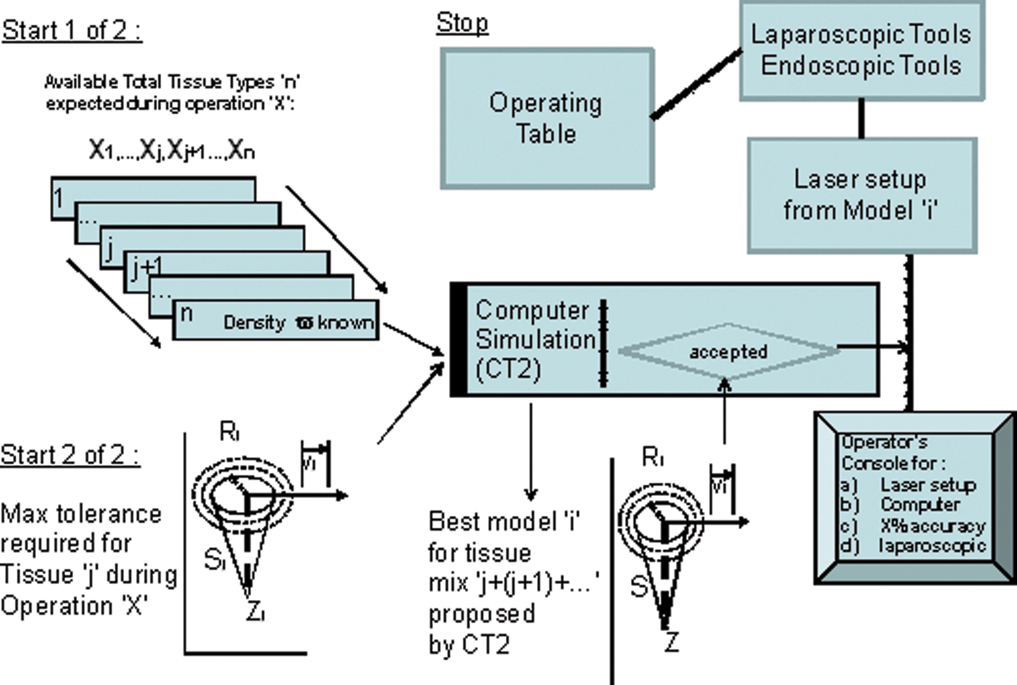
As described,12 and as shown in Table 1 and the results from Eqs. 11 through 14, the computerized tool CT2 can be now extended to other applications, which include the utilization of laparoscopic tools in Minimally Invasive Surgery (MIS). As proposed in Fig. 2, a given surgical operation X will involve n tissues of which the thermodynamic characteristics are known, as in the CT2 protocol proposed elsewhere.12
Description of the main CT2 computer system components for laparoscopic remote control.
The surgeon knows a priori the boundary conditions to be respected to avoid unwanted thermal exposure to healthy tissues; therefore, the computer simulates the surgical operation by using a set of conditions (Eq. 8–12) that respect these boundaries. Once these are validated, the computer controls, both laser-output parameters and the focal length to be used until the end of the surgical intervention. The acquisition interface between the computer and the operating field is managed by a set of multimeters, cameras, network analyzers, and signal analyzers to ensure real-time data transfer from the simulation routine to the operating field and to support the required feedback loops. Further investigations are needed to validate this global procedure completely before adopting it in surgical operations on any living organisms.
Conclusions
The absorption coefficient for PMMA at the wavelength of the CO2 laser beam has been calculated to be α = 536.9 cm−1 obtained under conditions of minimal irradiation through a focal length of 0.5 inches with 10 W output power, which has been used as limiting experimental setup leading to the minimum threshold ablative power of 7.4 mW for PMMA. The ablation threshold of biologic media is in the region of Fth = 5 J/cm2 versus a value of 7.17 J/cm2 calculated for PMMA with very limited water content. For biologic tissues only, the formula to be used is α Fth ≥ 9 · 103 = (3/4) π Ae ρ (J/cm3). The value of penetration in biologic tissue is (1/α) = 1/800 = 0.00125 cm = 12.5 μm versus a PMMA value of (1/536.9) = 18.6 μm. The thermal relaxation time is equal to 818 μsec for PMMA at the CO2 laser wavelength compared with a value ranging from of 20 μsec for compact hard tissue up to 600 μsec for soft tissue. For the first time, the heat-incubation phenomenon has been determined to be a nonzero quantity ( ≈ 10−7 sec), which is very small and takes place at the beginning of the ablation in CW (ɛc, c = cold) or at the beginning of each pulse in pulsed-beam delivery (ɛc, followed by shorter and shorter ɛw, w = warm). Under the same conditions, the starting radial speed of ablation (crater horizon) at the sample surface has been found to be equal to 0.55 cm/sec. The utilization of a modified CT2 Tool12 version through a laparoscopic approach for MIS protocols is proposed.
Further investigations are needed to validate this global procedure completely before adopting it in real surgical operations on any living organisms.
Footnotes
Acknowledgments
I sincerely thank my wife, Mrs. Sabine Astrid Canestri, Dipl. Inform., for her assistance and patience during the conception of this article, in parallel to her professional activities and to her university studies.
Author Disclosure Statement
No competing financial interests exist.
References
1.
CanestriF.2002. Sudden and unpredictable below-surface ablation pattern changes by CO2 laser beams: a qualitative description of five macroscopic cases observed in PMMA with high probability to occur during surgery in low-water-content tissues. J. Clin. Laser Med. Surg., 20:335–339.
2.
CanestriF.2000. Thermal lesions produced by CO2 laser beams: new findings to improve the quality of minimally invasive and transmyocardial laser revascularization protocols. J. Clin. Laser Med. Surg., 18:49–55.
3.
KatzirA., AbramoviciA., CanestriF.et al.1984. Pulsed CO2 laser-beam delivery and real-time temperature measurements via silver-halide fiber into biological in-vitro samples: hystological analysis and internal temperature distributions calculations. Proceedings of Laser-Tissue Interaction V, Progress in Biomedical Optics, Congress of the Int. Soc. Opt. Engineering Los Angeles, CA, USA, 2134A:477–485.
4.
ClauserC.1986. Comparison of depth and profile of osteotomies performed by rapid super pulsed and continuous-wave CO2 laser-beams at high power output. J. Oral Maxill. Surg., 44:425–430.
5.
WelchA.J, ValvanoJ.W., PearceJ.A.et al.1985. Effects of laser/radiation on tissue during laser angioplasty. Laser Surg. Med., 5:251–264.
6.
CanestriF.1992. Proposal of a computerized algorithm for continuous-wave CO2 laser on-line control during orthopedic surgery, phase I: theoretical introduction and first in-vitro trials. Int. J. Clin. Mon. Comp., 9:31–44.
7.
CanestriF.1997. Proposal of a computerized algorithm for continuous wave CO2 laser on-line control during orthopedic surgery, phase II: simplified algorithm version (LCA-s) and helmet-mounted data access device solution. Int. J. Clin. Mon. Comp., 14:199–206.
8.
CanestriF.1989. A proposed clinical application of a model of CO2 laser radiation induced damage craters. J. Med. Eng. Technol., 12:112–117.
9.
RoundyC.B.1994. M2: What is it and why do I care?SPIRICON Application Note.
10.
WalshJ.T., FlotteT.J., DeutschT.F.1989. Er:YAG laser ablation of tissue: effect of pulse duration and tissue type on thermal damage. Laser Surg. Med., 9:314–326.
11.
WhitingP., DowdenJ.M., KapadiaP.D.et al.1992. A one-dimensional mathematical model of laser induced thermal ablation of biological tissue. Laser Med. Sci., 7:357–368.
12.
CanestriF.2009. Computerized thermal characterization tool (CT2) for complete thermodynamic coefficient mapping at the wavelength of 10.6 μm: a PMMA case report. Photo. Med. Laser Surg., 27:539–545.
13.
PatersonC., HolmesA.S., SmithR.W.1999. Excimer laser ablation of microstructures: a numerical model. J. Appl. Phys., 86:6538–6546.
14.
FriedD., ZuerleinM.J., LeC.Q.et al.2002. Thermal and chemical modification of dentin by 9–11 μm CO2 laser pulses of 5–100 μs duration. Laser Surg. Med., 31:275–282.