
Abstract
Abstract
The field of soft robotics has seen increasing interest and developments in recent years. Stiffness tuning is a desirable characteristic for soft robots since it enables adaptively modulating the load-bearing capability, shape, and locomotion behavior of the robots. In this article a compact and cost-effective mechanism for stiffness tuning is proposed based on a three-dimensional printed conductive polylactic acid (CPLA) material, and its potential in soft robotics is demonstrated through a soft pneumatic actuator (SPA) capable of stiffness and shape modulation. In particular, the conductive nature of the CPLA material allows convenient control of temperature and stiffness through Joule heating. Mechanical, thermoplastic, and electrical properties of the CPLA are first characterized. The material shows 98.6% reduction of Young's modulus, from 1 GPa at room temperature (25°C) to 13.6 MPa at 80°C, which is fully recovered after the material is cooled down to its initial temperature, and its glass transition temperature is 55°C, at which its Young's modulus is at 60% of that under room temperature. The experimentally identified material parameters are then used in finite-element modeling and simulation to investigate the behavior of a SPA integrated with a CPLA layer. A soft actuator with three virtual joints enabled by CPLA is prototyped, and bending experiments are conducted to both demonstrate the effectiveness of stiffness tuning and shape control and support the efficacy of the finite element model. Finally, a gripper composed of two soft actuators as fingers is fabricated to demonstrate localized gripping posture and the ability to carry load in a desired locked posture even when the pressure input is turned off, after the CPLA is cooled down.
Introduction
Rigid materials are used by engineers to build accurate, stable robotic systems, which are readily modeled as rigid members connected by joints. Soft and deformable structures found in nature, however, often outperform these rigid systems. The latter observation has inspired engineers to investigate the design and control of soft-body robots made from compliant materials. 1 Mechanisms with controllable variable stiffness are of interest in soft robotic systems since they will allow components, such as a robotic joint, to soften actively and thus enable adaption to a wide range of tasks.2,3 Stiffness tuning can be used for adaptive vibration damping, 4 precise control of joints for manipulators, 5 and mechanical modulation of cell growth. 6 The change of stiffness can also be used for universal orthopedic casts, customized seatings, and adaptive aerodynamic surfaces. 7
There have been a number of approaches reported for stiffness tuning, several of which involve the change of pressure input in pneumatic or hydraulic actuation. For example, compliance change for a McKibben actuator was realized by the switching of pneumatic and hydraulic actuation modes. 8 Another notable pneumatic approach to stiffness tuning is based on jamming of granular material or thin sheets. Jamming is typically activated through the application of vacuum, which increases the relative shear stress experienced by the particles or layers within elastic membranes.9–11 The ability to deform in the fluid state and the highly increased stiffness in the solid state without a significant volume change make particle jamming an intriguing approach. 12 However, it requires a large volume of granular material to achieve high stiffness variation. In comparison, layer jamming represents a better alternative for large-surface robots, where the application of vacuum results in increased friction between overlapping surfaces of a large contact area.12,13 One disadvantage of the aforementioned approaches is their requirement of the pneumatic or hydraulic source and valves, which increase the size and complexity of the overall system.
One alternative method for changing the stiffness exploits mechanical constraint in continuum flexible manipulators (CFM),14,15 where a rigid translational tube is used, which partially restricts the bending of the flexible section. However, this design will only allow bending at one single position along the CFM, and an additional actuator is required for the tube movement.
Another stiffness-tuning approach is to use electrorheological (ER) or magnetorheological (MR) fluids, which can change from a liquid state to a solid state when an electric or magnetic field is applied.16,17 There are several challenges associated with ER and MR fluid-based methods, including the requirement of excellent sealing, long-term stability of ER/MR fluids, and additional hardware for generating high voltages (in the ER case) and magnetic field (in the MR case).
Low melting point materials (LMPMs) and thermoplastic materials have also been explored for variable stiffness mechanisms that can be activated with temperature change.18–21 Typically heating elements are not embedded and have to be provided separately, thus complicating the structure. To eliminate the need for an external heater as for LMPMs, a low melting point alloy was proposed in Ref., 22 which was embedded in soft polydimethylsiloxane and demonstrated stiffness reduction of over 96% in <1 s with an input voltage of 3 kV.
Another interesting approach to stiffness tuning utilizes shape memory materials. In Ref. 23 a variable-stiffness system based on the activation of transverse layers of shape memory alloy (SMA) was proposed. Several studies on tunable stiffness have used the thermoplastic properties of shape memory polymers (SMPs). A variable-stiffness fabric for wearable applications was presented in Ref., 24 which was made of SMA wires coated with a thin film of SMP, where the transition from the glassy state to the rubbery state was accomplished by direct Joule heating of the embedded SMA wires. A three-dimensional (3D)-printed SMP was used in Ref. 25 as an embedded layer in a silicone-based soft actuator to modulate the stiffness at three independent positions with external heating elements. The same group also demonstrated 3D-printed multimaterial substrate, 26 composed of SMP and conductive elastomeric thermoplastic polyurethane (TPU), where the conductive TPU served dual purposes of Joule heating and providing feedback of the bending angles for the soft actuator joints. Another approach using conductive polymer for stiffness tuning was explored by mixing propylene and carbon black to form so-called conductive propylene-based elastomer. 27
Comparing with the state of the art reviewed above for stiffness tuning, the contribution of this article is the proposal of a cost-effective (3D-printable with inexpensive printers), compact mechanism (electrically activated, exploiting the inherent thermoplastic property and Joule heating capability of the printed material without additional elements) for stiffness tuning, and its application to shape modulation for soft actuators. For the latter, we further show that the desired shape, with load-carrying capability, can be maintained even if the actuation inputs are turned off.
Specifically, the proposed approach exploits a conductive polylactic acid (CPLA) material, readily printed with a fused deposition modeling (FDM) 3D printer. The conductive nature of the material allows thermal activation through Joule heating. The CPLA shows 98.6% reduction of Young's modulus, from 1 GPa at room temperature (which is about 25°C) to 13.6 MPa at 80°C, which is fully recovered when it is cooled down to its initial temperature. The material has a glass transition temperature (Tg) of 55°C, at which the Young's modulus is at 60% of the value at the room temperature. Systematic experiments are conducted to characterize the thermal, mechanical, and electrical properties of the CPLA. These properties are then used in finite element simulation to predict the thermal and mechanical behavior of the CPLA sheet under an applied voltage and in the simulation of a soft pneumatic actuator (SPA) embedded with a CPLA layer. The simulation results are validated against experimental data from a SPA that has three stiffness-controlled joints enabled by CPLA. Finally, a two-finger gripper, made of two soft actuators with stiffness and shape tuning, is fabricated to demonstrate gripping objects of different sizes and shapes. Once a desired posture of the gripper is attained, one can turn off the Joule heating and let the CPLA cool down. Then the stiffness of the CPLA at room temperature is shown to enable shape holding and load carrying for the otherwise soft actuator even when the pressure input to the pneumatic actuator is turned off. Specifically, one actuator is shown to hold a maximum load of 800 g in the absence of pressure input.
Some preliminary results on the characterization of 3D-printed CPLA were reported at the ASME SMASIS Conference. 28 The current article represents a significant extension to Ref. 28 in that it includes refined results on the material characterization and their presentation, and more importantly, it includes the proposal of integration of CPLA with a SPA, finite-element modeling, experimental model validation, and demonstration in a two-finger gripper. For self-containedness, we have chosen to include the CPLA material characterization yet with a more succinct presentation than in Ref., 28 since it is an essential element for constructing the finite element model.
The remainder of the article is organized as follows. The fabrication of CPLA and its integration with a SPA are first presented in Fabrication of CPLA and Its Integration with a Soft Actuator. Experimental characterization of the relevant CPLA properties is discussed in Characterization of the Thermomechanical Properties of CPLA. Finite element modeling and simulation of the CPLA and the soft actuator embedded with CPLA are described in Finite Element Modeling and Simulation, followed by experimental validation of the model in Experimental Model Validation. Additional experimental results on gripping and load bearing are presented in Application to Grasping: Posture Reconfiguration and Shape Holding. Finally, concluding remarks are provided in Conclusion and Future Work.
Fabrication of CPLA and Its Integration with a Soft Actuator
Figure 1 illustrates how CPLA is used to modulate the stiffness and bending shape of a SPA. The CPLA layer is bonded to the flat side of the SPA. At the room temperature, due to the stiffness of CPLA, the SPA will not bend even when the pressure input is turned on. When Joule heating is activated at a given location on the CPLA, the material nearby softens and thus enables bending at that location, which essentially becomes a tunable “joint” or “hinge.” The overall bending shape of the actuator can be tuned by controlling the CPLA temperature at different locations. The soft actuator can only bend at the joints due to their lower stiffness.

Illustration of the operating principle of CPLA-enabled soft actuator with stiffness and shape turning:
Figure 2 shows the fabrication process for the soft actuator with tunable stiffness and shape. The components are fabricated using two different procedures: casting and 3D printing. A casting process (silicone molding) is used for fabricating the SPA structure (Dragon Skin 30; Smooth-On) in 3D-printed resin-based molds (Form 2; Formlabs). The SPA has a round profile shape (10 mm radius; 140 mm length) with topographical features, allowing fast actuation with low pressure values. 29 A thin layer of silicone is applied to the SPA bottom surface and cured for covering the hollow chambers and enabling fluidic actuation. To modulate the stiffness of the SPA, a flat sheet made of CPLA (CDP11705; Proto-pasta) is integrated into the device. Local indentations are designed in the flat sheet geometry to facilitate bending at the hinge locations. Since the material is supplied as a filament, an FDM 3D printer (QIDITECH I; QIDI Technology) is used to fabricate the conductive sheet. Detailed settings for the 3D printing are provided in the Appendix (Appendix Table A1).

Fabrication of the SPA with a CPLA sheet integrated to its bottom layer.
Thin copper wires are soldered to each hinge using silver paste (Silver Conductive Wire Glue; Amazon), without affecting the device flexibility. The CPLA sheet is encapsulated through a silicone rubber bath to allow adhesion with the SPA. A single rectangular (20 mm × 140 mm) silicone sheet (2 mm thickness) is placed inside a glass container with the CPLA sheet laid on top. The silicone mixture is poured inside the container up to a margin of 2 mm above the CPLA sheet. The SPA and encapsulated CPLA are bonded together using uncured silicone. To prevent slippage during grasping experiments, an additional antislip feature enabled with surface texture is included in the design of the SPA-CPLA. This component is molded with the same silicone material as the SPA. Figure 3 shows the picture of a fabricated prototype. The dimensions of all parts in the actuator are listed in Table 1.
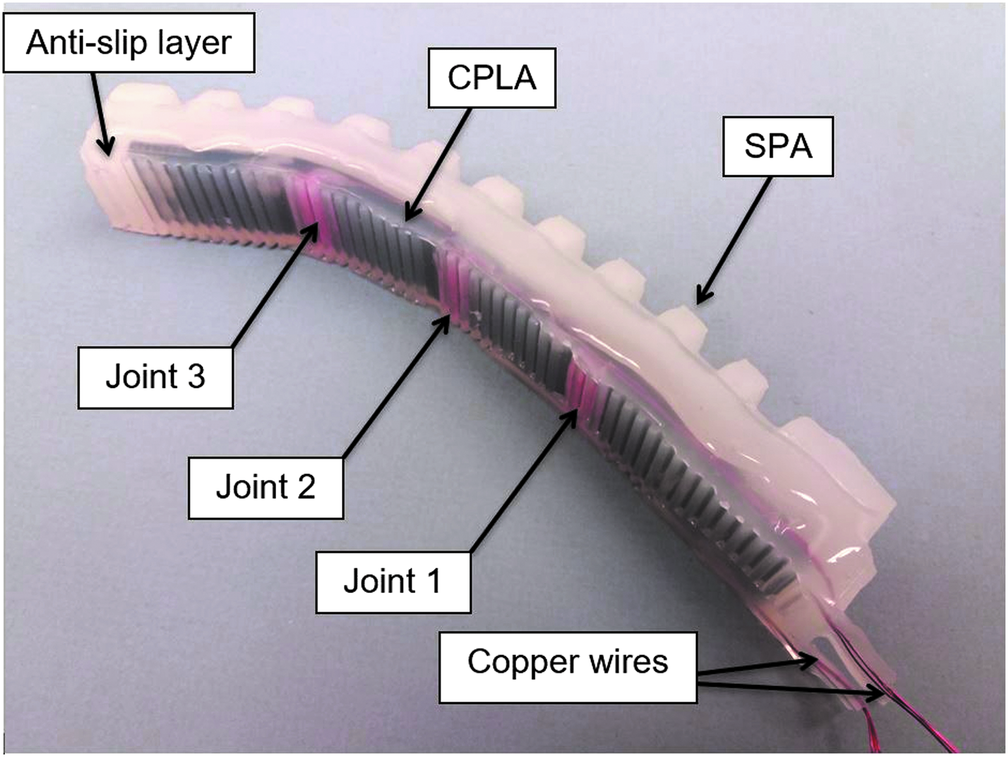
A fabricated SPA prototype with an embedded CPLA layer.
The Dimensions of Parts in the Fabricated Soft Pneumatic Actuator with Embedded Conductive Polylactic Acid
CPLA, conductive polylactic acid; SPA, soft pneumatic actuator.
Characterization of the Thermomechanical Properties of CPLA
In this section, the thermal, mechanical, and electrical properties of 3D-printed CPLA samples are characterized, for the purpose of modeling, simulation, and analysis that will be presented in later sections.
Glass transition temperature
The Tg is an important thermal property of polymers. The usual state of most polymers is hard and brittle at the room temperature and soft at the temperatures above Tg. 30 Differential scanning calorimetry (DSC) Q2000 from TA Instruments (Wilmington, DE) was used for determining the phase transition of the CPLA material. The following temperature conditions were used: heating from 35°C to 185°C at a rate of 10°C/min. The DSC curves for the test sample of the CPLA are shown in Figure 4. A phase transition that sets in at 55°C during the heating corresponds to the glass transition process when the polymer transforms to the highly elastic state. Two endothermic peaks observed at 124.4°C and 154°C correspond to melting. 31 Different melting temperatures were also observed in Ref. 32 due to the variation of size and level of perfection of the crystalline lamellae.

Differential scanning calorimetry curve for the CPLA. 28
Temperature-dependent stiffness
The stiffness of CPLA can be modulated with temperature. To measure the decrease in stiffness as a function of temperature, the tensile testing machine model SFM-20 (United Testing Systems, Inc., Fullerton, CA) was used. The Young's modulus at different temperatures (25°C, 35°C, 45°C, 50°C, 55°C, 60°C, 65°C, 70°C, 75°C, and 80°C) was measured. The specimen geometries followed specifications outlined in ASTM D-638 for the Type I tensile specimens. All samples were printed with a thickness of 2 mm. A loading rate of 3 mm/min was selected for all tensile tests. The tension specimens were tested in batches of five for each temperature point, and the values of Young's modulus were averaged over the five trials. The Young's modulus was calculated from the stress–strain ratio below the proportional limit of the material. One stress–strain graph under all 10 temperatures is shown in Figure 5. Figure 6 shows the decrease of Young's modulus with temperature where a significant drop in modulus in the range of 55–70°C is observed. This temperature range correlates to the region where the molecules undergo a transition from the glassy state to the rubbery state.

Stress–strain curves for all temperature points. 28

The decay in Young's modulus as a function of temperature. 28
Thermal expansion coefficient and thermal conductivity
Thermomechanical analysis (TMA) is a widely used technique to measure dimensional changes of solid or liquid materials as a function of temperature. This method can be used to measure the coefficient of thermal expansion (CTE) for polymers. 33 TMA was performed with TMA Q400 from TA Instruments on samples with dimensions of ∼12 mm × 12 mm × 1.7 mm. The samples were tested from the room temperature to 80°C at a heating rate of 3°C/min. Figure 7 shows an apparent change in slope at Tg, indicating an increase in thermal expansion coefficient above it. The CTE of the CPLA is the slope of the relative dimension change with respect to the temperature change divided by the initial sample height. The values of the CTE below and above Tg are 169 and 420.16 μm/m°C, respectively.

Thermomechanical analysis curve for the CPLA. 28
Thermal conductivity describes the ability of a material to conduct heat. The instrument NETZSCH LFA 447 NanoFlash® was used to measure the thermal conductivity of the CPLA. Using the multiproperty measurement capabilities of the NanoFlash, both thermal diffusivity
The density of the conductive PLA is 1.21 g/cm3. Three samples of dimensions 12 mm × 12 mm × 2 mm specimens were 3D printed, and for each one, five measurements were taken. The average of the five measured values for each specimen is shown in Table 2. It can be observed that for all the three cases the standard deviations were reasonably small.
Average Thermal Diffusivity and Thermal Conductivity Values for Three Samples
SD, standard deviation.
Electrical conductivity and Joule heating
Since the proposed CPLA joints are activated electrically, it is of interest to characterize its electrical conductivity and understand the heating and cooling dynamics. Consider a rectangular CPLA sample, assumed to have a uniform temperature
where
Experiments were first conducted to characterize the electrical resistance as a function of temperature. Figure 8a shows a schematic diagram of the experimental setup. A thermo-electrical generator (TEG) (model number CP081030-M; PELTIER) was used to control the temperature of the CPLA, and a resistance temperature detector (model number PTFM102T1G0; TE Connectivity) was attached to the CPLA sample with a thermally conductive paste for temperature measurement. The control of TEG and the data acquisition were coordinated with a microcontroller (model number A000073; Arduino). A CPLA sample with dimensions of 10 mm × 10 mm × 2 mm was used in this test. The samples were tested in the range from the room temperature to 55°C. At each tested temperature, the resistance of the CPLA is measured through a voltage divider circuit.

Figure 9 shows the measured resistivity as the temperature is raised and then lowered. One can see the hysteresis between the resistance and the temperature change, which is a nonlinearity commonly observed in phase-change materials. Since the hysteresis is relatively small, a linear fitting is found to capture the temperature-dependent resistivity, and such a linear approximation enables one to obtain an analytical solution to Equation (2), which is important for computational efficiency of the model. The validity of the linear approximation is confirmed by the good fit between the experimental measurement and model prediction later shown in Figure 10. The linear fitting between the resistivity R0 and the temperature
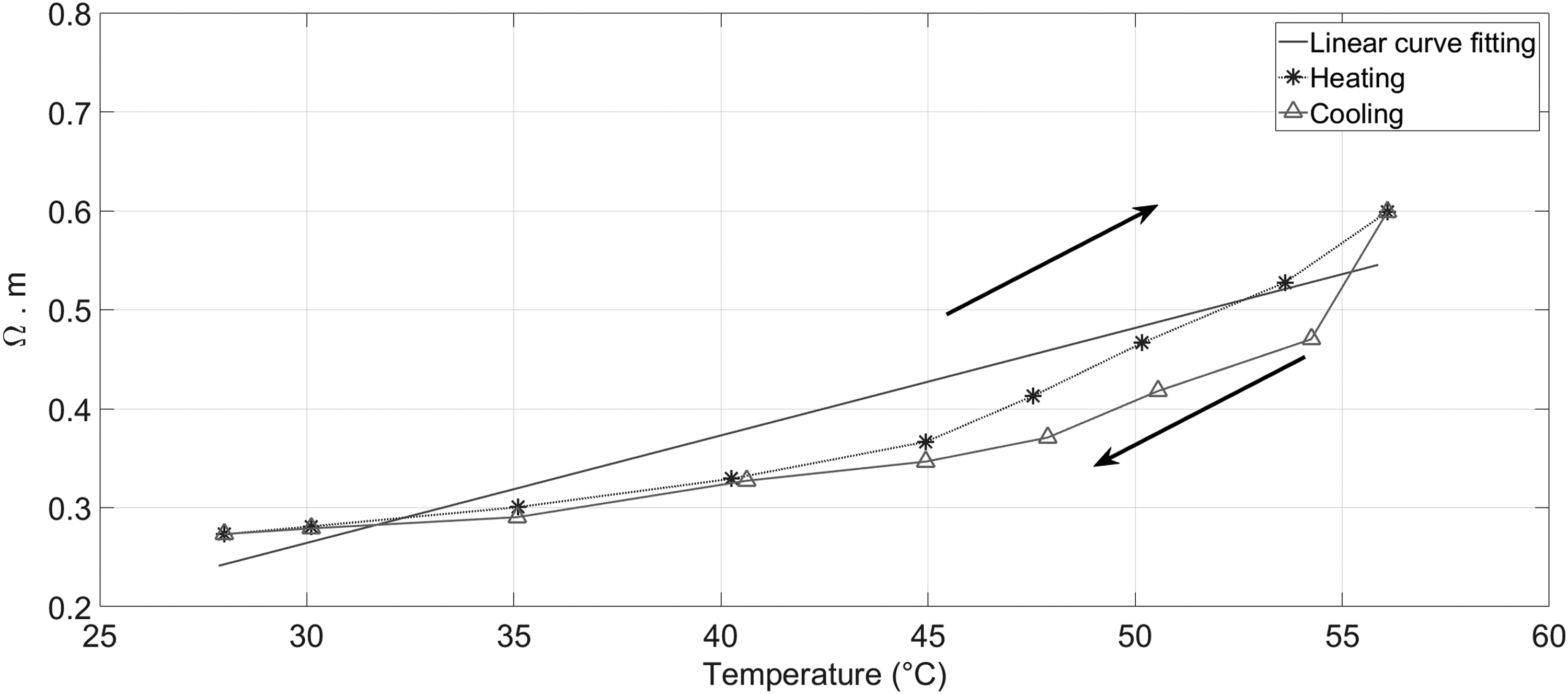
Measured resistivity of CPLA as the temperature is increased and then lowered. The linear line represents a linear approximation of the resistivity–temperature relationship.

Measured and model-predicted temperature evolution of the CPLA sample under Joule heating (50 mA) and then natural cooling in air.
Another test was an experimental setup illustrated in Figure 8b which was performed to measure the activation time for the CPLA to reach the Tg in Joule heating and the time it takes the CPLA to cool down passively to room temperature. For this purpose, a power amplifier (model number BOP 36-6D; KEPCO) was used as a current source. A current of 50 mA was applied to activate the CPLA while the temperature at the middle of the CPLA sheet was measured. Once the temperature reached the Tg, the current was turned off and the CPLA cooled down passively. This experiment was repeated five times. Figure 10 shows the evolution of the measured CPLA temperature along with the prediction from Equation (2) during the heating and cooling process. It can be seen that, with the experimentally characterized material parameters, the model is able to capture the heating and cooling behavior well. For this particular sample, passive cooling from the Tg to room temperature took ∼120 s. While the heating speed can be controlled with the applied current, the cooling speed is limited by the speed of heat dissipation to the ambient environment. The cooling speed, however, is a function of the geometry and dimensions of the CPLA sample. For example, Figure 11 shows the simulated cooling trajectories of CPLA samples of different thickness values, where the length and the width of each sample were fixed at 10 mm by 10 mm. From the figure, one can see that the cooling time could be significantly shortened with a thinner CPLA. For real robotic applications, proper dimensions of CPLA need to be designed to accommodate the corresponding load-bearing and speed requirements. For speed-critical applications, one could potentially adopt active air or liquid cooling by embedded fluid channels.

Simulated temperature trajectories of CPLA samples under natural cooling. The samples are assumed to have the same length and width (10 mm by 10 mm).
Finite Element Modeling and Simulation
The characterized mechanical, electrical, and thermal properties of the 3D-printed CPLA material are essential for understanding and predicting the behavior of CPLA-embedded soft actuators. As already shown in Characterization of the Thermomechanical Properties of CPLA, the measured electrical and thermal properties can be used to construct low-order dynamic models to predict the time response of Joule heating and cooling of CPLA. In this section, we use these material properties to create finite element model of a SPA integrated with the CPLA and examine its actuation response when individual CPLA virtual joints are activated, which will be further validated with experimental measurement. Such actuators will also serve as fingers for the robotic gripper to be discussed in Application to Grasping: Posture Reconfiguration and Shape Holding.
The finite element modeling analysis is conducted using the ANSYS Workbench. Three modules from ANSYS toolbox are used to conduct the simulation. The first one is the electrical system, which is used to compute Joule heating using the electrical resistivity of CPLA and the current applied to the CPLA hinges. The electrical analysis solution data are then passed as a load to the steady-state thermal analysis simulation, using an imported load to generate a temperature distribution profile for the actuator. The last module is the static structural system, where pressure on the inner walls of the actuator chamber can be specified to simulate the pneumatic input.
Two materials of interest are the CPLA and the silicone material (Dragon Skin 30; Smooth-On) for the soft actuator. The properties of CPLA used in the simulation are listed in Table 3. To characterize the material properties of the silicone, a uniaxial tensile test was performed following the D412-15a standard. The dumbbell test pieces were stretched at 500 mm/min. Five samples were stretched using a tensile tester (Universal Testing Machine 3345; Instron), and the average data obtained from the five samples were used in the finite element method (FEM) analysis. The averaged stress–strain data were fitted with the Ogden hyperelastic model,
36
which takes the following form for its strain energy function:
Conductive Polylactic Acid Parameters Used in Simulation
This model was used in fitting the experimental data of the mechanical tests in the strain range of (0–250)%. The least square curve fit was used to determine the parameters for each stress–strain data using ANSYS Workbench. The Ogden model proved to be the best constitutive model with parameter values
In the simulation, an electric current is applied to the hinges, and the air pressure is directly applied to all the walls of the pneumatic chamber. Figure 12 shows the temperature distributions at the steady state for both the CPLA layer and the SPA integrated with the CPLA, where the applied current is 60 mA and no pressure applied. The steady-state bending behaviors of the actuator under different air pressures obtained with the FEM simulation are illustrated in Figure 13. Pressure values of 4 psi, 8 psi, 12 psi, 16 psi, and 18 psi are applied in the simulation while different hinges are activated with Joule heating. In particular, it can be seen that, for each case, the actuator bends most appreciably around the location of the activated joint(s) while the remaining parts stay almost flat due to the rigidity of CPLA at the room temperature. Furthermore, for each configuration of activated hinge(s), the bending increases with the pressure applied to the actuator. The simulation results suggest that different bending shapes can be obtained through activating CPLA at proper locations, while the bending amplitude can be modulated with the pressure input. These observations will be further validated with experimental results in Experimental Model Validation.

Simulated temperature distributions from the FEM thermal analysis for

Simulated bending of the soft actuator under different pressure inputs, when
Experimental Model Validation
The SPA with embedded CPLA was clamped to an aluminum bar for testing the bending when different CPLA joints of the actuator were activated. For each configuration, a set of pressure values (4 psi, 8 psi, 12 psi, 16 psi, 18 psi, 20 psi, and 24 psi) was applied to the SPA. A pneumatic platform (Fluidic Control Board; Paradox Robotics™) 37 was used in combination with an integrated data-flow software (LabVIEW; National Instruments) to control the SPA inner pressure. To activate a given CPLA joint, a voltage of 12V was applied for over 2 min so the current could reach its steady state (around 60 mA). The temperature of each joint was measured using an infrared thermometer gun. Since the CPLA was encapsulated with silicone, the steady-state temperature detected at each joint was close to the CPLA Tg value (58°C). Figure 14 shows the snapshots of the SPA with embedded CPLA, when different values of pressure (vertical axis) were applied to the SPA, for a given configuration of CPLA joint activation (horizontal axis). The snapshots were taken at the steady state of each configuration.

Snapshots of the CPLA-embedded SPA under different pressure values, when different CPLA hinges were activated. Each column shows the achieved shapes with a given configuration of hinge(s), under the pressures ranging from 4 to 24 psi (top to bottom). Four hinge activation configurations were used: individually activating joints 1–3, respectively, and activating all joints simultaneously. The red circles in each picture indicate the locations of activated hinges.
To quantitatively compare the results from FEM simulation and experiments, we define bending angles at the joints (
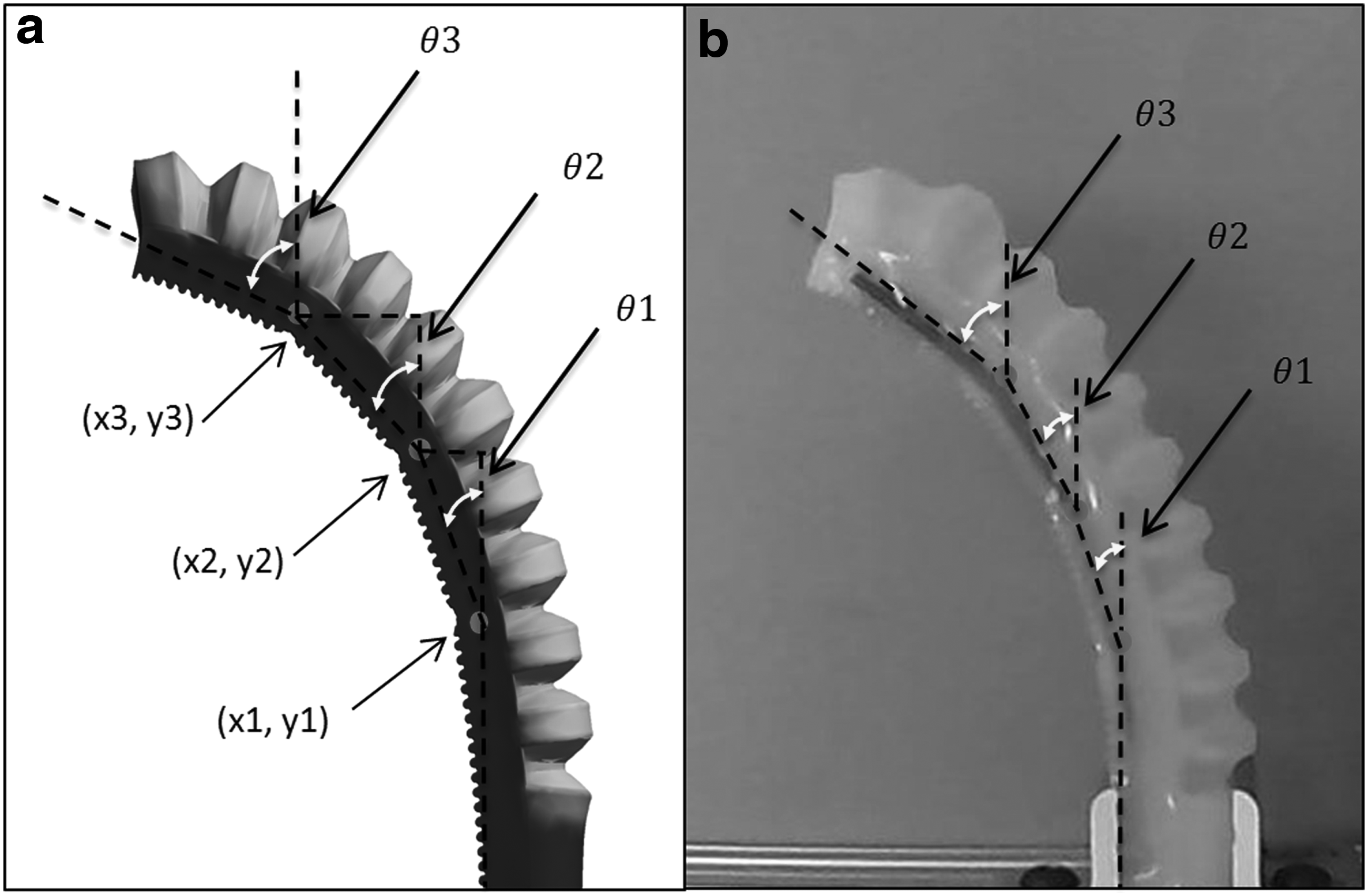
Illustration of the bending angles at different hinges:
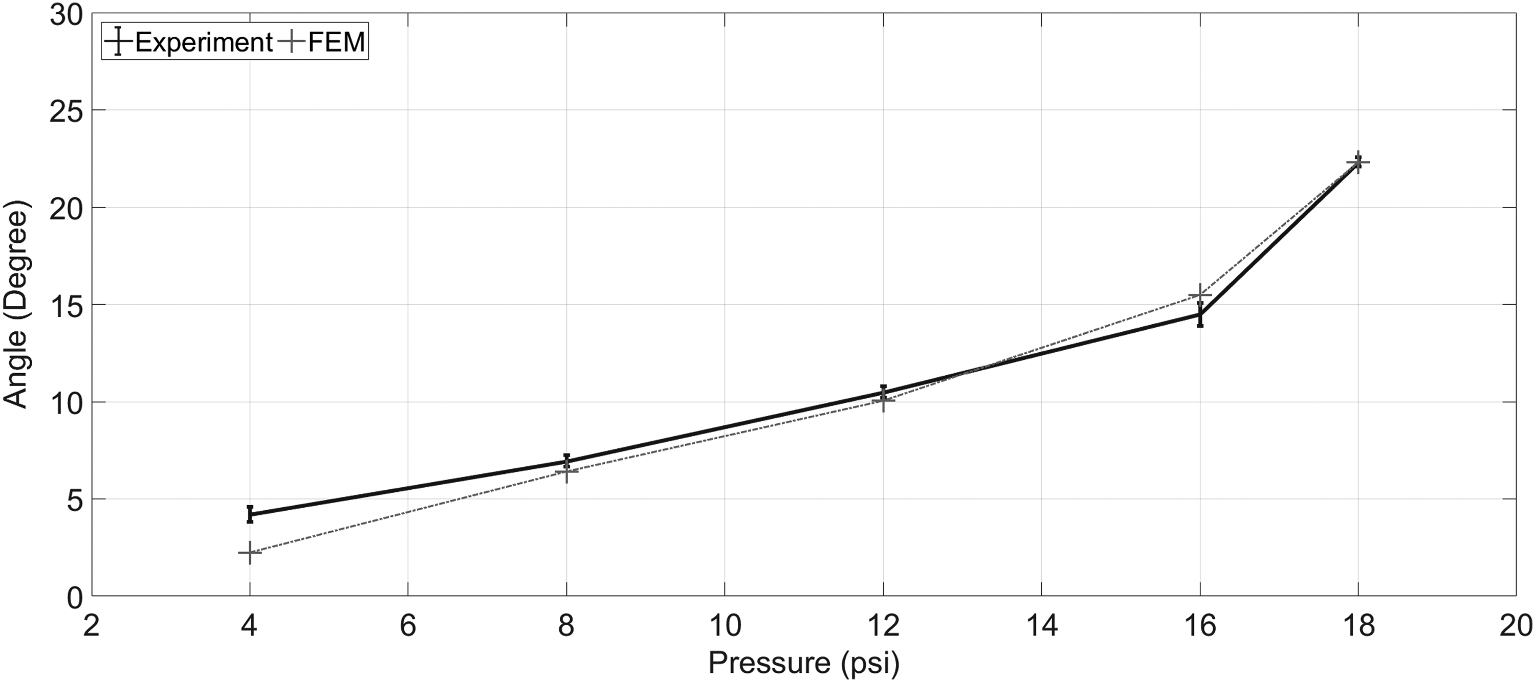
Comparison between model-predicted bending angle

Comparison between model-predicted bending angle

Comparison between model-predicted bending angle
Application to Grasping: Posture Reconfiguration and Shape Holding
Additional experiments were conducted to test the CPLA-embedded SPAs in a two-finger gripper configuration. The stiffness modulation in each finger could be controlled independently, allowing the generation of different bending angles to suit the shape of the object being manipulated. Multiple objects with various shapes and hardness were tested, where different grasping modes (e.g., scooping, pinching, and grabbing) were executed. In Figure 19a–c, the soft gripper was holding a plastic container using the aforementioned modes, while in Figure 19d and e, a soft mini football and a plastic cup filled with candies were lifted. For Figure 19a–d, all joints in both fingers were activated, while for Figure 19e, the left finger had all joints activated and the right finger had only the joint closest to the clamped end activated. All experiments were performed with a constant pressure of 20 psi for both fingers. Note that in these trials, CPLA enabled local shape reconfiguration of the actuators for the execution of different grasping modes.

Grasping of multiple objects using different grasping modes. A plastic container was grasped using
To evaluate the payload capacity of the SPA integrated with CPLA, several weights were placed inside a plastic container, which was being held by a single finger. The masses ranged from 50 to 500 g (Fig. 20), and the total carried weight was increased in increments of 50 g. The tests were performed for a minimum of 50 g and a maximum of 800 g. Figure 21a and b show the case where the SPA was actuated with a constant pressure of 22 psi while all hinges were activated (with a 12V input). Experiments were further conducted to evaluate the load-carrying capacity of the conductive PLA-embedded SPA when the actuation inputs were removed after it had achieved a given actuated shape. Specifically, the SPA was initially actuated with a pneumatic input of 24 psi, with all CPLA joints activated; with the pressure still on, the voltage input to the CPLA joints was removed to cool and “lock” the joints; once the CPLA joints were cooled down to the room temperature, the pressure input to the SPA was removed. Weights were then added to the SPA finger in this passive state (Fig. 21c, d). As shown in Figure 21, for both active and passive states, the soft finger was able to withstand the maximum payload of 800 g without causing any device failure or dropping the weights. The small difference in both shape and load-carrying capacity between the active and passive configurations is particularly important for applications that involve holding given postures for long periods of time, because one could use the passive configuration to save energy (without the need for pressure and electrical inputs) without compromising the performance. Note, however, that one needs to first actuate the SPA and activate the CPLA to achieve a desired shape before deploying the passive configuration.

Metallic weights (50–500 g) used during the single-finger holding experiment.

Testing load capacity of the SPA integrated with CPLA for both the active state and the passive state. A single-finger SPA-CPLA holding
Conclusion and Future Work
Selective stiffness modulation is highly desirable for soft robots since it will allow for more controllable and versatile performance in practical applications. In this work, a novel approach to stiffness control of soft actuators was achieved using a conductive PLA material conveniently printed with an FDM 3D printer. The stiffness of CPLA can be modulated by simply applying electrical power to areas of interest. The basic thermomechanical and electrical properties of 3D-printed CPLA were investigated experimentally. The results were then used in FEM simulation of a SPA embedded with CPLA, where three hinges (places where electrical voltage could be applied) were used throughout the article as a case study. The simulation results on the bending behavior of the actuator showed good match with experimental measurements conducted on a prototype. Finally, a two-fingered gripper, composed of two CPLA-embedded SPAs, demonstrated the ability to change the grasping posture to suit the shape, size, and texture of the objects being grasped. Furthermore, the SPA showed that it could be effectively locked in a desired bending configuration while carrying a weight even in the absence of pressure or voltage input. We note that although CPLA could reach 55°C or higher during operation, since it is embedded in silicone, an excellent thermal insulator, overheating or burning risk to the gripped objects is minimal.
Aside from providing a method for tuning shape and stiffness of soft actuators in general, this work contributes to the body of work on soft pneumatic fingers in particular. First, typical pneumatic fingers (e.g., the PneuFlex actuator-based fingers 38 ) use a single pressure input (thus a single degree of freedom for shape/grasping control). A CPLA-embedded SPA, on the other hand, allows the finger to have multiple points of active articulation with minimal added complexity and footprint. Second, the stiffness-tuning property of CPLA enables the finger to have reconfigurable stiffness, to adapt to different grasping tasks.
This article was focused on demonstrating the capability of stiffness and shape tuning, where some given voltage inputs were applied at the hinge locations. With the nature of thermal activation, we anticipate the proposed approach to be used for relatively low speed applications (1 Hz or lower). For future work, closed-loop control of the hinge stiffness, through the control of electrical voltages at different hinges, will be investigated, to achieve a more arbitrary desired shape for the SPA under a fixed pressure input. The feedback could be provided by integrating miniature temperature sensors at the hinge locations or potentially exploiting the strain-sensing capability of CPLA. In addition, it will be of interest to examine the joint control of the pressure input and the electrical inputs, to realize an even broader range of shape changes. Finally, in this work grasping was only used as a proof of concept for the CPLA-enabled shape control. Another direction of our future work is to examine the optimal activation of CPLA-enabled finger joints for handling different objects.
Footnotes
Acknowledgments
This work was supported, in part, by the Office of Naval Research (N000141512246), MSU Foundation Strategic Partnership Grant Program (16-SPG-Full-3236), Coordenacáo de Aperfeiçoamento de Pessoal de Nĺvel Superior (CAPES) under the Science Without Borders program (BEX-13404-13-0), and the National Science Foundation (DBI-0939454). The authors thank Drs. David Torres and Nelson Sepulveda for their assistance in the measurement of electrical conductivity of CPLA.
Author Disclosure Statement
No competing financial interests exist.