
Abstract
In the field of marine biology-inspired robotics, anguilliform locomotion, as one of the most common underwater propulsion types, has been widely studied and implemented in many robot prototypes. Most of these robots consisted of rigid parts, and they were able to generate smooth sine waves along the robot body using a great number of rigid segments, electric motors, and complicated control. To simplify the robot structures and improve body compliance, anguilliform robots with a full soft body are highly desirable for better biomimicry. In this article, we propose a serial soft-actuator array consisting of four fiber-reinforced, bidirectionally bending, fluidic elastomer actuators (FEAs) to achieve the generation of anguilliform body waves. The FEA is fabricated using the typical soft lithography method with dual-chamber configuration and fiber reinforcement. The bending performance of the single FEA in free space with static loads was measured and compared with the three-dimensional simulation results using the finite element method. After that, the FEA array was assembled using the through-chamber tube connection and tested in water to investigate the bending performance with dynamic loads. Finally, with coordinated control of each segment, this FEA array achieved the generation of anguilliform body waves with different frequencies and amplitudes, which unveils a novel and promising approach to develop an anguilliform underwater robot. By attaching this FEA array to a miniaturized stand-alone station for control and actuation, an untethered swimming robot was built and successfully propelled by the FEA array, which demonstrates the capabilities and potentials of this soft and slender robot body design.
Introduction
In recent years, the scientific and engineering communities have shown great interest in applying biological underwater locomotion to the marine robot for better performances in different marine missions such as search and rescue, Naval Intelligence, and Surveillance and Reconnaissance. 1 Compared with the conventional underwater vehicles driven by propellers, those bioinspired underwater robots have great potential to swim with higher efficiency, more agility, and less noise. 2 A great number of bioinspired underwater robots that make use of the different swimming strategies in marine animals have been developed. The most common propulsion strategies adopted are body/caudal fin (BCF) propulsion and median/paired fin (MPF) propulsion. To generate propulsion using body/fin, the robots are usually designed into slender fish-like bodies for BCF pattern3–6 or ray-like bodies for MPF pattern.7–9 Other propulsion strategies such as the jet propulsion using bell constriction 10 or mantel constriction 11 have also been successfully applied to underwater robots. Among those locomotion types, anguilliform swimming is among the most efficient swimming patterns because of low energy loss in wake separation.12–14 This highly efficient swimming pattern shows a promising future for developing more efficient and energetically durable underwater vehicles.
To mimic the anguilliform swimming, some eel-like/lamprey-like robots have been developed to achieve the anguilliform locomotion pattern by propagating waves along their slender bodies.15–17 However, most of the reported robots are made of rigid segments and conventional actuators like electric motors. For their locomotion, each of these rigid segments undergoes certain degrees of rotation. To form continuous and smooth waves, those rigid anguilliform robots require many segments with a complex control. Moreover, those rigid segments may limit body compliance significantly. To improve body compliance and simplify the body structure and control scheme, soft anguilliform swimming robots are desirable for better biomimicry. A soft robotic body, which incorporates the mature soft actuators, can potentially provide what was missing in the conventionally driven eel-like robots and achieve a more realistic anguilliform locomotion with high swimming performance.
Soft robots have drawn huge attention from the science community.18–20 Typical soft robots combine soft actuators and soft body components. Due to the great flexibility and infinite degrees of freedom from the innate softness of the material, 21 soft robots have been enabled to undertake challenging tasks in many different applications by utilizing a variety of custom-designed and fabricated soft actuators.22–24 Currently, these soft actuators can be divided into different categories according to their actuation principles.25–28 Typically, fluidic elastomer actuators (FEAs), as the earliest and most popular soft actuator type, have been widely used for their good compliance, high power-to-weight ratio, low cost, easy fabrication, and high customizability,29–33 and they have been designed into different shapes,34,35 diverse deformations,36–38 and varied levels of output force to meet the distinctive requirements for different applications.
Recently, a soft fluidic actuated robotic fish mimicking the rapid escape response of real fish has been developed by Marchese et al. 5 This robotic fish emulates the slender anatomical form of a fish with embedded compliant FEAs. Using the embedded FEAs, the robotic fish has been proven to have a similar escape response to biological fish. The improved version of this robot fish has now been able to swim freely in the marine environment and even record the aquatic lives. 39 The success of the FEA application in this robotic fish reveals the great potentials of FEA in underwater robotic applications. Therefore, FEAs, especially with fiber reinforcement, can be the ideal actuator for the development of slender soft robots to achieve anguilliform swimming. By virtue of their huge customizability, FEAs can be easily configured into a similar structure to the bodies of anguilliform swimmers.
In this study, we propose a soft actuator array consisting of four fiber-reinforced bidirectional bending FEAs for mimicking the body motion of the anguilliform swimmers that produce traveling waves along their bodies. The FEAs were designed and fabricated using the typical multistep soft lithography, and their assembly into a serial array was achieved using through-chamber tube connections to maintain its slender body and consistent body stiffness. The bending angles of FEAs in free space were measured and compared with the results from solving the three-dimensional (3D) quasi-static numerical models using the finite element method (FEM). With hydraulic actuation, the FEA array was tested in water and measured in terms of the bending angles of each FEA under dynamic loading, which guided the adjustment of the configuration of the hydraulic power. Using the mapping method, a series of anguilliform motions with different wave amplitudes and undulation frequencies were achieved. As a further step, an untethered swimming robot was built by combining our FEA array with a miniaturized stand-alone actuation station. Our FEA array successfully propelled the robot with a decent speed, which really paves the way for the advancement of the soft anguilliform robot.
FEA Design and Fabrication
The FEAs used in this work are designed with bidirectional bending capability as shown in Figure 1. Each FEA combines two semicircular elastomeric fluid chambers made of silicone rubber (Ecoflex 00-30; Smooth-On., Inc.), an inextensible layer between the two chambers, three flexible fluid supply tubes through each chamber, two caps (Dragon Skin 0010; Smooth-On) for sealing each chamber, and circumferential fiber winding for reinforcement. By individually pumping water into the chambers, the bidirectional bending motion can be achieved with the help of the constraint from the inextensible layer. For the serial FEA array, four FEAs are connected using a through-chamber tubing plan in which one tube connects the first chamber and the other three parallel tubes going through all four chambers and supplying water to the three posterior chambers, respectively, which guarantees a consistent bending stiffness of each FEA.

Structure of the FEA array.
Reports show that, for the typical eel-like body intended for anguilliform swimming, the width-to-length ratio of the body is about 1/8 and the beating amplitude of the tail tip is about 1/8 of the body length.13,40 During their anguilliform locomotion, at least one period of a wave is generated along their slender bodies. To ensure that the soft FEA array could lead to similar morphology, the parameters of FEAs were decided according to the biometric data of the real anguilliform swimming fishes. Specifically, the total length of each individual FEA is 60 mm. The inner diameter and the outer diameter of the chamber are 18 mm and 26 mm, respectively (wall thickness is 4 mm). The flat bottom of each chamber is set to 2 mm so that the shared middle wall between the two chambers can have a similar thickness. Two layers of cotton fiber (0.2 mm thick) reinforcement with 0.4 mm winding pitch were applied to the two chambers and secured by an extra 1-mm thick silicone coating as shown in Figure 1. The length of the sealing cap is 10 mm, and the inner and out diameters of the inserted flexible tubes are 2 and 4 mm.
Multi-Step soft lithography was used for the fabrication of FEAs as illustrated in Figure 2. The first step was to form an inner silicone bladder, which was molded using 3D printed molds (Fig. 2a). After that, the inner bladder, with inner chamber template remaining (Fig. 2b), was reinforced by adding two layers of cotton fiber windings using the winding machine as shown in Figure 2c. The fiber windings were then secured by molding another layer of EF-30 (thickness is 1.0 mm) using the second 3D printed molds (Fig. 2d). To limit the extension of the bottom plane, an inextensible layer (∼0.4 mm thickness with ∼400 MPa elastic modulus) was glued to the flat surface (Fig. 2e), which completed the half FEA. A second-half FEA was then glued to the inextensible layer from the other side (Fig. 2f). After inserting tubes into the two chambers and sealing the two-chamber ends, one whole FEA was fabricated.

Steps of the Bidirectional bending FEA fabrication process.
Static Characterization and Simulation
After the fabrication, we first investigated the bending performance of FEAs in free space to understand its static motion characteristics as the basic reference for dynamic motion generation. In addition, the nonlinear FEM models of FEAs were simulated to compare with the experimental results. Particularly, the tip displacements of FEAs from experimental measurements and simulation were analyzed to evaluate the amplitude of the waves to be generated by the FEA array.
Static bending experiment
Bending angles of FEAs in free space with different pressure loads were measured using the platform as shown in Figure 3a. During the experiment, one end of FEAs was fixed at the top with the other end left in free space. The pressure inside the FEA chamber was increased at the rate of 1 kPa/s by the motorized pressure regulator, during which a pressure sensor placed at the inlet of the actuator recorded the instantaneous pressure value. The bending angles (relative to the initial position) were measured (thrice for each FEA) on the recorded videos using a motion analysis software (Tracker, an open-source software). The measurement stopped at 150 kPa, at which the bending angle of FEAs reached about 120°. Beyond 150 kPa, the FEA was likely to buckle as the body volume of the inboard half FEA did not allow too big a curvature.

Measurement setup and bending sample FEAs.
Numerical modeling
3D FEM simulation (Fig. 4) was conducted to evaluate the bending behavior of the single FEA. Specifically, the static loading problem was modeled using the quasi-static method of dynamic explicit in Abaqus 2017 (Simulia; Dassault Systems). The details of the elements used for modeling the FEA are presented in Table 1. These material properties were fitted using experimental results, which have been reported by Sun et al. 33 To improve the speed of convergence, the silicone caps were simplified as rigid bodies due to its relatively much greater stiffness than EF-30. Tie constraints were applied for the interactions between the fiber winding and the chamber, the sealing caps and the chamber, the sealing caps and the flexible tubes, and the chamber and the inextensible layer. During the whole simulation, one end of the actuator was fixed, while other parts were free. For this 3D model, the natural frequency of FEAs was computed to be 11.65 (period T ∼ 0.086 s). Therefore, to ensure the simulation process to be quasi-static, a much longer loading time period t = 1.0 s (t > 10 T) was used for explicit processing. For the entire simulation, the maximum whole kinetic energy (ALLKE) was smaller than 1.0 × 10⁻⁴ of the whole inertial energy (ALLIE).

3D FEM model and simulation results of FEAs.
Numbers and Types of Elements Used for Finite Element Method Models
FEA, fluidic elastomer actuator.
In the quasi-static simulation, a uniform pressure (p) load was applied to the inner surfaces of the chamber, the inner surfaces of the sealing caps, and the inner and outer surfaces of tubes. The pressure load was increased from 0 to 150 kPa in 1.0 s, and the resultant bending angles were recorded in 100 spaced intervals. The examples of the bending shapes of FEAs at 30, 60, and 120 kPa are shown in Figure 4b, which are similar to the shapes of the actual FEA at the same pressure shown in Figure 3b. In the figure, the deformed FEAs were colored by the logarithmic strain (LE). As shown in the figure, elements of the chamber with the maximum strain are located at the external wall of the actuated chamber and around the inextensible layer.
Bending result comparison
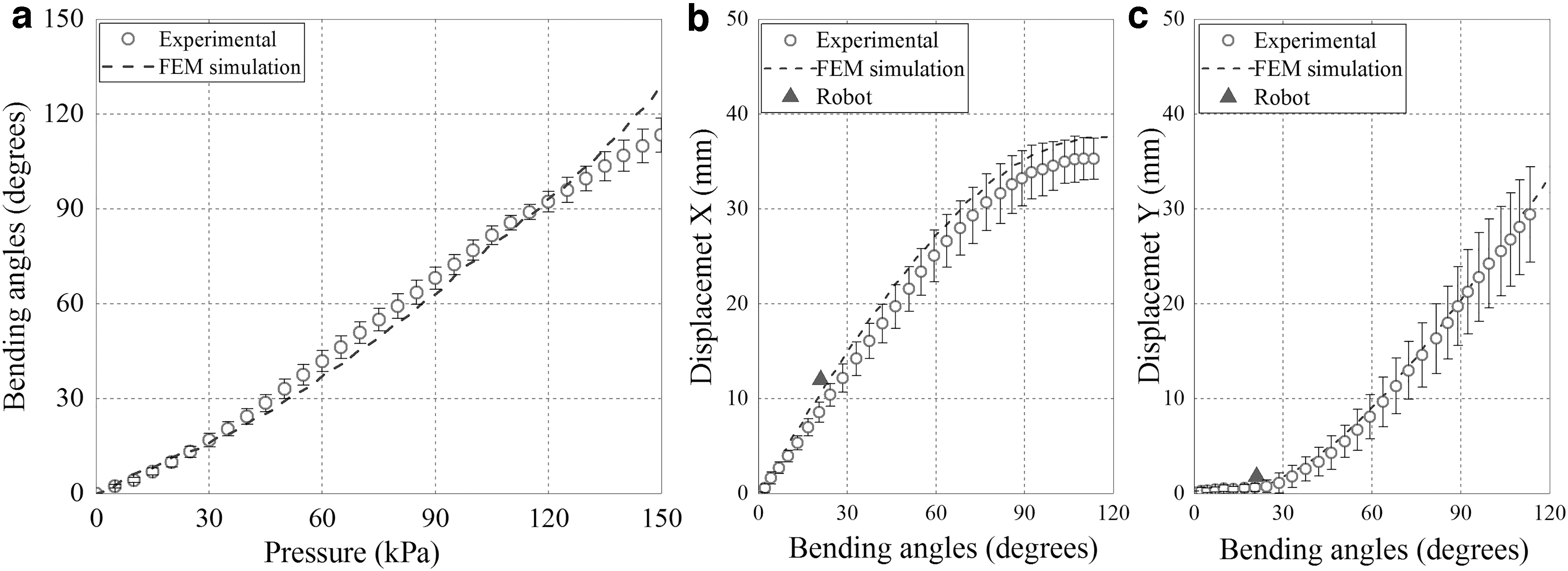
The experimental and simulation results of the bending angle and the tip displacement of FEAs are shown in Figure 5a–c, respectively. For all experimental results, the red circles represent the averaged value, while the error bars show the standard deviations of the measurements.
Results of FEAs bending in free space with static loads.
As shown in the Figure 5a, the bending angle of FEAs from experiments increases almost linearly from 0° to 110° as the pressure loads increase from p = 0 kPa to p = 150 kPa. The FEM simulation shows a similar increase although the slope of the bending angle curve increases slightly with the increasing pressure, which resulted in slight deviations when pressure approaches 150 kPa. The standard deviations of the measured bending angles are fairly small, which indicate the good repeatability of FEAs and the potential to simplify the control of the pumps.
The tip displacements were measured for the prediction of wave characteristics as the wave amplitudes are mainly related to the x-displacement, and the wavelengths depend on the y-displacement. As shown in the figure, the tip displacements in the x-direction increase linearly before bending angles reach 60°. The tip displacements in the y-direction are small for bending angles <30° and then linearly increase at bending angles >45°. Due to the quasi-linear relationship between bending angles and pressure loads (Fig. 5a), the displacements in the x-direction are almost linear with respect to the pressure loads for small bending angles. These characteristics are important for controlling the traveling waves on the FEA array in the wave design. For example, for bending angles <30°, the y-direction displacements are so small that the wave amplitudes of the FEA array can be linearly controlled by pressure loads with a nearly constant wavelength.
Dynamic Characterization
Based on the understanding of the preliminary performance of the FEAs from the static bending characterization, we continued to investigate the performance of FEA array (four FEAs connected) in water with dynamic loading.
Dynamic bending experiment
During the test, the FEAs in the array were independently actuated by four gear pumps (properties of the gear pumps are shown in Appendix A1). By modulating the pulse width modulation (PWM) signal and periodically changing the pump motor direction, the bidirectional bending of the FEAs with controllable frequencies and power was achieved. For the dynamic loads, the maximum bending angle of each FEA is limited by the total volume of the water in the two chambers. Specifically, at relatively low frequency and high pump power, the maximum bending angle will remain similar as all of the water has already been pumped into the outboard chamber. Therefore, the very low frequencies are not considered in the tests.
For the dynamic characterization experiment, each FEA along the FEA array was tested separately at frequencies f from 0.4 to 2.0 Hz and duty cycles P/P0 from 0.2 to 1.0 using the experimental setup as shown in Figure 6a. During the in-water tests, the FEA array was fixed with a truss frame until the anterior part of each tested FEA. For each testing configuration, FEAs were measured thrice. Figure 6b shows the four FEAs in the array at their maximum bending angels powered by f = 0.5 and p = 0.4 P0.

Measurement setup and bending samples of FEAs with dynamic loads.
Bending results
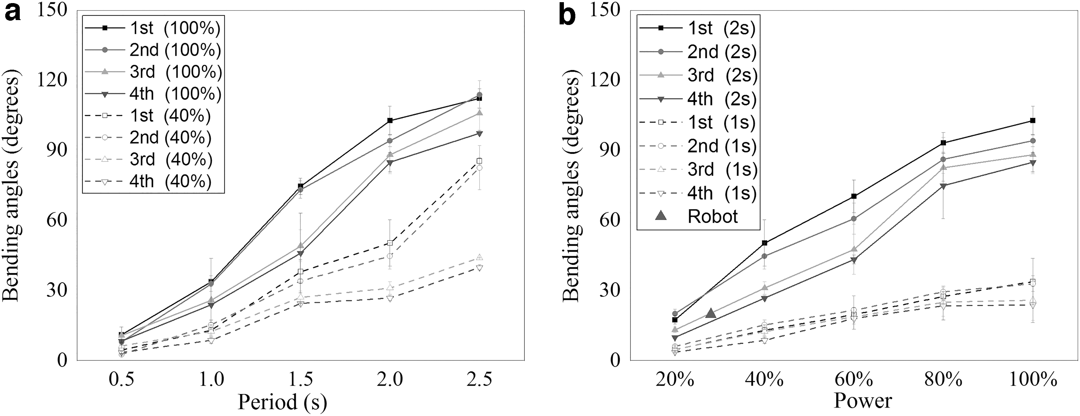
Figure 7 shows the averaged bending angles of the four FEAs in the array under different dynamic loads with the error bars indicating the standard deviation. Figure 7a illustrates the relationship between the bending angle of FEAs and the period (T) of the pump, which gives the overall increasing trend of the bending angles of the FEAs powered at 0.4 P0 and 1.0 P0. Figure 7b illustrates the relationship between the bending angles of FEAs and the power of the pump at two frequencies. For the given frequency, the bending angles of FEAs are found to increase with the increase of the pump duty cycle.
Results of FEAs bending in water under dynamic loads.
As shown in Figure 7, the first and the second FEAs usually bent with greater angles than the other two FEAs, especially at increased pump powers and periods. The major reason for the difference in bending angles along the FEA array is the effective length of the fluid supply tube. To investigate this influence, the pressure loss and the flow rate from the pumps to the actuated chambers were measured with pumps connecting different lengths of inlet/outlet tubes and two pressure sensors measuring the fluid pressure right outside the pump outlet and at the end of the tube (Appendix Figure A2-a). The detailed results (Appendix A2) show that the pressure loss in the outlet tubes increases almost linearly with the increase of the tube length, which certainly reduced the flow rate from the first FEA (∼25 g/s) to the fourth FEA (∼16 g/s). Therefore, during the underwater bending of FEAs, the pressure and flow rate arriving at the rear chambers are smaller than the values in the first chamber, resulting in reduced bending angles as shown in Figure 7.
Another reason for the bending angle difference is the inertia. As the internal driving forces of FEA reduced to zero when pumps changed directions, the inertial forces are greater than the internal forces which usually drive the FEA body for some extra angles, especially in testing the first and second FEAs which carry heavier FEA bodies. This inertia induced angle difference is found to be larger as the period increases since the longer period could contribute to more accumulated kinetic energy in the FEA array. However, as shown in Figure 7a, this trend was not strictly followed with bending angle >90° (1.0 P0 and T > 2.0 s) because, at high bending angles, the bending of FEAs became irregular with a certain level of buckling.
Overall, the dynamic characterization of FEAs in the FEA array provides practical information to configure the power of the individual FEAs along the array to get smooth and uniform traveling waves. More importantly, we are confident that the anguilliform waves can be generated using the four FEA arrays as the bending angle results in the in-water dynamic tests, ranging from 5° to 90°, represent a feasible and comfortable frequency range from 0.4 to 2 Hz and decent amount of amplitudes (1.7–33.3 mm) and wavelength (240.0–160 mm).
Traveling Wave Generation
With the results in the dynamic loading experiments, we can simply use the mapping method to configure the pump powers and generate anguilliform locomotion with desirable waves. In wave generation, each FEA in the array worked as a segment with a phase lag of T/4. With the four segments bending periodically, sine waves were formed and transferred from the head to the tail continuously. The control signals for powering FEAs are shown in Figure 8 with Figure 8a giving the filtered sine signals for the four FEAs in the array and Figure 8b–e showing the corresponding transferred PWM signals for the four gear pumps. During anguilliform wave generation, the parameters of the locomotion, including the beating frequency, the amplitude, and the wave envelope along the body, were controlled through properly adjusting these four PWM signals.

Control signals of four gear pumps.
The wave generation on the FEA array was implemented in the setup shown in Figure 9, in which the robot was placed vertically in the water and the fluid supply tubes were fixed at a point above the water surface. The density of the silicone is 1.07 g/mm3, which makes the FEA array after filling with water slightly denser than water. Such density not only ensures that the motions of the FEAs will not be affected by gravity in the vertically-oriented fixation but also allows the body to remain in the vertical orientation instead of drifting around. The generated waves from this orientation are therefore also reproducible in other orientations, which reflect another merit of the proposed silicone-based FEAs in underwater robot application. The FEA array started the undulation from the head to the tail in the first cycle. Since the tubes ahead of the head were fixed, the beating amplitudes of the first segment were limited, and the beating amplitude at posterior segments was amplified with the accumulation of the amplitude of the anterior FEAs. This increased-amplitude body wave envelope was coincident with the increased-amplitude wave envelope that was observed on anguilliform swimmers.

Setup for the anguilliform waves' generation.
In the experiment, the anguilliform wave generation using the proposed setup only considered period under 2.5 s and power under 0.8 P0 because of the twisting of the FEA array. For the undulatory moving FEA array, FEAs were bent in the tank as shown in Figure 9 with a moment component normal to the plane. The moment component came from the nonuniform stiffness of FEA as one of the three in-chamber tubes was actuated. Examples of the anguilliform locomotion with different beating amplitudes and frequencies are shown in Figure 10. The deformed shapes of the FEA array were captured in one beating cycle with a constant phase lag of T/4. The midplane of the robotic prototype was outlined with solid curves, and the tip displacement of each FEA was measured. Figure 10a–c shows the shapes of the robot with small amplitudes (0.4 P0 and 1.0 s), medium amplitudes (0.4 P0 and 2.0 s), and large amplitudes (0.8 P0 and 2.0 s), which give tail beating amplitudes of 10.0, 33.0, and 46.5 mm, respectively. Figure 10d shows the tail beating amplitudes of all tested configurations. The detailed tip beating amplitudes of the four FEAs are presented in Appendix A3. A video of the generated traveling waves is attached in Supplementary Video S1. The midline of the robot at t = T + 0.75 T in Figure 10b is highlighted in Figure 10e. By combining the midlines from Figure 10b, we can see the overall undulation of the FEA wave.

The traveling waves generated with the soft robot.
As shown in Figure 10d, the smooth anguilliform wave can be generated using this FEA array with tail beating amplitudes from 10.0 mm (1/24 wavelength) to 46.5 mm (∼0.2 wavelengths). For traveling waves with amplitudes smaller than 10 mm, the undulation of the body was very small and was not recorded. As shown in Figure 10b, the tail beating amplitude of the undulating FEA array increases fairly linearly with the pump power at different periods, while the period has a stronger influence in the amplitude despite the irregular curve of 2.5 s period.
For the case shown in Figure 10b, the tail beating amplitude At = 33.0 mm (33.0/240.0 wavelength) was close to the tail beating amplitude (1/8 wavelength) of the eel-like animals.13,40 At this moment, the amplitude of the cosine wave had its maximum value of A0 = 12.0 mm, and the bending angle of the four FEAs was α = 21° (Fig. 10e). The trajectory of the tail tip in this beating cycle was measured and illustrated using the red curve in Figure 10e, which shows a similar structure of the trajectory from a real anguilliform animal. 40
Before comparing the bending of a single FEA and FEAs in the array, the body inertia and the hydrodynamic forces on the FEA array were investigated to understand their influence in the array undulation. The internal driving forces (tip bending force) of the single FEA had been measured with internal pressure increasing from 0 to 100 kPa at three angles: 0°, 30°, and 60°. The detailed force curves are presented in Appendix A4, which shows that the tip bending forces were 3.0–4.0 N when the FEA was actuated by 100 kPa pressure. The body inertia and the hydrodynamic forces were evaluated using the fictitious force and the drag force (Eqs. 1 and 2). Since the fourth FEA in the array would have the maximum acceleration and velocity, the corresponding maximum forces of the fourth FEA were calculated. The displacements, velocities, and the accelerations of the fourth FEA in undulation case of t = 1.0 s and p = 0.8 P0 are presented in Appendix A4. The maximum fictitious force and hydrodynamic force acting on the fourth FEA were 0.019 and 0.017 N, respectively, which means that, at most times, their influences are negligible. Therefore, the single FEA test results can be used for the generation and analysis of the undulatory motion of the FEA array.

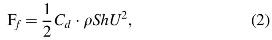
where Fi is the fictitious force, m is the mass of the segment, ax is the lateral acceleration, ρ is the density, V0 is the volume of the segment, l is the length along the segment, F f is the fluid drag, Cd is the drag coefficient, S is the surface area of the segment, h is the overall length of the segment, and U is the velocity of the bending segment. For the given case, maximum U is 0.1 m/s, h = 0.06 m, and the corresponding Reynolds number is 6 × 10³. For finite-length cylinders, the Cd is about 0.7.
To investigate the relationship between the performance of the FEA array and bending characteristics of an individual FEA, we compared a generated anguilliform wave (Fig. 10b) with the measurement results of FEAs in the former sections. For this specific case, the third and the fourth FEAs were powered by pumps with T = 2.0 s and p = 0.4 P0. To ensure that all FEAs bend with similar angles, the first and second FEAs were given reduced power (p = 0.7 × 0.4 = 0.28 P0) based on the results in Figure 7. The shapes shown in Figure 10b are the robot at the time point 1–4 as shown in Figure 8a, respectively. As shown in Figure 8a, when the midplane of the robot moves as the sequence shown in Figure 10b, the power of the pumps connected to the third and fourth FEAs was p = 0.7 × 0.4 P0. According to the parameters of the pumps, the bending angles and tip displacements of FEAs can be predicted using Figures 5 and 7, respectively. Thereafter, for comparison, the measured values are marked as the point “Robot” in Figures 5 and 7 from which we can see that the overall robot movement follows the FEA bending characteristics. As shown in Figure 7b, the measured bending angle of the FEAs in FEA array α = 21° was close to the predicted bending angle from the curve of FEAs at p = 0.28 P0 and t = 2.0 s. The tip displacements are Ax = 12.0 mm in the x-direction and Ay = 1.8 mm in the y-direction, which match well with the predicted displacement from the curve at bending angle α = 21° (Fig. 5b, c).
During undulation, the FEA array would combine four bending motions from the connected four FEA segments with certain phase lags, which will incur certain displacement cancellation for the posterior three FEAs. To investigate such cancellation, the maximum bending angles and the maximum lateral tip displacements (in the x-direction) of the four FEAs were examined. For the experimental results, each value was measured more than thrice. For the case of Figure 10b (t = 2.0 s and p = 0.4 P0), the maximum bending angles of one to four FEAs in the array were measured as 31.3° ± 5.8°, 23.4° ± 3.4°, 29.2° ± 3.2°, and 25.7° ± 3.3°, respectively, which, despite some cancellation, are fairly close to the result (30°) of the first and second FEAs at 2 s T and 0.28 P0 and the third and fourth FEAs at 2 s T and 0.4 P0 according to Figure 7b. This means that those FEAs have similar bending characteristics when placed in the array.
However, for the maximum lateral tip displacement, the situation is different depending on the position of the FEAs in the array. For the first FEA, as the head was fixed, there was no cancellation for the tip beating, which is reflected by the match between the measured value (13.1 mm) and the value from Figure 5b at the bending angle of 31.3°. For the second, as the head oscillates with the beating of the former FEA, the maximum lateral displacement (9.8 mm) is slightly smaller than predicted values. On the contrary, for the fourth FEA, the maximum lateral displacement is much larger than the predicted value from Figure 5b (30° is about 14.0 mm), which is mainly resulted from the amplitude accumulation along the FEAs. As the combination of cancellation and accumulation, the third FEA has a maximum lateral displacement of 13.3 mm. These results indicate that this setup would limit the overall oscillation of the array at the head, while it would enhance the beating of the array at the tail.
The good agreement of the generated motion with the predicted values from experimental and FEM computational results of individual FEA validated the design approach presented in this study. This approach achieved the specific motion using customized soft actuators, which would provide information on soft actuator design for other biomimetic applications. For the FEA array developed in this study, apart from generating the anguilliform traveling waves along the slender body, it also has the capability to achieve other wave generation in BCF locomotion patterns such as thunniform waves. Simply by adjusting the phase lag between the neighboring segments below T/16, the total phase lag will be less than T/4, which can form the C shape in the thunniform waves.
Hydrodynamics of the Anguilliform Motion
Hydrodynamics of the generated anguilliform traveling waves with the FEA array is studied in this section using dye-injection experiments to visualize the flow around the FEA array. For the experiment, to minimize the influence of dye's gravity, the FEA array was placed in a horizontal plane and undulated laterally. According to the shapes of the traveling wave, 3D computational fluid dynamics (CFD) models of the motions have been simulated using the immersed boundary method in OpenFOAM. The simulation results matched well with the visualized flow around the undulatory moving array, and the simulation results also provide the detailed force generation and flow formation with the undulatory moving body.
Figure 11a and b shows the 3D model that simulated the undulatory moving FEA array. Parameters used in the simulation were chosen according to the experimental setups. The FEA array was modeled as an inextensible 3D rod with the diameter of 0.026 m and length of 0.240 m. The undulatory motion of the body as shown in Figure 11a and b follows the typical normalized anguilliform motion function (Eq. 3).

Flow around the undulatory moving FEA array.

where s is the normalized arc-length from the head (s = 0) to the tail (s = 1), x is the lateral displacement, A0, A1, A2 are the amplitude coefficients, and T is the period. For the case shown in Figure 11, T is 1 s, A0 = 0.0250, A1 = 0.0085, and A2 = 0.0498 to ensure the head, the mid-point, and the tail of the FEA array undulate with the same amplitudes as the values measured in the experiment which are 0.025 λ, 0.0417 λ, and 0.0833 λ, respectively.
The FEA array was laterally put in a 0.6 × 0.3 × 0.3 m water tank. Figure 11b shows the fluid domain in the same size as the water tank. The top surface of the fluid domain is a free inlet–outlet surface, while the boundary condition for other five surfaces is the no-slip wall. During the simulation, the FEA array was put in the same position as it was put in the experiment, and the undulation was linearly started in the first period. The entire simulation runs 10 cycles to ensure that the stable flow could be established. The details of the 3D model and grid-independent are presented in Appendix A5.
Figure 11 compares the simulation results with the experimental measurement of the flow around the FEA array. As shown in the figure, for the experiment, still dye was dropped into the tank at four points separately. The drop points are shown in Figure 11a and c. After several undulation cycles, the wake was formed. Figure 11a and b shows the lateral velocity and the magnitude of velocity in the x–y plane (FEA undulating plane) with the arrow directions and lengths representing the flow directions and speed magnitudes. As shown in the figure, the undulatory amplitude increases from the head to the tail. At the anterior parts, the wake separation is weak. There is almost no backward flow generated by the undulatory array. On the contrary, for the posterior parts, there is an obvious flow generated. Specifically, at P-1, the FEA segment at P-1 pushes the surrounding water laterally (Fig. 11a, b), so the dye dropped at this point would spread laterally (Fig. 11c-1). From the midpoint (P-2) to the tail, the water is pushed backward; the arrows in Figure 11a and b show the backward flow and their magnitude. The visualized flow also shows a similar pattern as shown in Figure 11c-2 and c-3. At the tail tip, as the tail beating with larger amplitudes, surrounding water is pushed in higher speed (longer arrows in Fig. 11a, b) and flows to the lateral directions with slight forward angles. The similar flow direction is visualized by dropping dye at the tail as shown in Figure 11c-4. Overall, the flow direction and pattern from simulation matched with the visualized flow in Figure 11c. For the movie of a dye experiment, please refer to Supplementary Video S2.
To investigate the mechanism of the flow structure formation, the vorticity field around the body has been computed as shown in Figure 12. Figure 12a and b presents the 3D isosurfaces of vorticity ||ωy|| = 2 which is colored by vorticity in the y-direction and ||ω|| = 2 which is colored by vorticity in the x-direction, respectively. Figure 12a shows that, as the body wave traveled from the head to the tail, there was a vortex formed and spread. At both sides of the tail, there are two serials of vortices shed slightly. This flow shows a similar structure to the wake of the real eel-like swimming animals. 40 The differences between the isosurfaces of vorticity (Fig. 12) and reported simulation results were the vortices shedding. For the real animals, as the body swims forward, two rows of vortex rings were shed from the tail. For our simulation results, since the body was fixed in a water tank, the vortices formed at the tail tip could not flow backward as the FEA array undulates. The flow formation and vortices spreading show the forward potential of the motion if the body is not fixed.

Formation of the flow structures visualized by plotting isosurfaces.
The forces acting on the FEA array from the surrounding water are shown in Figure 13. As the FEA array started the motion in the first undulation cycle, all forces showed a certain increase/decrease trend in the first several cycles. Those forces were fully established and oscillate in certain modes from the beginning of the fourth cycle. As shown in the figure, all viscous forces are much smaller than the corresponding pressure force. After the fourth cycle, the lateral forces would oscillate with mean values of 0. Pressure forces in the y-direction overcome the viscous drag and provide the thrust (-y-direction as shown in Fig. 11) for the body. The time-averaged thrust (3.26 × 10⁻³ N) validates the capability of the FEA array to generate forward motion.

Forces generated by the FEA array.
To investigate the influence of undulatory amplitude on force generation, 3D models undulated in 1.0, 1.5, and 2.0 s have been simulated. The motion parameters were chosen according to the generated anguilliform waves in Figure 10 (0.8 P0 in 1.0, 1.5, and 2.0 s). The head, midpoint, and tail undulatory amplitudes for those three cases are 0.0483 λ, 0.0271 λ, 0.0646 λ (1.0 s), 0.0623 λ, 0.0375 λ, 0.1271 λ (1.5 s), and 0.0954 λ, 0.0833 λ, 0.1938 λ (2.0 s), respectively. The time-averaged thrust for each case is 1.77 × 10⁻³ N, 2.27 × 10⁻³ N, 4.45 × 10⁻³ N. The result of these three cases shows the trend that the larger tail beating amplitude could contribute to larger thrust. By comparing the thrust generated by the body undulates with t = 1.0 s and p = 0.8 P0 with the thrust generated from the previous horizontal case, we find that a smaller head beating amplitude also contributes to larger thrust. The combination of a smaller head beating amplitude with a larger tail beating amplitude shows the optimal direction for developing the fast-swimming robot prototype.
Eel-Inspired Soft Robot Prototype
With detailed investigation and understanding of the FEA and the assembled array, an untethered eel-inspired soft robot prototype has been developed to examine the forward propagation capability of the FEA array. The robot, as shown in Figure 14, combines the FEA array with a miniaturized station, which incorporates pumps, battery, and control component, and a passive tail made of silicone rubber (Dragon Skin-10) connected to the end of the FEA array. The robot had been tested in still water with body undulates in t = 1.0 s (Supplementary Video S3), t = 1.5 s (Supplementary Video S4), and t = 2.0 s (Supplementary Video S5). Particularly, the robot undulation at 1 s period is given in Figure 15, from which we can see that the robotic fish generated and spread one body wave from the first segment to the fourth segment of the body in one undulation cycle. With the body wave traveling backward, the robotic fish swims forward in 2.88 cm/s. The corresponding mean forward speed is 0.12 L/s (body length/second), which is comparable with the swimming speed of the published rigid undulatory anguilliform robots but slower than the swimming speed of the real eel (∼0.6 L/s).13,40 For 1.5 and 2.0 s cases, the robotic fish swims with 5.45 and 4.08 cm/s, respectively. Interestingly, the robotic prototype is supposed to swim faster with 2.0 s undulation periods than with 1.5 s period because of the larger tail beating amplitude. However, due to a larger head beating amplitude at 2 s period, the speed at this period is reduced, which coincided with the CFD prediction. Moreover, the prototype validated the thrust generation trend observed from simulation results and the capability of the FEA array for propelling the body forward by generating anguilliform body waves.

The prototype of an untethered anguilliform swimming soft robotic fish.

Robotic prototype in one swimming cycle with f = 1.0 s.
Conclusion
Fiber-reinforced FEAs can generate smooth and continuous deformation with simple control. To make use of FEAs for developing soft robots with anguilliform locomotion, this study presented the design and fabrication of a fiber-reinforced bidirectional bending FEA. Before developing a serial FEA array, the bending performance of the FEA in free space with quasi-static loading was measured and simulated using 3D FEM models. The experimental results were found to match well with the simulation and guided the design of the FEA array and the anguilliform robot. Four FEAs were integrated into a serial FEA array, and their bending angles in water with dynamic loading were measured. The results indicated that the performance of FEAs was dependent on the actuation signal and the location of FEAs. According to the dynamic bending performance, the control signals of the four pumps were adjusted so that the FEA array could achieve anguilliform locomotion with different frequencies and amplitudes. The motion of the FEA array was found to match well with the predicted motion from the measured and simulated results of bending FEAs. The flow around the undulatory FEA array was visualized and compared with 3D CFD models. Based on the aforementioned studies, an untethered anguilliform soft robot was developed and successfully propelled by the FEA array, which validates the capability of the FEA array in providing thrust through generating anguilliform body waves.
The FEA array developed in this study showed the ability to achieve anguilliform locomotion, which not only affirmed the feasibility of our design but also laid the foundation for the advance of a bioinspired untethered anguilliform swimming robot using such FEAs. Although the current robot prototype has demonstrated the feasibility, the overall robot needs a few optimizations, including the FEA structure, FEA array profile, and the hydraulic actuation, which will be investigated in our future work. Meanwhile, regarding the control, flexible sensors are to be embedded into each FEA to realize the feedback control, which can automatically adjust the power of the pumps to regulate the body undulation. In the future, these anguilliform robots, with their superior strength in biomimicry, could undertake different underwater missions that are challenging to the conventional underwater vehicles.
Footnotes
Author Disclosure Statement
No competing financial interests exist.
Funding Information
The authors would like to acknowledge the funding from the Ministry of Education Academic Research Fund R-265-000-531-112 and the National University of Singapore Graduate Scholarship for the first author.
Appendix
References
Supplementary Material
Please find the following supplemental material available below.
For Open Access articles published under a Creative Commons License, all supplemental material carries the same license as the article it is associated with.
For non-Open Access articles published, all supplemental material carries a non-exclusive license, and permission requests for re-use of supplemental material or any part of supplemental material shall be sent directly to the copyright owner as specified in the copyright notice associated with the article.