
Abstract
Soft and stretchable sensors are essential to the development of electronic skin, especially their potential applications in health care and intelligent robots, which have increasingly attracted attentions. Herein, inspired by the epidermal tissue hierarchy, we propose a high-sensitivity fully soft capacitive pressure sensor with bionic spine–pillar microstructure. Benefiting from the combination of the random microscale spines and the millimeter-sized pillar array prepared based on polydimethylsiloxane, the proposed sensor exhibits a well deformability, a high sensitivity up to 2.87 k/Pa at low-pressure range, and a broad linear pressure dynamic range from 5 Pa to 100 kPa. A simple equivalent circuit model was established to demonstrate the sensing mechanism and geometric effect. For practical application demonstrations, the sensor was utilized to monitor local subtle and large movements of the skin, such as finger bending, wrist bending, swallowing, and facial muscle movements. The sensor shows a conformality with human skin to follow the skin extension closely. Furthermore, the proposed sensing strategy can provide a distinguishable tactile feedback for controlling robot arm and soft claw in various tasks, illustrating its potential applications in robotics.
Introduction
Soft robots have increasing potential for flexibility to change task settings, safe human–robot interaction, and resilience to perturbations compared with the conventional robots.1–5 This innovation has exhibited the promising applications in exoskeletons,6,7 prosthesis,8,9 surgical robots, 10 and human–machine integration systems.5,11–13 However, many advantages of soft materials, such as the deformability, viscosity, and infinite passive degrees of freedom, bring the challenges in dynamical model and closed-loop controlling system.3,10,14 Along this line, the real-time feedback of motion is essential to build a robust, versatile, and smart soft robot. The emphasis on soft sensing system requires fully deformable and resilient components so that they do not restrict the motion of the actuators, while allowing distributed sensing to have high spatial resolution. However, there is sorely lack of the effective techniques to precisely track the motion of soft actuators. A routine approach to monitor motion is the computer vision, as it can offer precise, reliable, and quality-controlled results, but the image capture is confined by many conditions such as installation space, ambient light, shooting angle/distance, and view shadowing.15,16 More importantly, the vision system is hard to provide the direct information about pressure, weight, rigidity, and other complex tactile interactions between the machine and objects. The mechanical sensors, typically including metal/semiconductor strain gauges, 17 magnetic rotary encoders, 18 optical gratings,19,20 visual sensors, 15 and inertial measurement units, have already successfully performed robotic applications and supported many of the manipulation tasks such as object handling, grasping, controlling, and many other associated tasks.7–9 However, most sensors presently used in robots are made of inflexible and rigid materials that limit their capacity to deform or to adapt their shapes to external constraints.
The soft pressure sensors fabricated using flexible polymer represent a promising solution for achieving the precise motion tracking and quick feedback in soft systems.2,10 Many groups have contributed to the advancement of soft pressure sensors based on capacitive,21–24 resistive,25–28 and piezoelectric29–33 principles for robots and wearable electronics. Since air has a much smaller modulus and provides no effective resistance to deformation, various microstructures were introduced in the sensors to increase the air ratio in the structures. It has been proved that the micropillar, 34 hemisphere,35,36 and triangular pyramid4,37 can reduce the equivalent modulus and improve the sensitivity >30 times.38–43
Because the contact area of the sensor with microstructure becomes easily saturated under a high pressure. It is difficult to obtain the high sensitivity and large response range together and satisfy the requirements to precisely detect the subtle and macromotions in soft robots. As an example, Wan et al. 44 demonstrated a pressure sensor prepared with lotus leaf template, achieving a high sensitivity up to 1.20 k/Pa in the low pressure range of 0–70 Pa. However, its sensing range was <15 kPa due to the function lost in the compressed microstructures. On the contrary, in another study reported by Lee and colleagues, 45 the pressure sensor had a wide pressure sensing range of 0–90 kPa by introducing porous microstructure in the dielectric layer. But limited by the size of the porous microstructure, the sensitivity was only 0.63 k/Pa for the low-pressure region (0–1 kPa) and 0.08 k/Pa for the high-pressure region (10–30 kPa).
In this article, inspired by the hierarchical structures of human skin tissue, we designed a fully soft pressure sensor with bionic spine–pillar hierarchical structures. A simple theory model was established to explain the sensing mechanism of different layers in the structure. The microspine with micron scale produces a stress concentration at the apexes and obtains a high sensitivity in the low-pressure range, while the millimeter-sized pillar array expands the pressure detection range. The validity of design was demonstrated by the detection of the human motions, physiological activities, and the process of robots clamping.
Device Design and Sensing Principle
Figure 1a–d shows the corresponding structures of human skin and our proposed device. The feature in biological skin tissue is the hierarchical structures composed of microscale spines and pillar cells in the area between the stratum corneum and basal layer. This structure allows a localized and high stress concentration at the microspines' apexes in contact with the pillar cells, enlarging the external stimuli and thus enhancing the pressure perception. Our sensor mimics the spine–pillar structure of human skin and bases on the capacitive sensing principle. It consists of two 300 μm-thick electrodes made of the mixture of multiwall carbon nanotubes (MWCNTs) and polydimethylsiloxane (PDMS), two 200 μm-thick PDMS films covered with random microspines and a 1.5 mm-thick supporting PDMS layer with pillar array. Similar to the human skin, the pressure accumulates near the microspine's apexes and brings a high sensitivity, while the pillar array is responsible for detecting the large pressure after the microspines are completely compressed. The MWCNT–PDMS electrodes are chosen because of their superior electrical stability upon applied mechanical deformation and the good tensile property like the stratum corneum in human skin.

Epidermis-inspired fully soft capacitive pressure sensor.
As we all know, there is an inverse relationship between the equivalent modulus E and pressure sensitivity S, indicating a feasible guidance for the design of sensor structure and materials. As shown in Figure 1e, a circuit model composed of a group of series connected capacitors is built to understand the advantages of the hierarchical structures.
46
The total capacitance C of the device can be described as
where Cbase.s, Cspine, Cpillar, and Cbase.p are the equivalent capacitance of the substrate of the microspine layer, microspine layer, pillar array, and the substrate of the pillar array, respectively.
Under low pressure, since enormous stress is accumulated near the microspine's apexes, the total capacitance change is mostly determined by the capacitance change of microspine layers
where fs is volume fraction of the microspine structure, ts is the initial thickness of the microspine layer, a is the length of the top of the microstructure, and b is length of the microstructure base.
Because the volume of the microspine is far smaller than that of the flat structure (dotted portion), a low modulus and thus a high sensitivity can be obtained. In contrast, after the microspine is completely compressed under a strong force, the pillar array plays the major role and the change of capacitance is mostly owing to the compression of pillar array. Now the equivalent modulus of the pillar array Ep becomes
where fp represents the volume fraction of the elastomeric material in the layer, and r is radius of the pillar bottom. The volume fraction of the pillar array does not change with compression, so the sensitivity of the sensor keeps constant. As demonstrated in this model, the high sensitivity and large response range can be obtained together through the spine–pillar composite structure in our design.
Device Fabrication
Figure 2a and b depicts the fabrication process of the soft pressure sensor. All components in the device were fabricated using fully deformable and resilient PDMS. The microspine was formed on a PDMS film using sandpapers as the template. First, polyvinyl alcohol (PVA) solution (50 mg/mL, from Shandong Yousuo Chemical Technology Co., Ltd.) was spin-coated (300 rad/s, 30 s) on the surface of precleaned sandpaper and cured at 45°C for 5 min. Then a PDMS layer (radio, 1:15; Sylgard 184 Silicone Elastomer Kit; Dow Corning) was spin-coated and vacuumed in the vacuum oven (80°C) for 30 min. Second, the MWCNT (XFM06; Nanjing XFNANO Materials Tech Co., Ltd., <8 nm diameter, >95% purity) and PDMS mixture (ratio, 1:20) was coated and thermally treated at 80°C to form the electrodes (Fig. 2a). After that, the sandpapers coated with composite layers were dipped into hot water (50°C) under an ultrasonic bath for 2 h to remove the PVA sacrificial layer. The microspine layer and electrode were peeled away from the sandpaper using a scroll wheel (Fig. 2b). The pillar array was prepared by casting the PDMS in a metal mold (1.5 mm thick with 3 mm spacing). Then, the soft capacitive pressure sensor was assembled by laminating the mentioned layers.
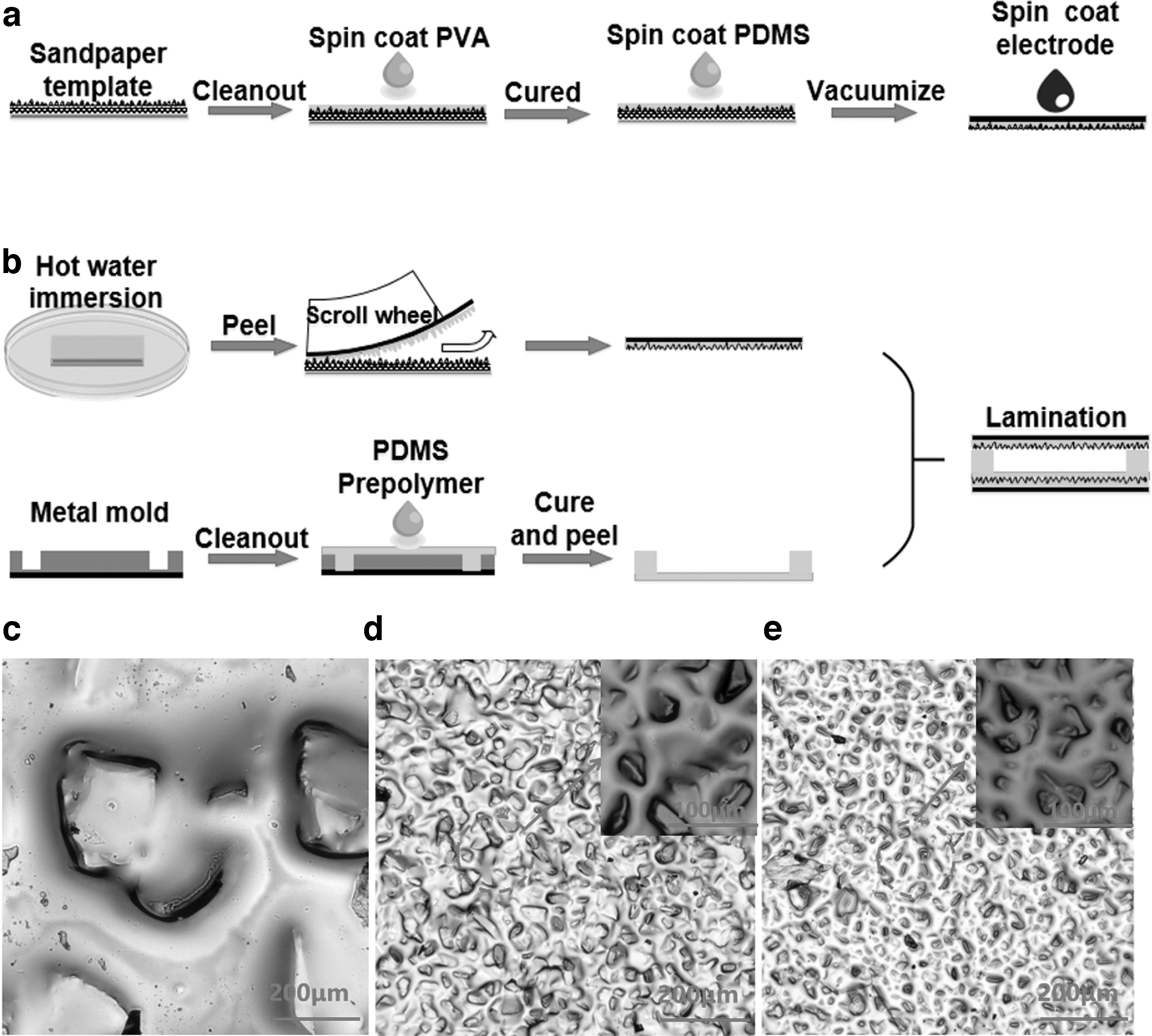
The fabrication process of the fully soft capacitive pressure sensor.
All the surfaces of the layers in the sensor were cleaned by oxygen plasma treatment (90 s) before encapsulation. It is a convenient and feasible method that is usually used for PDMS bonding.6,46 The surfaces activated by oxygen plasma bring good adsorption and binding force. Finally, a layer of 5 μm ultrathin polyurethane tape was used for external packaging, which is featured with the advantages of thin, soft, smooth, waterproof, corrosion resistant, and can be applied in most scenes. The encapsulation layer is the transfer medium between the sensor and the force. In general, the thicker the encapsulation layer, the more energy is lost during the transmission process. So if the package layer is too thick, the sensitivity, detection limit and response/recovery time will be adversely affected. In the tests, no adhesion and separation was observed when the sensor was connected to the human body, robot arm, beakers, wooden blocks, and eggs. Moreover, the proposed sensor in this study shows a distinct scalability. The packaging materials can be optimized according to different actual application scenarios and requirements, such as using materials with better air permeability, or making hydrophilic modification on the surface of the packaging materials. In future study, we will carry out corresponding tests to study the influence of the encapsulation layer on the sensing performances in detail and try to choose more encapsulation material for different applications.
Figure 2c–e shows the optical microscopy images of the microspine fabricated by the 120-grit, 600-grit, and 1000-grit sandpapers, respectively. The surfaces of samples are randomly distributed with a number of irregular microspines with the average sizes of ∼150 μm for 120-grit, 25 μm for 600-grit, and 10 μm for 1000-grit, respectively. The amount of the microspines gradually decrease with the increase of sandpaper grit, thereby providing a smaller contact area and thus having a higher sensitivity at low pressure.
Owing to the special standards and consistency of industrial sandpaper, the repeatability in different batches could satisfy the requirement for large-scale fabrication. In contrast, the roughness standard of sandpaper ensures the statistical uniformity of microspines in the sensor. That means, although the size of every microspine is random, the continuous distribution of the whole layer can be considered to be relatively uniform in a certain area. For example, the average size of the microspines with a roughness of 600 grit is ∼25 μm, suggesting 1.6 × 10⁵ microspines in the area of 1 cm2. As already illustrated (Sensor Characterization section), the devices with same roughness show similar sensing performance, which also proves repeatability to a certain extent.
Sensor Characterization
To demonstrate the benefit of the microspine and pillar structures, the sensors with different hierarchical structures were prepared. The capacitance test system was constructed by a pressure testing machine (ZQ-990A; ZHIQU Precision Instruments) and an inductance capacitance resistance meter (TH2829C; Changzhou Tonghui Electronic Co., Ltd.). Figure 3a–c shows typical real-time responses of the relative capacitance changes for the devices with double, single, and no microspine layers. All the devices show two sensitive behaviors in different pressure range with a sudden change point near 30 Pa.

Here the 600-grit sandpaper was used to fabricate the random microspine layer.
Table 1 summarizes the sensitivity, detection limit, and the response ΔC/C0. As expected, introducing the microspine dramatically improves the pressure sensitivity of the devices. When the imposed pressure is below the pressure of the sudden change point, the sensitivity of the sensor with double microspine layers reaches 2.80 k/Pa, which is increased near 50-fold compared with that of the sensor without microspine layer. The influences of roughness and thickness on the device sensitivity are shown in Figure 3d–g. Within the low-pressure range (0–30 Pa), the sensitivity increases with the decrease of the microspine's size because the small contact area favors the pressure accumulative effect. The sensor prepared by the 1000-grit sandpaper has the maximum sensitivity (2.87 k/Pa) in the low-pressure range. In addition, all the devices show a similar sensitivity in the high-pressure range (0.03–100 kPa).
Sensitivity, Detection Limit, and Response ΔC/C0 of the Sensors with Different Microspine Layers
Low-pressure range: 5–30 Pa; High-pressure range: 0.03–100 kPa.
These results are consistent with the fact that the major sensing mechanism changes from the microspine to the pillar structure with the increase of pressure. This also can be confirmed by the theoretical model as demonstrated in the Equations (2) and (3). Under very low pressure, the volume fraction (fs) of microspine structure increases rapidly with the compression of the microspine structure and the equivalent modulus (Es) also increases rapidly. Because the sensitivity is inversely proportional to Es [Eqs. (1)–(4) in Supplementary Data], there is a descending trend in the device sensitivity. When the microspine is almost completely compressed, the structure loses the function and then the sensitivity exhibits a sudden decline point. After this sudden decline point, the total capacitance of the composite structure is mainly determined by the pillar structure. Due to the large size of the pillar structure, the response trends to maintain invariable, leading to a low sensitivity for the exerted pressure [Eq. (3)]. As already described, to determine the sudden change point, we can only rely on the large number of experiments. In this study, the pressure testing machine was used to apply different pressure to test. The pressure–capacitance response curve is shown in Figure 3. Finally, it was found that the pressure of the sudden decline point of sensitivity was ∼30 Pa.
To evaluate the accuracy and stability of sensitivity, a small pressure of 5 Pa was repeatedly applied 100 times on the surface of the sensor. As shown in Figure 3h, the response signal remains largely the same, revealing a good stability and repeatability. Most of the data are distributed near the middle of the normal distribution diagram, and the deviation on both sides is not more than 0.001. The low mean square deviation (0.00085) indicates a good data convergence without obvious fluctuation (Fig. 3i). From the view of parameter control in the experiments, the measuring accuracy is sufficient to meet the requirement of device reliability. A standard pressure testing machine was used to apply repeated pressure (corresponding to 5 × 10⁻⁴ N). This force can be considered accurate enough because the value is larger than the lowest detection limit of the pressure testing machine (1 × 10⁻⁵ N). Moreover, the response signals were collected by the LCR meter with the detection accuracy of 1 × 10⁻⁴ pF, which is far below the tested capacitance of the sensor (∼1 pF). Actually, compared with other typical studies,50–53 the minimum detectable pressure of 5 Pa is not very low. In our experiments, a smaller pressure was also tested. Because the smaller pressure was difficult to control, the result was not reliable enough and thus not included in the article.
The benefit of microspine is further confirmed by the finite-element analysis (FEA) as shown in Figure 4a. It is obvious that the compression displacement at the small spine's apex is ∼1.5 times that of large spine, revealing that the smaller microspine is more prone to deformity and can provide a better sensitivity. In the fabricated devices, the size of microspine is random, which brings some difficulties for establishment of the FEA model. However, in the low pressure range, the sensor response mainly attributes to the compressive deformation near the microspine apex. Based on this point, the geometry of circular truncated cone was used to simplify the random microspine structure and explain the influencing factors on sensor sensitivity. This simplified model can be accepted because the deformation behavior of the circular truncated cone is very similar to that of the fabricated microspine (both of them have the sharp shape) under low pressure. It is pointed out that the circular truncated cone is possible to ignore some details about small deformation. So this model can only be used to explain the influence of roughness on sensor sensitivity, rather than to design the structure based on it. In a future study, a more complete model will be tried.

The calculated compression displacement by FEA for
Moreover, the experiment results show that the thickness of the microspine layer has little impact on the device sensitivity in the low-pressure range, which is consistent with the compression displacement calculated by FEA (Fig. 4b). On the contrary, in the high-pressure range, the increase of thickness leads to a relative higher sensitivity. This may be the result of differences in initial capacitance. The geometry of the pillar structure was also optimized as provided in Supplementary Figure S1 (Supplementary Data). According to the theoretical prediction and the experimental results obtained by other groups,47,48 the contact area between the dielectric layers is related to the geometry of the pillar structure. The smaller contact area could result in a larger average pressure, which then enhances the sensitivity. In this study, the performances of our sensors with square and circular pillar structures were compared in the experiment (Supplementary Fig. S1) and the FEA (Supplementary Fig. S2). The result of the FEA indicates that the compression displacement of the circular pillar structure is higher than that of the square pillar structure with the ratio of 4:3. It is obvious that the performance of sensors with circular pillar structure is better than that of sensors with square pillar structure.
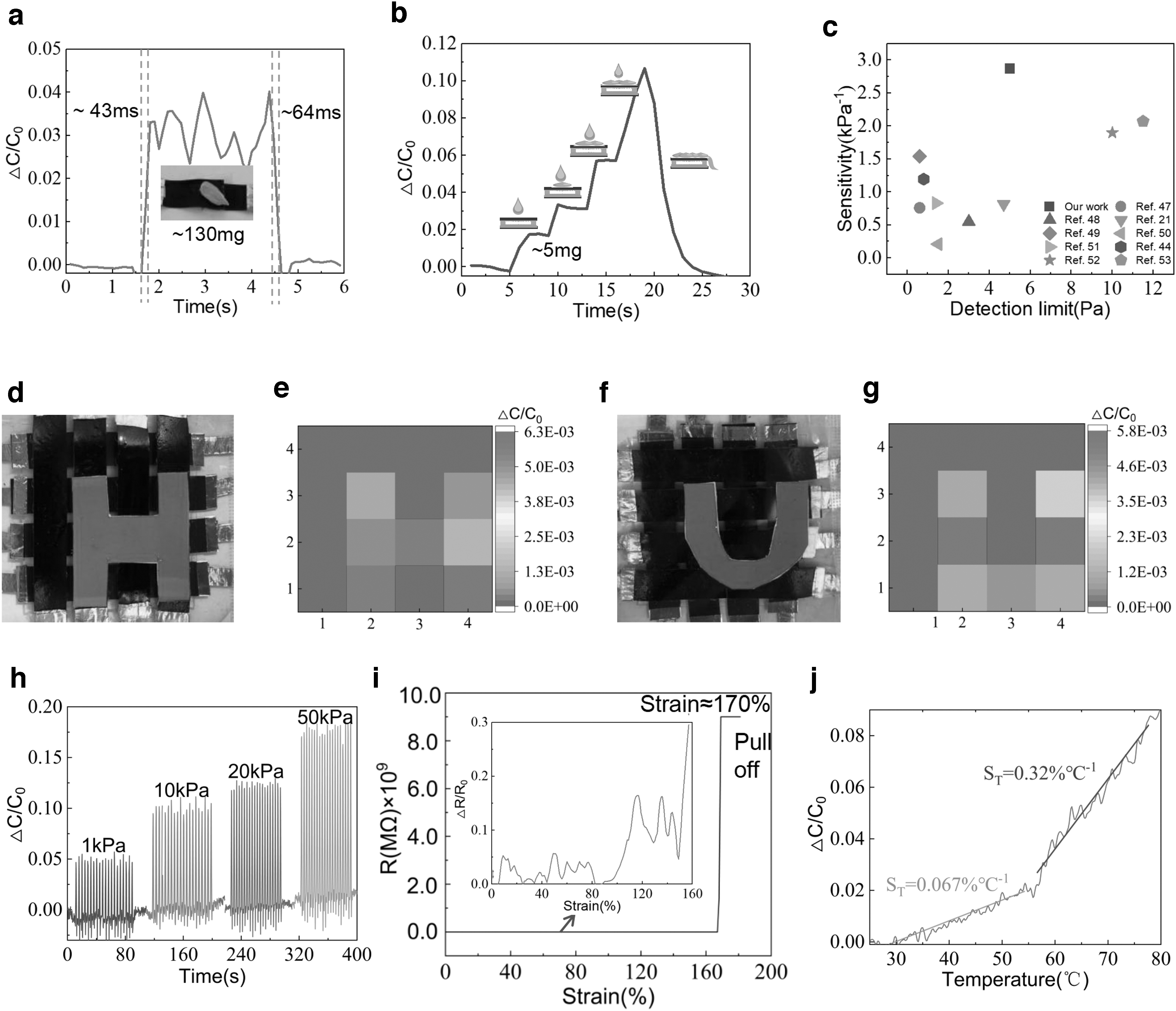
The response and recover times were estimated by loading/unloading a small melon seed on the surface of the sensor (∼130 mg/13 Pa; Fig. 5a). The tiny pressure yields a clear capacitance change with the quick response/recovery times (43/64 ms) compared with human skin (∼50 ms). Furthermore, the limit of detection is investigated with the help of water drops (∼50 mg) that apply a small pressure of ∼5 Pa. As shown in Figure 5b, visible and distinguishable responses can be observed when continuously adding water droplets. After four drops, the surface of the sensor is no longer able to hold the water, and the water drops flow away from the device area, resulting in a sharp fall in the capacitance response. Table 2 and Figure 5c list the comparison of the information on the materials, structures, and the sensing performances from the recent published capacitive sensors. Benefited from the hierarchical structures consisted of microspine and pillar structure, our sensor exhibits a high sensitivity, low detection limit, and broad pressure range.
Information on Materials, Structures, and Sensing Performances from the Recent Published Capacitive Sensors
AgNWs, Ag nanowires; ITO, indium tin oxide; MWCNTs, multiwall carbon nanotubes; PDMS, polydimethylsiloxane; PET, polyethyleneterephthalate; PS, polystyrene; Al, aluminum.
A 4 × 4 sensor array was prepared using the proposed devices and tested by placing the “H” type and “U” type plastic patterns with masses of 1.9 and 1.36 g, respectively. As shown in Figure 5d–g, the capacitance of the units below the plastic pattern changes significantly, while other units still keep their initial state. The geometrical shape of the objects can be distinctly judged by the spatial pressure distribution. Figure 5 h shows the cyclic capacitance responses of the sensor to four pressure levels. The repeatability of the sensor is evaluated by applying/releasing 20 pressure repetition cycles in sequence. The response rises significantly with the increased external pressures and there is no obvious deviation or delay under the same pressure. The patterns of every responsive cycle under different pressure levels are highly identical, demonstrating the excellent repeatability in a broad pressure range. Moreover, the sensor was installed on the pressure testing machine, and 1000 cycles were carried out under the pressure of 100 Pa. As shown in Supplementary Figure S4a (Supplementary Data), the durability of our sensor is pretty good and the enlarged insets indicate that the profile of the relative capacitance change is considerably uniform and no obvious fatigue can be witnessed. Supplementary Figure S4b (Supplementary Data) displays the data distribution of the 1000 groups. The result illustrates that most of the data are mainly distributed near the center of the normal distribution with a low mean square deviation (0.00485), which proves the long-term stability and robustness of the device.
As a capacitive sensor, the stability of electrode is an important factor affecting the performance. Figure 5i shows the resistance of the MWCNT–PDMS electrode used in our design under the strain of 0–180%. The maximum variation in resistance is only 5% when the strain is <100%. Even under the stretching strain of 150%, the variation in resistance is still <20%. The temperature stability of the sensor is depicted in Figure 5j. When the sensor is loaded with a weight of 1 g, the sensor shows low temperature coefficients of 0.067%/°C in range of 25–55°C and 0.32%/°C in the range of 55–80°C, respectively.
Application in the Detection of Various Movements of the Human Body
Some typical applications for monitoring human motions, physiological activities, and mechanical grabbing of robots are demonstrated here. Since all the parts in the proposed sensor, including dielectric layer and electrode layers, are made by PDMS, the soft capacitive pressure sensor has the ability to perceive both press and bending force. The sensor can return to the initial state quickly under stretch, bend, and twist condition without causing the intrinsic capacitance to change. As shown in Figure 6a and b, the sensors were attached on the surfaces of the index finger and wrist to monitor the different bending states. Based on the fully flexible structure, the sensors contacted conformally with the skin and followed the skin extension closely, allowing good responses to both the subtle bending of fingers and the large-scale flexing in the wrist. More significantly, five identical pressure sensors were implemented and, respectively, attached to the different fingers of a rubber glove to construct a “smart glove” (Fig. 6c). The devices suffered pressure and produced a response pattern that can be used to recognize the various gestures in real time. As shown in Figure 6d, when the hand grasped the different beakers (empty/with 100 mL water/with 200 mL water), the states were distinguished by the combination of responses of the five sensors. Figure 6e–i shows the responses to the tiny pressures produced from human physiological activities. The signals induced by different expressions, including smiling, speaking different words, and swallowing, are stable, repeatable, and distinctive. We noted that the twice responses to speaking the word “S” showed similar amplitude, width, and waveform. These results suggest the potential applications of our sensor in prosthetics, humanoid robotics, and speech recognition.
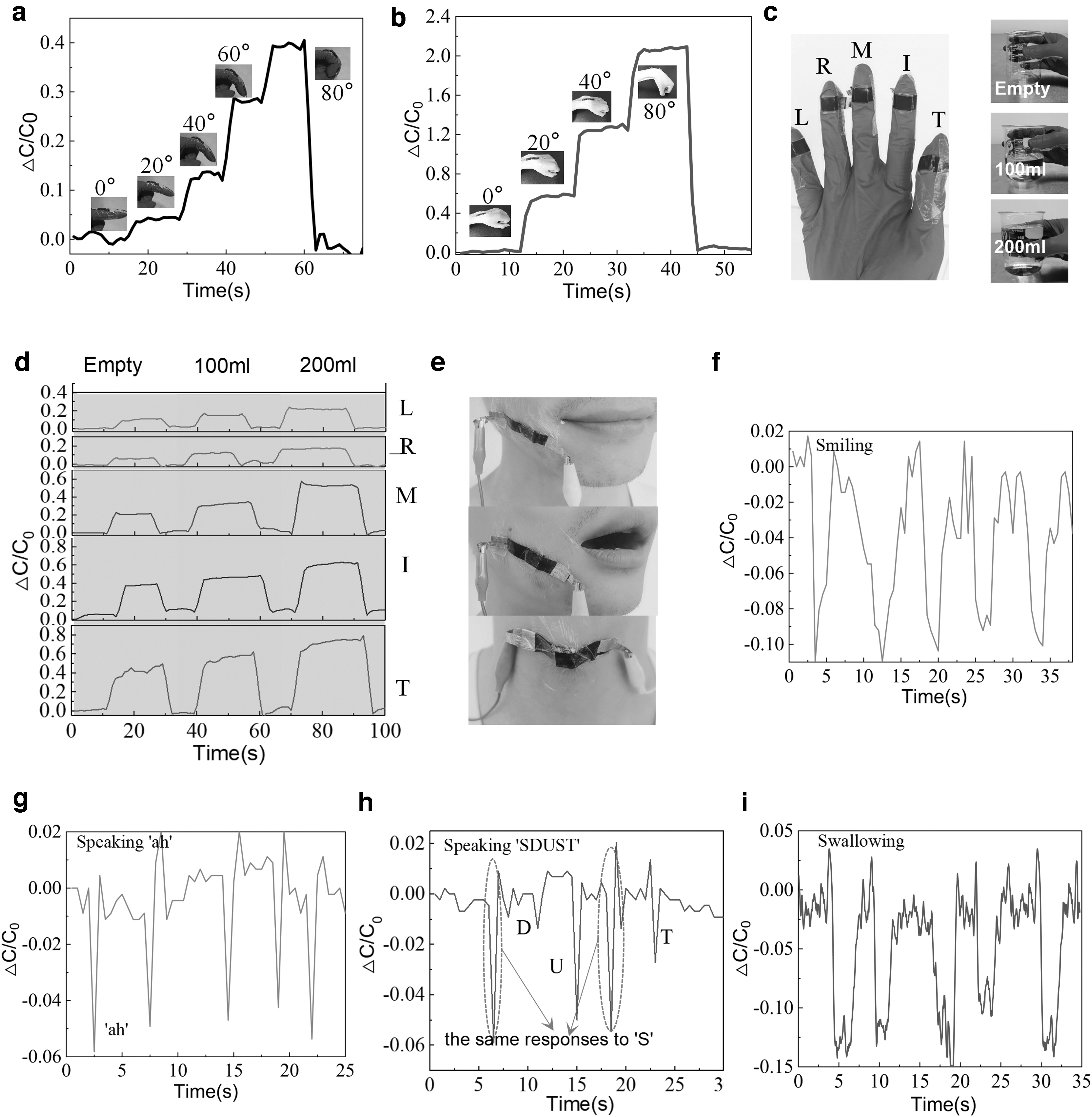
Supplementary Figure S3 (Supplementary Data) illustrates the capacitance response of the sensor under bending, twisting, and in-plane stretch (10–30%), respectively. When the sensor was stretched for 30% without vertical surface pressure, the capacitance response was only 3%. By contrast, finger bending and facial movement produced the capacitance responses up to 10–40% as shown in Figure 6a and e, although the stretches of the sensor were much <30%. The results demonstrate that the in-plane stretch has no significant impact on the sensor sensitivity due to the supporting effect of the pillar structure. It is believed that the main reason for the capacitance response is the vertical pressure on the sensor surface caused by the joint bending and facial muscle activity during human motion.
Illustrative Applications for Mechanical Hands and Soft Robots
To demonstrate the feasibility for the detection of high-precision clamping in robots, the pressure sensors were fixed on a robot arm and a soft claw to monitor the pressure during the grasping and releasing processes (Fig. 7a, b). A multichannel test system was designed to measure and store the capacitance signals in real time. In this study, the claw was driven by a motor with the power of 36 W for robot arm and 64 W for soft claw, respectively.

Figure 7c shows the capacitance responses when the robot arm clamped a potato chip, a sponge, and a wooden block. The sensors produce good responses to the clamping force exerted on the robot arm, even for the very light potato chip. Obviously, the heavy weight and the increased friction result in a high pressure and a large capacitance response. Another important issue in industrial robots is the instantaneous detection of the touching between machine and human body. Particularly in the human–machine collaboration environment, the robot should detect the touching immediately and quickly make a stop or away command to avoid causing casualties or property damage. In this study, the sensor was used to monitor the motion perturbation during the clamping processes (Fig. 7d). A sharp and immediate capacitance change was seen at the moments when the sponge touched the desktop, suggesting an accepted touching detectability for the human–machine collaboration system.
More importantly, the objects with different moduli can be distinguished using our devices. For this purpose, a rigid wooden block and a soft steamed bread with the same weight were clamped by the robot arm and the capacitance responses were compared in Figure 7e (Supplementary Video S1). According to Newton's law, the motor power equals the product of its output torque and rotational speed. When the sensor contacts the object, the capacitance change of the sensor attached on the claw reflects the output torque of the motor through the interaction force between the claw and object. The gripping rate of the mechanical claw is determined by the rotational speed. First, as shown in Figure 7e, the gradient of the response–time curve is related to the elastic modulus of the object during the gripping process of the mechanical claw. The following reasons can explain this phenomenon. For the rigid objects that are hard to deform (such as wooden block and fresh egg), the gripping speed of the claw (corresponding to the motor rotational speed) drops rapidly because of the high moduli of objects. The accompanied rise of motor torque and the force between the claw and object result in a sharp increasing capacitance response with a large slope. In contrast, in the case of steamed bread and cooked egg, the objects with low moduli could deform gradually when the force applies on it so that the gripping rate of claw decreases slowly, producing a slow trend in the contact force change and the capacitance change of sensor.
Regarding the maximum responses of different objects (the time of 10–15 s in Fig. 7e), there may be many factors that account for this result, but the pillar structure of sensor is the most typical ones. During the gripping process of the mechanical claw, the pillars with a certain interval are the main supporting points. When the claw movement reaches the limit (corresponding to the maximum deformation of objects), the motor works as the full power state. Although the total force applied on the sensor surface is same for the objects with different elastic moduli, there exists different deforming distribution on the sensor surface as shown in Figure 7f.
The contact of rigid object produces a uniform deformation in the upper surface of the sensor. With the compression of pillars (Δd), the distance between the two electrodes decreases and thus the capacitance response increases. However, when the soft objects with low moduli contact with the sensor closely, an additional deformation (Δd′) occurred between the pillars under the effect of squeezing force. This makes the upper surface of the sensor sink inward and the electrode further close, resulting in more capacitance change (corresponding to the distance change Δd+Δd′) compared with that of rigid objects. It can be expected that the maximum capacitance response of the sensor is related to the distance of the pillars and the shape of the object.
The proposed sensor features the fully deformable and resilient structure that ensures a snug fit to the soft or cambered actuators. Based on this point, an array consisting of three sensing units (Fig. 7b) was integrated into a soft claw made of acrylonitrile butadiene styrene plastic. Figure 7g and h and Supplementary Video S2 show the capacitance responses when the fresh/cooked eggs and a wood block were grasped by the soft claw, respectively. Thanks to the conformal and close contact between the claw and objects, the deformation differences derived from the profile and hardness are recognized clearly by combining these response curves. These results indicate the sensor array is able to provide important feedback information for the robots control system especially for the task of grasping fragile and irregularity objects.
Conclusions
In conclusion, inspired by the hierarchical structure of human epidermal tissue, we have designed a fully soft capacitive pressure sensor with bionic spine–pillar microstructure by combining two sandpaper-molded microspine layers and a millimeter-scale pillar array. This structure allows a localized and high stress concentration at the microspine's apexes in contact with the pillar cells, enlarging the external stimuli and thus enhancing the pressure perception. The pillar array is responsible for detecting the large pressure after the microscale spines are completely compressed. Therefore, the sensor presents several conspicuous features, including an ultra-high sensitivity, an ultra-low detection limit, a fast response/recover time, and excellent stability. For proof of concept, our fully soft pressure sensor has been demonstrated for detecting tiny pressures produced from human physiological activities, such as smiling, speaking different words, and swallowing. More importantly, it has been proved that the proposed sensor can be integrated into mechanical and soft robots as a tactile perception unit to recognize the shape and hardness of objects and provide real-time tactile feedback information for the robots control system. It is believed that the design method of combining the microspines and the pillar array will be of significance for the development of soft robots on safe human–robot interaction, surgical robots, and human–machine integration systems.
Footnotes
Author Disclosure Statement
No competing financial interests exist.
Funding Information
This study was supported by National Natural Science Foundation of China (Grant Nos. 61574086, 61871281), Shandong University Youth Innovation Supporting Program (Grant No. 2019KJN020), the Tai'shan Scholar Engineering Construction Fund of Shandong Province of China, Key Laboratory for Robot and Intelligent Technology of Shandong Province (Grant No. KLRIT2018003).
References
Supplementary Material
Please find the following supplemental material available below.
For Open Access articles published under a Creative Commons License, all supplemental material carries the same license as the article it is associated with.
For non-Open Access articles published, all supplemental material carries a non-exclusive license, and permission requests for re-use of supplemental material or any part of supplemental material shall be sent directly to the copyright owner as specified in the copyright notice associated with the article.