
Abstract
We present a multi-material three-dimensional-printed snakeskin with orthotropic friction anisotropy, which permits undulatory slithering of a soft snake robot on rough surfaces. Such a snakeskin is composed of a soft skin base and embedded rigid scales attached to the robot's ventral surface. The bioinspired designs of scale shapes and arrangements lead effectively to various types of anisotropic friction, and provide means of switching robot's locomotion direction to be either the same as or opposite to the propagation direction of the traveling-wave undulation. Furthermore, steering of locomotion can be achieved by applying additional pressure bias in one air path to break symmetry of body deformation. We also successfully demonstrate the snake robot's mobility on various outdoor rough substrates, including concrete surfaces and a grass lawn, as well as pipes of different dimensions and materials, for potential field applications.
Introduction
Bioinspired structures and actuators are utilized extensively to achieve various functions for robots, such as grasping and locomotion.1–3 Animals have been sources of inspiration for a myriad of mechanism designs: biomimetic shark skins, 4 fibrillar gecko pad adhesive interfaces, 5 robotic water striders, 6 and legged and underwater robots.7,8 In particular, the softness of robots inspired by the soft structures of animals, makes such robots more robust to environmental challenges. 9 Numerous soft robots have been developed for different applications, such as inspection, human–machine interaction, and medical surgeries, 10 inspiring ideas for designing more robust, human-friendly robotic solutions for daily tasks.
Snake robots have been developed to achieve simple but robust locomotion mimicking limbless animals.11–13 They are of particular interest in several scenarios, like minimally invasive surgery and rescue tasks, because of their compact structure and flexibility, enabling them to adapt to different environments.14,15 As one common and efficient locomotion method, serpentine motion or slithering of snakes relies on traveling-wave deformation of their bodies and the orthotropic friction anisotropy (distinct frictional properties in longitudinal and lateral directions) generated by their skins. 16 During the undulation, different parts of the snake have different velocity directions, and the angles formed between local velocity directions and local body orientations are different.
The friction on the ventral surface thus has a varying magnitude along the body owing to the friction anisotropy, with a resulting integral of the friction generating the propulsion for the serpentine locomotion. 16 This locomotion method allows bioinspired robots to use slim structures to advance in complex environments and was initially achieved by rigid-link snake robots, the deformation of which was activated by motors.17,18 Recently, several soft snake robots were created by using soft bending actuators, which enhances their flexibility.19,20 To generate friction anisotropy, passive wheels were widely used in these robots, with rolling and sliding frictions in the orthogonal directions. However, the use of passive wheels compromises the adaptability of soft robots and limits their utility in field applications. Therefore, developing a compact soft snakeskin with orthotropic friction anisotropy is of significant interest.
There have been various studies on incorporating functional surfaces into mobile robots and utilizing special textures to meet the needs of versatile applications. 21 Kirigami skins, cylindric scale arrays, and barbed and sawtooth-like structures were proposed to drive soft crawling robots and provided friction anisotropies.22–30 Movable skins were also implemented to achieve agile locomotion for snake robots at the cost of complex mechanisms.31,32 In particular, notable examples of functional structures for friction anisotropy include hook-like structures, 33 snakeskin-inspired clay-structure interfaces, 34 and spiky skin structures. 35 There have also been studies focusing on friction attributes of surfaces and skins.36,37 The complex friction anisotropies of different real snakeskins were analyzed,38,39 and it was shown that the transverse friction of a snake is higher than the longitudinal frictions on rough surfaces. 16 Several bioinspired surfaces and sawtooth-like structures were designed and tested by emulating the microstructure of snakeskins and other rough surfaces.40–43
In this study, inspired by the snake scales on soft skin base and by the structures with friction anisotropies,42,43 we present a novel type of snakeskin with orthotropic friction anisotropy, which enables the serpentine locomotion of a pneumatic soft snake robot on rough surfaces when the robot's traveling-wave deformation is activated. Compared with other common barbed or sawtooth-like structures25–30 which generate friction anisotropies in opposite directions, the combination of the soft skin and rigid scales in the proposed design achieved orthotropic friction anisotropy similar to real snakeskins. The softness of the skin base provided robustness and compliance to soft robots while the rigidity of the scales improved the friction anisotropy and wear resistance.
In addition, compared with reported passive wheels for soft snake robots,17,18 the proposed snakeskin was more compact and adaptable to versatile environments. The proposed snakeskin consisted of a soft base skin and embedded rigid scales (Fig. 1E). The rigid scales on skins, resembling the snake scales, provided friction anisotropy, whereas the soft base skin provided the flexibility to cling to the deformable robot body (Fig. 1F). A modular pneumatic soft snake robot 11 acted as the robot body that could generate traveling-wave deformations, to which the snakeskin was adhered by using silicone glue (Fig. 1A). The soft snake robot was composed of six soft pneumatic bending actuators and each of them contained four separated air chambers (Fig. 1D). There were four air paths in the robot and each of them was connected to one air chamber in each bending actuator.
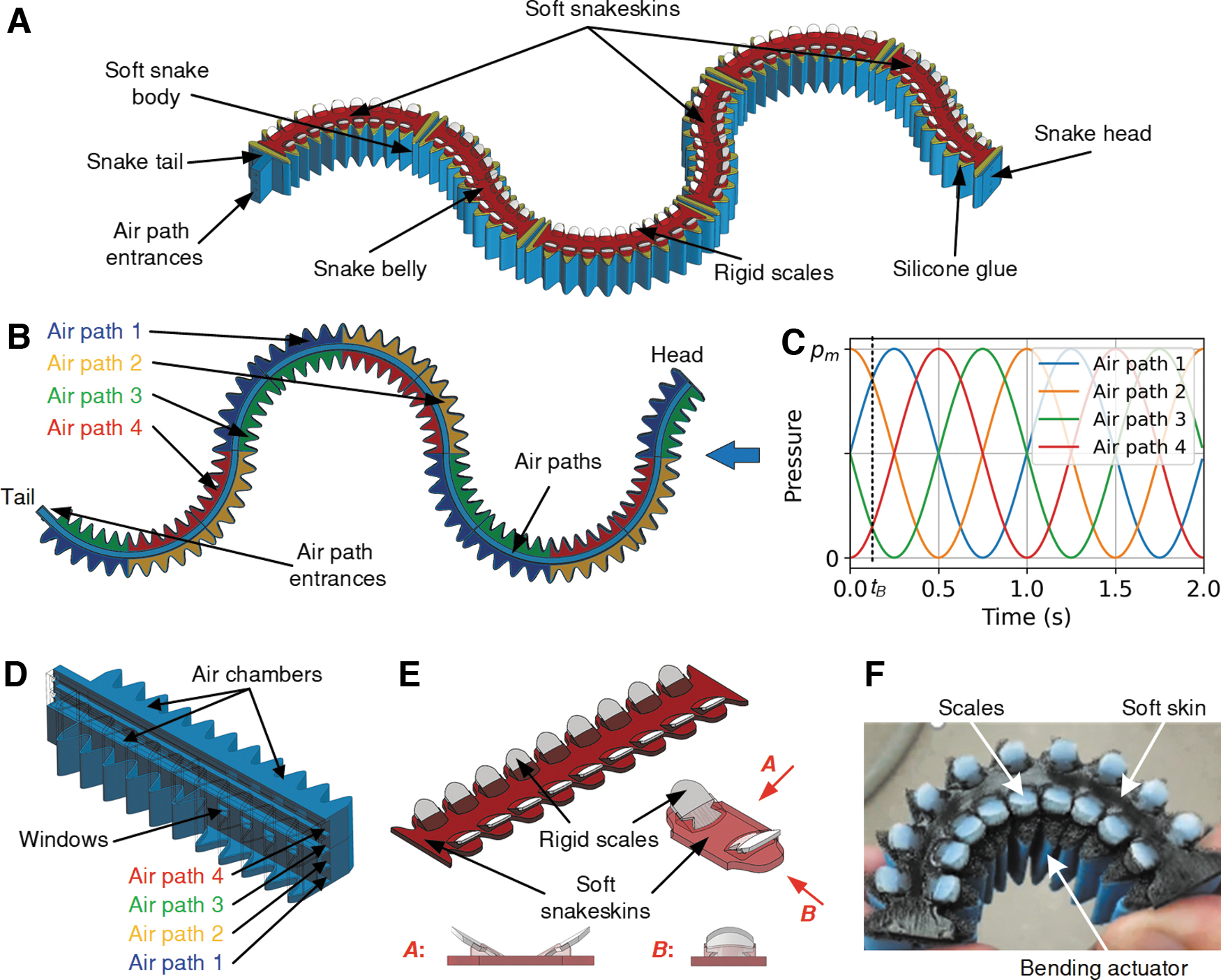
Bioinspired soft snakeskin and the robot.
The linkages between the air paths and the chambers in actuators were carefully designed to generate wave-like bending deformation (Fig. 1B). Then, the traveling-wave deformation of the robot could be achieved by using the time-varying sinusoidal pressures with phase differences in the four air paths (Fig. 1C) that were generated by a pressure control board (Section S4 in Supplementary Data). The traveling-wave propagation direction could be controlled by switching between phase-lagged and phase-advanced pressures. On the rough substrates, once the traveling-wave deformation of the snake robot with snakeskins was generated, the anisotropic friction between the substrates and the skins would propel the robot to achieve serpentine locomotion like real snakes.
Materials and Methods
The soft snake robot with snakeskins comprised of two parts: soft robot body and snakeskin, which were fabricated separately and then assembled together. The soft snake robot body was modularly fabricated by a three-dimensional (3D) printer (QIDI TECH I) using a soft filament (Filaflex 82A, Recreus). Then, the modular segments were connected using soft tubing and were adhered together using flexible glue (Sikaflex, Sika). The snakeskins were fabricated by a 3D printer (Objet Connex 350) using a rigid material (Objet Vero white) and a soft material (Objet Tango Black) for scales and skin bases, respectively. After both parts were produced, a silicone material (Ecoflex 00-30, Smooth-On) was utilized as the glue to combine the robot body and the snakeskins. More details on the robot's fabrication, experimental setups, experimental data processing methods, and pneumatic actuation system is given in Supplementary Data.
Results
Orthotropic friction anisotropy of the scales on the snakeskins
The robotic snakeskin proposed in this study adopted a hybrid structure: a soft skin base with rigid embedded scales. Three different shapes were proposed for the outer edge of the scales: triangular, circular, and trapezoidal (Fig. 2A). Each type of scale had width w = 5 mm, length l = 6 mm, and an opening angle α = 30 degrees between the skin base surface and scale surface. The presence of the opening angle allowed overlapping scales to cover the entire snakeskin and improved the flexibility of the skin in the vertical direction for uneven substrates. Furthermore, to secure the connection between the rigid scales and the soft base, an anchor structure was used at the inner end of the scale that was implanted in the soft skin base (Fig. 2A).

Friction anisotropy of scales of different shapes on various substrates.
Experiments were conducted to investigate the friction properties between the scales and different rough surfaces and examine the feasibility of using the proposed scales to generate orthotropic friction anisotropy. A cotton canvas layer and a paper layer, respectively, were used as the substrate surfaces for these experiments. Experimental setups and data processing methods for the results are elaborated in Supplementary Data (Section S2). In the experiments, by choosing different angles θ between the scale direction and the moving direction of the scale samples pulled by a linear stage, the friction forces fθ between scales and substrates were measured when the moving directions of the scales were fixed (Fig. 2B). In particular, two different moving directions (along the fibers, which is smooth, vs. transverse to the fibers, which is rough) on the canvas surface were selected because of the pronounced roughness anisotropy of the canvas.
After the friction forces fθ between the scales and substrates were measured, the coefficients of friction μθ of the scales on the corresponding substrates were calculated by:
where
where
In the experiment, it was shown that the proposed bioinspired scales were able to generate both orthotropic and reversed friction anisotropies on rough surfaces (Fig. 2C–F). Most distributions of μθ for scales on rough substrates exhibited clear orthotropic anisotropy characterized by elliptical shapes, generally showing that μθ decreased with the angle θ between 0 and 90 degrees and increased with the angle θ between 90 degrees and 180 degrees. Also, the distributions showed that μθ with θ between 180 and 360 degrees was symmetric to that between 0 and 180 degrees, which resulted from the geometry symmetry of the proposed snake scales.
In particular, μθ of the triangular scales remained almost the same when θ was between 90 and 180 degrees, which might be owing to the shape of the contact areas (could be assumed as an ellipse) between the scales and the rough substrates. The eccentricity of the ellipse contact area between the triangular scale and substrates was much smaller than that of the circular or trapezoid scale because of their edge shape. Thus, this more isotropic contact area of the triangular scale resulted in its almost constant μθ with θ between 90 and 180 degrees, where the mechanical interlocking effect was not dominating.
The friction anisotropies between the scales and each substrate were also compared (Fig. 2D–F). On all substrates, the orthotropic friction anisotropy of the scale increased when the shape changed from triangular to circular to trapezoidal, while the reversed friction anisotropy of the scale increased when the shape changed from circular to trapezoidal to triangular. It needs to be mentioned that the triangular scale exhibited the highest reversed friction anisotropy on all substrates, which might be attributed to a stronger mechanical interlocking effect brought by its sharper tip compared with edges of other scales.
Baseline locomotion of snake robot with isotropic skins
The previous literatures 16 showed friction anisotropy was necessary for snakes to achieve efficient serpentine locomotion. A foam layer (Super-Cushioning Polyurethane Foam Sheet, McMaster-Carr) was thus used as an isotropic snakeskin to provide a baseline for examining the serpentine locomotion of the snake robot. The foam layer was much softer than the robot body and was adhered to the ventral surface of the robot by using a thin acrylic adhesive layer (Fig. 3A). In baseline experiments, the aforementioned paper and canvas surfaces were used, and pressures (Fig. 1C) with a period T of 1 s were used to generate the robot's traveling-wave deformation. The coefficient of friction between the foam and paper substrate and that between the foam and canvas substrate were measured as 1.104 and 1.417, respectively, by using the same method as adopted for the measurement of friction properties for the proposed scales. The locomotion experimental setup and the data processing methods for the results are elaborated in Supplementary Data (Section S3).

Snake robot with isotropic ventral surfaces and the baseline experiments.
In the baseline locomotion experiments, it was shown that the traveling-wave deformation of the robot was successfully activated by the pressure inputs, and the snake robot moved slowly because of the lack of friction anisotropy (Fig. 3B, C). It was also shown that the robot's maximum curvature κm, which was correlated with the traveling-wave's amplitude, increased with the pressure amplitude pm of the pressure inputs (Fig. 3E). In addition, κm on the canvas was smaller than that on the paper when the same pm was used; this could be attributed to the larger resistance between the foam skin and the canvas substrate, which showed that the interactions between the robot and substrates could influence the deformation of the robot itself. Moreover, the experimental results showed that the robot's speed v increased with pm, with a maximum speed of 5.67 mm/s when pm was 172 kPa (25 psi) and the substrate was the paper (Fig. 3F). Note that the forward movement could be partially attributed to the propelling effect of the pneumatic input, which transferred some momentum to the robot.
Serpentine locomotion of the snake robot with snakeskins
Following the experiments with the isotropic foam skin, the proposed snakeskins were implemented on the snake robot to generate serpentine locomotion, where the substrates, pressure inputs (except the phase relations of the pressures), experimental setups, and data processing methods were the same as those used in the baseline experiments. In particular, we could tune the phase relation of the pressure inputs (i.e., phase-lag or phase-lead) to generate traveling-wave deformation that propagates either forward or backward along the robot's body. Note that the orthotropic friction anisotropy of the snakeskin on substrates, a key factor in generating serpentine locomotion, was determined by both the shape of the scales (Fig. 2) and the arrangement direction of the scales on the skin base (Fig. 4A–C). By using the μθ distributions of the scales and their specific arrangements on the soft base, the snakeskin's coefficient of friction μsθ could be calculated by taking the mean of μθ of every scale on that snakeskin in the θ direction (Section S5 in Supplementary Data).

Serpentine locomotion of the snake robot with differently arranged snakeskins with circular scales.
To examine the locomotion performance of the robot with various snakeskins, three skins with different scale arrangements were tested first, where the circular scales, which resemble real snake scales the most, were adopted. The reversed scale arrangement (RA), collateral scale arrangement (CA), and orthogonal scale arrangement (OA) for the snakeskins were designed and used (Fig. 4A–C, respectively). All three arrangements had two rows of scales and adopted a mirror symmetry. The orientation difference between the scales of the two rows was 180 degrees, 0 degree, and 90 degrees for RA, CA, and OA, respectively. The μsθ distributions of different snakeskins on the paper substrate were presented beneath the skin designs (Fig. 4A–C). It was shown that the snakeskin with RA and CA had orthotropic anisotropies, where the largest μsθ was on 90 and 180 degrees direction, respectively; but for the snakeskin with OA, the distribution of μsθ was nearly isotropic.
In the locomotion experiments, it was shown that the snakeskins with RA and CA both successfully generated the serpentine locomotion of the robot on the substrates, whereas the snakeskin with OA could not drive the robot efficiently (Fig. 4D–I). It was also shown that the direction of the robot's serpentine locomotion was opposite to (the same as, respectively) the traveling-wave propagation direction, when the skin with RA (CA, respectively) was adopted. This reverse of locomotion direction with respect to the traveling-wave direction was attributed to the difference of the orthotropic anisotropy in the two snakeskins, of which the directions of the largest μsθ were orthogonal to each other. As an intermediate design between the snakeskins with RA and CA, the snakeskin with OA generated inefficient locomotion, neither moving forward nor backward with respect to the traveling-wave direction. It was also noticed that the robot had a slow lateral sway during the locomotion, which might be attributed to the imperfection in the 3D printing of the soft snake robot.
Quantitative results of the serpentine locomotion of the robot with different circular scale arrangements are further presented (Fig. 5A–F). It was shown that both the locomotion speed v and the curvature κm increased with pm, and the maximum speed reached ∼31 mm/s when the snakeskin with RA was used on the canvas, with pm of 172 kPa (25 psi). It was also noticed that κm of the robot with RA was smaller than those with CA and OA, which was attributed to the stronger lateral resistance provided by the snakeskin with RA. For the robot with RA and CA (Fig. 5D, E), it was shown that both the speed v and its increasing rate (with respect to pm) increased with pm within the experiment range; and that the speed v was larger on the canvas than that on the paper when the same snakeskin and pm were used, which could be attributed to the higher orthotropic friction anisotropy between the skins and the canvas. In addition, the robot with skins with OA was much slower than the robot with other scale arrangements (Fig. 5F), which might be attributed to the much weaker friction anisotropy of this type of snakeskin.

Quantitative locomotion results of the robot with differently arranged snakeskins with circular scales.
To further examine the impact of the scale shape, we compared the robot's locomotion performance when using the triangular-, circular- and trapezoidal-shaped scales with either RA or CA on the snakeskins (Fig. 6C, F). The orthotropic friction anisotropies of snakeskins

Serpentine locomotion results of the robot with reversely and collaterally arranged scales of different shapes.
In the experiments for different scale shapes, it was shown that the robot's speed v, as well as its increasing rate, increased with pm given the same snakeskin and substrate. Among all the snakeskin designs, the one with RA and trapezoidal scales had the best locomotion performance, where the speed v increased from 0 to 37 mm/s when pm increased from 0 to 172 kPa (25 psi). Among the snakeskins with RA, the skin with trapezoidal scales generated the fastest serpentine locomotion for given pm and substrate, followed by the skin with circular scales, and then by the skin with triangular scales (Fig. 6D, E), showing consistency with their
Steering locomotion of the snake robot with snakeskins
The steering capability of the soft snake robot with snakeskins was further studied following the verification of the effectiveness of the proposed snakeskins in generating serpentine locomotion. In the steering experiments, snakeskins with RA and CA and circular scales were used. To generate turning, single-channel biased sinusoidal pressure inputs (Fig. 7B, C) with pm of 138 kPa (20 psi) and T of 1 s were used, replacing the unbiased pressure inputs (Fig. 7A) used in the previous locomotion tests. As a result, the induced asymmetric bending deformation led to a laterally unbalanced traveling wave (Fig. 7E, F), resulting in a moment for the turning of the robot. The additional biased pressure pbias was applied to the second air path and the fourth air path to generate left turn and right turn, respectively. Their turning directions were opposite because the air chambers linked to the second and fourth air paths had laterally mirror-symmetric positions in the robot body (Fig. 1B).
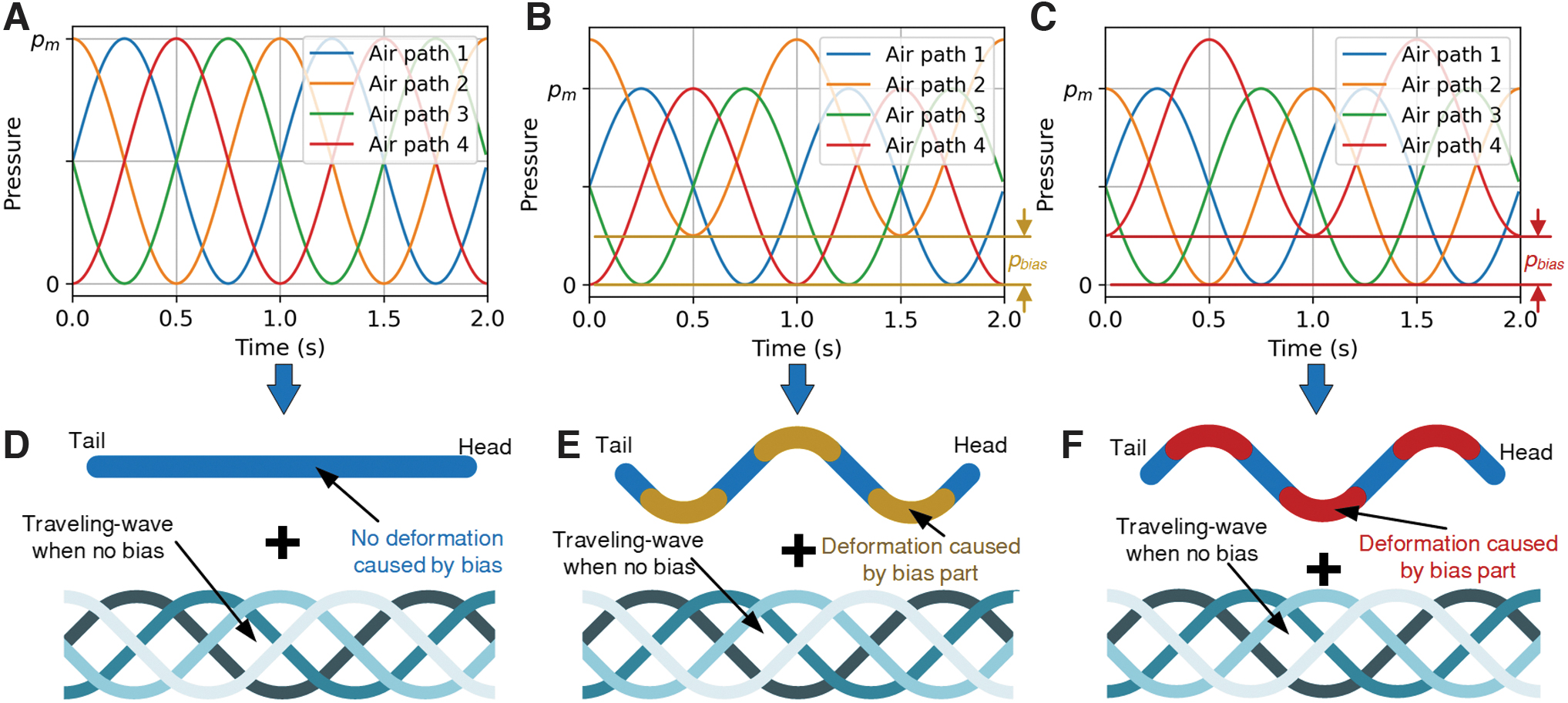
Pressure inputs and deformation modes for the steering of the snake robot.
The trajectories of the center of mass of the robot with biased pressure inputs are given in Figure 8A–D, for snakeskins with RA and CA, on the canvas and the paper, respectively. The angular velocities ω of the robot in all these cases are given in Figure 8E and F, where positive (negative, respectively) ω denotes turning right (left, respectively).
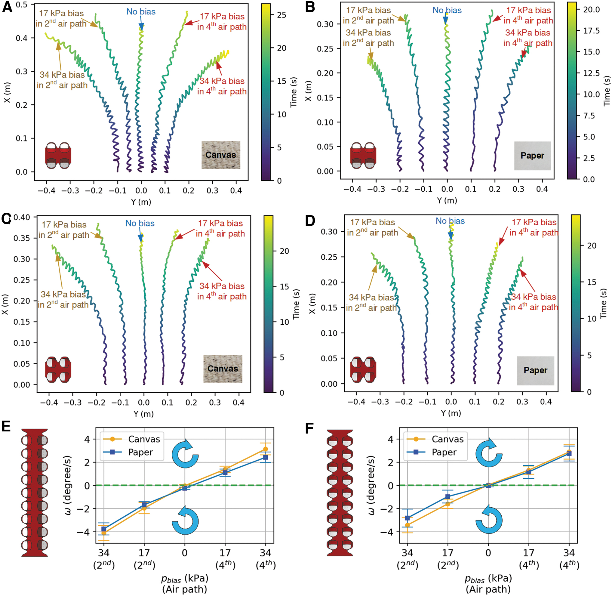
Trajectory of the center of mass of the snake robot in the steering experiments, and the angular velocities of the robot in different settings.
In the experiments, it was shown that the robot turned left and right on both substrates when the pbias was applied to the second air path and fourth air path, respectively, and the magnitude of ω increased with pbias in the second or fourth air path in the experiment range. The trajectory symmetry of the robot with the same pbias in the second and fourth air path was observed, and it was also shown that the snake robot went almost straight when pbias was 0. However, it was noticed that the left turning was almost always faster than the right turning given the same pbias and substrate, which might be attributed to the imperfection in the 3D printing and the assembly process. It was also observed that the robot on the canvas generally turned faster than that on the paper given the same skin and pbias. The robot with RA generally turned faster than that with CA given the same substrate and pbias, with the exception when the paper substrate and the bias pressure pbias in the fourth air path were applied.
Outdoor and in-pipe tests of the soft snake robot
The soft snake robot with the proposed snakeskins was also tested in three outdoor environments, including two concrete surfaces with different roughness levels and a grass lawn. Pressure inputs with pm of 172 kPa (25 psi) and pbias of 0 kPa were used to generate straight serpentine locomotion and the robot's speed was estimated from the recorded videos (Supplementary Video S1). The snakeskins with RA and trapezoidal scales (Fig. 9A–C) and the skins with CA and trapezoidal scales (Fig. 9D–F) were implemented in the outdoor tests. Furthermore, three different pipes were used to test the robot's locomotion ability in constrained environments, where the skins with CA and trapezoidal scales (Fig. 9G–I) were implemented and pressure inputs with pm of 138 kPa (20 psi) and pbias of 0 kPa were used.

Locomotion of the snake robot on different outdoor substrates and in pipes.
The experiments showed that the proposed snakeskin could help the robot adapt to various surfaces and achieve serpentine locomotion. Consistent with the experiments with the canvas and paper surfaces, the robot's locomotion directions on both concrete surfaces were opposite to (the same as, respectively) the traveling-wave propagation directions, when using snakeskins with RA (CA, respectively). The locomotion speed reached ∼21 and 23 mm/s on the smoother and rougher concrete surfaces, respectively, for skins with RA, and reached ∼15 and 18 mm/s on the two concrete surfaces, respectively, for skins with CA. Moreover, we found that in the grass, the locomotion direction was always the same as the traveling-wave propagation.
The speed of the robot with RA was ∼2 mm/s, slower than the 5 mm/s speed of the robot with CA. This behavior might be attributed to the interactions between the grass and the sides of the robot body, which could propel the robot in the direction of the traveling wave. 11 In the pipe experiments, it was also shown that the locomotion direction was the same as the traveling-wave propagation, when the interaction between the environment and the sides of the robot dominated. The speed of the snake robot with the proposed skins reached ∼10 and 14 mm/s in a 2-inch polyvinyl chloride (PVC) pipe and a 6-inch PVC pipe, respectively. Furthermore, the snake robot demonstrated its locomotion robustness by passing a narrow bottleneck in a soft bending pipe although the snake robot became slower when passing the challenging bottleneck.
Discussion and Conclusions
In this work we designed novel snakeskins to equip soft snake robots, leading to efficient serpentine locomotion on rough substrates. Integrating a soft base and rigid scales provided a balance between stretchability and friction anisotropy of the snakeskin, and facilitated large bending deformation of the robot. Moreover, multi-material 3D printing was used to achieve fast prototyping of the snakeskins, making the whole robot low cost and easy to build.
We systematically varied robot design (e.g., scale shape and arrangement) to measure the locomotion efficiency, and compared it with the baseline experiments. The robot's serpentine locomotion reached 37 mm/s when the amplitude of pressure input pm was 172 kPa (25 psi) and the snakeskins with reversely arranged trapezoidal scales were used on the canvas substrate. In addition, we were able to alter the scale arrangements to change the locomotion direction to be either the same as or opposite to the traveling-wave propagation direction of the induced body undulation. Furthermore, we successfully demonstrated that the steering of the snake robot could be achieved by controlling the bias of the pressure input, and the robot could slither over and move on various outdoor surfaces.
For future work, we will further improve the skin design by optimizing the number of rigid scales and by optimizing the materials of the skin base and rigid scales. In particular, while the softness of the skin base is required for the snakeskin not to constrain the body undulation, a too soft skin base would not be able to effectively transmit the friction force from the scales to the body. We will also pursue the integration of a miniaturized pneumatic system with the proposed soft snake robot with snakeskins to realize untethered operation. In addition, we will test the proposed snakeskins on snake robots with other actuation mechanisms such as electroactive polymers. Finally, we will explore applications for the soft snake robot with snakeskins, such as inspection of unpiggable pipelines.
Footnotes
Acknowledgments
The authors thank Hongyang Shi and Jason Greenberg for their help in the fabrication, friction, and locomotion experiments.
Authors' Contributions
X.Q. and X.T conceived the research idea. X.Q. designed and fabricated the proposed snakeskins and the robot prototype. X.Q. conducted the experiments. X.Q., T.G., and X.T analyzed the data and wrote the article. X.T. supervised the research.
Author Disclosure Statement
There is no conflict of interest.
Funding Information
This work was supported in part by Michigan State University Strategic Partnership under Grant 16-SPG-Full3236 and the National Science Foundation under Grant CNS 2125484.
References
Supplementary Material
Please find the following supplemental material available below.
For Open Access articles published under a Creative Commons License, all supplemental material carries the same license as the article it is associated with.
For non-Open Access articles published, all supplemental material carries a non-exclusive license, and permission requests for re-use of supplemental material or any part of supplemental material shall be sent directly to the copyright owner as specified in the copyright notice associated with the article.