
Abstract
Previous rolling soft robots have difficulty in balancing the locomotion speed with energy efficiency and have limited terrain adaptability. This work proposes a rolling soft robot driven by local snap-through buckling, which employs the fast response and configuration maintenance of the bistable structure to enhance the locomotion performance of the soft robot. A theory based on bifurcation and the energy principle is established to analyze the rolling mechanism. The influences of loading position and geometric parameters on the rolling performance are investigated and verified experimentally. The soft robot shows good locomotion speed (0.95 body length per second, BL/s) and small energy loss due to the almost unchanged configuration during the rolling process. The soft robot adapts to complex terrains, including a step with the height of 15 mm, a slope with the angle of 18.36°, and a broken bridge with the gap length of 90 mm (0.443 BL). The proposed rolling soft robot not only has good application prospects in land exploration missions and medical applications but also provides inspiration for the development of rolling soft robots.
Introduction
Soft robots made of flexible materials can change their shapes by bending, tension, compression, and torsion to adapt to various confined spaces. 1 Compared with rigid robots, soft robots have infinite degrees of freedom, safe interaction with humanity, and good flexibility, 2 thus expanding the application fields of robots, such as pipeline inspection, 3 disaster relief and rescue, 4 underwater surveys, 5 medical services, 6 and social services. 7 Terrestrial locomotion of the soft robot includes crawling, rolling, walking, jumping, and so on.8,9 Rolling locomotion has attracted much attention due to its good potential in high-speed locomotion and good adaptability to unknown terrain.10,11
The rolling mechanisms of soft robots include gravity-based rolling,12–15 ballistic rolling,10,16 passive rolling,17–19 and so on. Gravity-based rolling changes the robot’s shape and shifts the center of gravity to achieve rolling, but this rolling mechanism usually has a slow rolling velocity and poor adaptability to complex terrains. Ballistic rolling utilizes the fast deformation of the robot’s body to cause fast rolling locomotion, although the drastic deformation leads to poor locomotion stability, large energy consumption, and limited terrain adaptability. Passive rolling is achieved by deformation induced by external stimuli such as humidity, 17 magnetic fields, 18 and light, 19 but it is sensitive to environmental disturbance. Conventional rolling mechanisms usually have a large deformation level 20 (the ratio of the maximum size to the minimum size of the soft robot in one loading cycle), low energy efficiency 21 (the ratio of effective locomotion energy to the total energy input), and limited terrain adaptability. Moreover, previous rolling soft robots failed to balance the rolling velocity with the rolling stability. Therefore, it is necessary to study new rolling mechanisms to improve the rolling performance of soft robots.
Recently, bistable structures have offered a promising actuation method for increasing the locomotion speed of soft robots. A bistable structure has two stable equilibrium states and does not require continuous energy input to maintain the stable state, which can achieve fast locomotion, improve the driving efficiency, and amplify the force output through the bistable transition. 22 The bistable structure improves the locomotion performance of the soft robot by using its fast response and antidisturbance characteristics. Examples include a TMP (Tachi-Miura polyhedron) origami-shell-reinforced bistable soft robot, 23 a soft swimming robot powered by shape memory polymer muscles, 24 and a high-speed cheetah-like running soft robot. 25 However, these soft robots driven by bistable structures usually suffer from excessive deformation during locomotion. A large amount of input energy is transformed into strain energy instead of the desired locomotion energy, which leads to low energy efficiency. Besides, using bistable structures to drive the rolling soft robot may have the potential to improve the rolling performance of soft robots, but it is still a challenge for the robot design since previous bistable structures are hard to balance these rolling performances (rolling velocity, energy efficiency, rolling stability, and terrain adaptability).
This article proposes a novel rolling soft robot and a rolling mechanism with balanced rolling performance, which adopts two nested elastic rings as the robot structure and uses local snap-through buckling to drive the rolling of the soft robot. The pneumatic actuation is used to drive the local bistable transition due to its large driving force, fast response, and precise control. 1 This localized bistable design not only ensures fast response and high rolling speed but also avoids excessive overall deformation, thus improving energy efficiency. In addition, the two-nested ring structure enhances the stability of the robot’s locomotion and improves the adaptability to complex terrain, which helps to solve the challenges faced by traditional rolling soft robots. This article is organized as follows. Firstly, the design and fabrication of soft robots and soft actuators are introduced. Then, to explore the rolling mechanism driven by local snap-through buckling, a buckling model of static configuration of the two nested elastic rings considering gravity is established. A critical curvature theory based on the bifurcation and energy principle is proposed to theoretically analyze the effects of loading positions and geometrical parameters on the critical loading curvature and the critical rolling velocity, which are in agreement with the experimental results. Finally, the rolling experiments of the soft robot on different terrains, such as the flat surface, steps, the slope, and the broken bridge, are demonstrated, which proves that the soft robot has good environmental adaptability as well as locomotion performance.
Materials and Methods
Structure design
The proposed soft robot consists of an elastic inner ring, an elastic outer ring, and eight soft actuators, as shown in Figure 1a. The elastic inner ring is made of a thin polyvinyl chloride sheet with a length of 509 mm, width of 50 mm, and thickness of 0.381 mm, while the elastic outer ring is made of printed paper with a length of 487 mm, width of 50 mm, and thickness of 0.104 mm. The bending stiffness ratio of the inner ring to the outer ring is 919, and the length ratio of the inner ring to the outer ring is 1.0452. The eight soft actuators are glued equidistantly on the inner side of the inner ring. How to determine the number of soft actuators is analyzed in Supplementary Data S1. The two ends of the inner and outer rings are connected, respectively, and then the inner ring is put inside the outer ring. Due to the mismatched length of the inner and outer rings, the inner and outer rings are subjected to compression force and tensile force, respectively, resulting in an inward “blister” buckling structure in the inner ring. The overall configuration of two nested rings resembles the tank track due to the loading of gravity. The fabricated soft robot is shown in Supplementary Figure S1, with a length of 202.5 mm, a height of 73.5 mm, a width of 50 mm, and a mass of 83.85 g.

Design of the soft robot and performance test of the soft actuator.
To drive the rolling of a soft robot, a compact bending soft actuator is designed based on the “Pneu-nets” structure. 26 The soft actuator is made of silicone rubber (Dragon Skin™ 20) by using a 3D printed mold. The length, the width, and the thickness of the soft actuator are 26 mm, 50 mm, and 7 mm, respectively (Supplementary Fig. S2). Compared with traditional “Pneu-nets” structure, 26 the soft actuator replaces the integrated nonstretchable layer with the elastic inner ring, simplifying the robot’s structure and manufacturing process and improving the overall integration of the soft robot.
Figures 1b and 1c show the effects of loading pressure on the bending performance of the soft actuator. The results show that with the increase of loading pressure, the output force and bending angle of the soft actuator increase. When the loading pressure is 70 kPa, the bending angle of the soft actuator reaches 90° and the output force reaches 3 N. Considering the service life of the soft actuator, the loading pressure under 70 kPa will be used in the subsequent experiments. The output force in Figure 1b is related to the driving force of the robot rolling on complex terrains, which will be discussed in the “Locomotion performance tests” section. The angle-pressure curve in Figure 1c will be used to calculate the experimental critical loading curvature kc in Figure 6.
Locomotion analysis
The locomotion of the soft robot is realized by loading the soft actuator in the specific sequence. To control the soft actuator, we built an air pressure control system. The details of the air pressure control system are shown in Supplementary Data and Supplementary Figure S3. The rolling locomotion of the proposed soft robot is shown in Figure 2. When a pressure of 40 kPa is applied to the soft actuator A1 (Fig. 2a), the actuator produces bending deformation and thus applies a local loading curvature to the inner ring. Note that the applied curvature of the soft actuator A1 has an opposite sign with the intrinsic curvature of the inner ring at the initial loading position in Figure 2a.

Schematic of the locomotion when loading soft actuator A1.
When the loading curvature exceeds a critical value, the soft actuator A1 rapidly moves rightward along the inner ring (Fig. 2b) and drives the overall locomotion of the soft robot until it arrives at a stable state with the opposite curvature (Fig. 2c). Meanwhile, the soft actuator A2 reaches the initial position of the soft actuator A1. The soft actuator A1 can maintain the stable state and the position after it is unloaded. Then, if an identical pressure is applied to the soft actuator A2, the soft actuator A2 will produce the same locomotion as the soft actuator A1. Therefore, if soft actuators are loaded with the pressure in the sequence (A1–A2–…–A8), the soft robot will realize rightward continuous rolling. Conversely, if soft actuators are loaded in the order of (A8–A7–…–A1), the soft robot will realize leftward continuous rolling. For the two-nested ring structure of the robot, there is sufficient compression force and friction between the two rings, which prevents the slippage between the two rings during the locomotion, and no slippage was observed in the experiments.
Static configuration analysis
Because the two nested ring configuration of the proposed soft robot is different from previous rolling soft robots, it is necessary to establish a corresponding mechanics theory to provide a theoretical basis for the structure design and the rolling mechanism analysis. Here, based on the principle of minimum potential energy, a buckling model is established to analyze the static configuration of two nested rings by considering gravity loading. Figure 3 shows the force diagram of the soft robot with the Cartesian coordinate oxy. Because the soft robot configuration is symmetric with respect to the y-axis, the right half of the configuration is taken as an example. The natural coordinate is used to represent the arc length of the configuration curve. Here the superscripts in, out, and com represent the inner ring, the outer ring, and the contact region of the two rings, respectively. The vertex of the blister of the elastic inner ring is set as the origin of the inner ring with sin = 0. The top middle point of the outer ring is set as the origin of the elastic outer ring with sout = 0. The separation point between the contact region of two rings and the ground is set as the origin of the contact region of two rings with scom = 0. The arc lengths of the inner ring, the outer ring, and the contact region of the two rings at the separation point of the two rings are
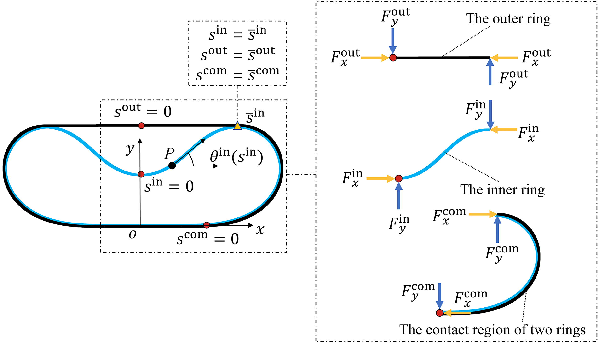
Force diagram of soft robot configuration. The orange triangle represents the separation point of inner and outer rings (blister separation point). The red dots represent the origins of the inner ring, the outer ring, and the contact region of the two rings.
Take the inner ring as the example to derive the static equilibrium equation. The Cartesian coordinates of any point P on the inner ring can be expressed as
Thus, the energy functional of the inner ring containing the bending energy, gravitational potential energy, and the constraint terms can be expressed as
Assuming an infinitesimal virtual deformation of the inner ring curve θξ(sin) = θ (sin) + ξη(sin), xξ(sin) = x(sin) + ξu(sin), yξ(sin) = y(sin) + ξv(sin), where ξ is a small positive parameter, the first order variation of Win can be written as
Considering the arbitrariness of η(sin), u(sin), v(sin), the inner ring needs to satisfy the following equilibrium equations
Similarly, the static equilibrium equations for the outer ring and the contact region of two rings can be obtained as follows:
The structure of the soft robot is symmetric and the boundary conditions θin(0) = 0, θout(0) = 0 are satisfied at the symmetry axis. The boundary conditions θ
By combining the continuity conditions and boundary conditions, the numerical solution of the soft robot configuration can be obtained by using the built-in solver “bvp4c” in MATLAB. One example of the numerical solution of the theory is shown as the black dotted line in Supplementary Figure S1, which is in good agreement with the experiment and verifies the correctness and feasibility of the above buckling model.
According to Equations (4) and (5), the configuration of the soft robot is determined by the stiffness ratio Kin/Kout, the length ratio Lin/Lout, and the gravity of the soft robot, as shown by the configuration map in Supplementary Figure S4. The results show that the stiffness ratio dominates the overall configuration of the soft robot. The large Kin/Kout corresponds to the low gravity center, the large contact area with the ground, good terrain adaptability, and good rolling stability. It should be noted that when Kin/Kout > 10, the effect of Kin/Kout becomes slight. The length ratio dominates the shape of the blister, which may affect the rolling performance of the soft robot and will be shown in Figure 7e. Therefore, the appropriate stiffness ratio and length ratio of the soft robot can be selected to meet the diverse task requirements. In this study, we pursue the balanced performance of the soft robot in terms of rolling velocity, rolling stability, and adaptability to complex terrains, and thus we chose a high stiffness ratio Kin/Kout of 919 and a suitable length ratio Lin/Lout of 1.0452 for the terrain adaptability test.
Rolling mechanism analysis
As shown in the “Locomotion analysis” section, the locomotion of the proposed soft robot is essentially a passive motion driven by the bistable transition motion of the local loading region. Due to the bistable characteristics of the proposed soft robot, which is significantly different from the traditional rolling mechanism, it is necessary to establish a corresponding theoretical model to analyze the critical loading curvature of the soft robot that triggers rolling.
Due to the complexity of directly analyzing the locomotion of the overall configuration, the analysis of the soft robot is simplified to the analysis of the local loading region, that is, to study the bistable mechanism and the critical loading curvature of the local loading region. Taking the motion of the soft actuator A1 in Figure 2 as an example, the initial state and the end state of the soft actuator A1 are represented in Figure 4a. Note that the blister has varied curvature at different positions. By using the zero curvature point (blue dot in Fig. 4a) as the boundary, set the curvature of the green blister region as negative and the curvature of the yellow blister region as positive. Ignore the global displacement and rotation of the loading region, and put the two ends of the loading region of two stable states together (Fig. 4b). It is observed that the local loading region transits between two stable states with opposite curvature signs, and there is an asymmetrical unstable state and a critical state. This feature is similar to the bistable beam driven by symmetrical boundary actuation. 29 The difference is that the bistable structure in this work has a “movable boundary,” and the distance dl between two ends of the loading region is not fixed during the bistable transition.

Since the length of the local loading region sl is much smaller than that of the blister, it can be assumed that the distance dl between two ends of the loading region is fixed, which will be verified by the experiments in the “Analysis of critical loading curvature” section. Based on this assumption, the snap-through buckling phenomenon in the local loading region can be regarded as the saddle-node bifurcation. 29 The method of applying boundary loading angles at two ends can be used to analyze the snap-through transition of the loading region under curvature loading. The change of midpoint deflection ω in the loading region can be used to represent the locomotion of the loading region under boundary loading angle β (Fig. 4b). In this way, our problem becomes to explore the minimum boundary loading angle of the snap-through buckling behavior in the loading region under the fixed distance dl constraint, that is, to study the critical boundary loading angle βc.
According to the static equilibrium equations in the “Static configuration analysis” section, the distance dl between two ends of any loading region on the blister can be solved numerically, where the length of the loading region is fixed at sl = 0.026 m. Then, the equilibrium configurations of the stable and unstable states of the loading region subjected to any boundary loading angle β can be numerically solved by combining Equations (1) and (4) with the distance dl and the boundary condition.
Based on the equilibrium configuration of the loading region, the midpoint deflection ω and normalized strain energy can be obtained for any boundary loading angle β. As the boundary loading angle β increases, the midpoint deflection ω of the loading region changes. When the midpoint deflection of the stable state I is equal to that of the unstable state, the system instantly transits to another stable state (stable state II) with lower energy, and the critical boundary loading angle βc is obtained.
The position of the local loading region influences the critical boundary loading angle, and five loading positions are shown in Figure 4c. Here these loading positions denote the midpoint of the loading region or the soft actuator. The point of zero curvature is denoted as P0 and the point of maximum curvature in the green blister region is denoted as P5. The normalized loading position can be defined as
The theoretical critical loading curvature can be expressed as
The theoretical critical rolling velocity can be expressed as:
According to Equations (9) and (11), the theoretical critical loading curvature kc and the theoretical critical rolling velocity vc of the soft robot are affected by the length ratios Lin/Lout, the loading position spl, and the critical boundary loading angle βc. The length ratios and the loading position determine the initial mean curvature of the loading region, which in turn affects the critical boundary loading angle and the theoretical critical loading curvature. The magnitude of the theoretical critical loading curvature determines the loading pressure, which in turn determines the driving force and rolling velocity of the soft robot. Therefore, different application scenarios, rolling velocity, and driving forces can be considered when selecting appropriate length ratios and loading positions.
Results and Discussion
Analysis of critical loading curvature
Take the soft robot configuration with Kin/Kout = 919 and Lin/Lout = 1.0452 as an example, and the loading position is at P3. The midpoint deflection ω and normalized strain energy of the loading region can be obtained, as shown in Figures 5a and 5b. With the increase of the boundary loading angle β, the midpoint deflection ω of the stable state I of the loading region decreases (Fig. 5a), and the normalized strain energy accumulates (Fig. 5b). When the midpoint deflection and the strain energy of the stable state I are equal to those of the unstable state, the loading region transitions from the stable state I to the stable state II instantaneously, and the critical boundary loading angle βc = 0.514 rad can be determined. After the snap-through transition, the strain energy of the loading region plummets (Fig. 5b).

In order to investigate the effect of the loading position on the critical boundary loading angle βc, the relationship between the midpoint deflection ω and the boundary loading angle β for loading positions P1∼P5 is calculated, as shown in Figure 5c. The loading position closer to the zero curvature point has the smaller critical boundary loading angle βc and the smaller critical loading curvature kc.
The length ratio Lin/Lout affects the geometry of the blister and therefore influences the critical loading curvature kc. By fixing other parameters, the critical boundary loading angle βc of the soft robot with different length ratios Lin/Lout is shown in Figure 5d. Note that the length ratio is tuned by changing Lout and fixing Lin as shown by configurations in Figure 4d. As the length ratio Lin/Lout decreases, the blister structure becomes elongated, the initial mean curvature of the loading region decreases, and the critical boundary loading angle βc decreases. Therefore, the critical loading curvature kc is smaller for slender blister structures with smaller length ratios Lin/Lout.
In order to provide useful guidance on the soft robot design and loading position selection, the relationship between the critical loading curvature kc of the blister and the loading position spl is calculated for three different length ratios Lin/Lout, as shown in Figure 6. For the same loading position spl, the configuration with a larger length ratio Lin/Lout requires a larger critical loading curvature kc. In order to verify the proposed theory, corresponding experiments were conducted by fabricating soft robots with fixed Lin (509 mm), fixed Kin/Kout (919), and varied Lout (480 mm, 487 mm, and 495 mm), as shown by the experiment results in Figure 6. The experimental critical loading curvature of the soft actuator at different loading positions for different length ratios is calculated by Equation (10). In Figure 6, the experimental results are consistent with the proposed theory, which also proves the correctness of the assumption of fixed dl.
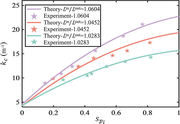
The critical loading curvature kc with different loading position spl for three length ratios Lin/Lout (1.0604, 1.0452, 1.0283).
In the above analysis, it can be seen that the loading position closer to the zero curvature point shows smaller critical loading curvature of the soft robot and smaller loading pressure in the experiment, which corresponds to a smaller driving force to the soft robot. For the loading position selection of the soft robot, appropriate driving force needs to be considered. For example, for complex terrains such as steps and the slope, a larger driving force is required, so the loading position away from the zero curvature point can be selected. In addition, a larger driving force can be achieved by increasing length ratios Lin/Lout with the loading position fixed. However, large length ratios Lin/Lout increase the height of the blister, which is unfavorable to the rolling of the soft robot. Therefore, the application scenarios and the required driving force need to be comprehensively considered in the design and loading position selection of the soft robot to ensure optimum performance in practical applications.
Locomotion performance tests
The adaptability to complex terrain and the rolling performance are important indicators to evaluate a soft robot’s potential for application. A series of experiments were carried out to investigate the rolling performance on flat ground and the locomotion performance in various terrains (steps, the slope, and the broken bridge).
The rolling velocity of the soft robot is related to the loading pressure and loading timing sequence. By using the loading pressure of 55 kPa and the loading timing diagram in Figure 7a, the soft robot moved 500 mm in 2.6 s, with an average speed of 192.3 mm/s or a body length velocity of 0.95 BL/s, as shown in Figure 7b and Supplementary Movie S1. The loading control parameters of the loading timing include the loading pressure P for each actuator, the duration time T of actuation for each actuator, and the overlapping time To between neighboring actuators. Note that if not specified, the soft robot in this section is configured with Kin/Kout = 919 and Lin/Lout = 1.0452, with the loading position at the point of maximum curvature.

In Figure 7c, the effect of the loading pressure P on the rolling velocity (one step of rolling) is shown where only one actuator is loaded to drive one step of rolling and the duration time T is fixed at 1 s. For the tested robot and tested actuator, there is a critical rolling velocity (0.45 BL/S) and a maximum rolling velocity (0.91 BL/S) for one step of rolling. The robot cannot roll when the loading pressure is smaller than the critical value of 40 kPa. When P ≥ 40 kPa, the rolling velocity increases with the increase of the loading pressure until the robot reaches the maximum rolling velocity with P ≥ 55 kPa. Therefore, for each actuator, a loading pressure P between the critical value and the maximum value should be selected for actuation.
In Figure 7d, the effect of the duration time T (yellow line) on the average rolling velocity (continuous rolling) is shown where eight actuators are loaded with P = 55 kPa and To = 0 s. The average rolling velocity decreases with the increase of T. There is a maximum average rolling velocity (0.95 BL/S), which corresponds to a minimum T (0.3 s), as shown in Figure 7b and Supplementary Movie S1. The robot cannot roll when the duration time T < 0.3 s because the loading time for each actuator is too short to drive one step of rolling.
The effect of the overlapping time To (blue line) on the average rolling velocity (continuous rolling) is also shown in Figure 7d, where eight actuators are loaded with P = 55 kPa and T = 0.5 s. The average rolling velocity increases with the increase of To. There is a maximum average rolling velocity (0.85 BL/S), which corresponds to a maximum To (0.2 s). The robot cannot roll when the overlapping time To is over the maximum value as the loading time for each actuator is too short to drive one step of rolling. Therefore, for the fast rolling velocity, small T and large To should be selected, but the control parameters should ensure that the loading duration time for each actuator has a minimum of 0.3 s.
The proposed robot has the critical rolling velocity under the critical loading pressure, which is affected by the length ratio and the loading position. According to Equation (11), the relationship between the theoretical critical rolling velocity vc and the loading position spl is calculated for three length ratios Lin/Lout (1.0604, 1.0452, and 1.0283), as shown in Figure 7e. In order to verify the proposed theory, corresponding experiments were conducted, and the experimental results are shown as the pentagons in Figure 7e. The results show that the critical rolling velocity increases with the increase of the length ratio and the loading position.
In order to further validate the locomotion performance of the soft robot, a series of experimental scenarios were designed to simulate the complex terrains that might be encountered in applications. In the terrain experiments, a large driving force is required for the robot to navigate complex terrains. Therefore, the loading positions of the soft robot are close to the maximum curvature point to obtain a large driving force. The loading timing diagram used in three terrain experiments is shown in Supplementary Figure S5.
The three-stage steps were built with each stage measuring 1.5 cm in height and 20 cm in length. Under the loading pressure of 40 kPa, the soft robot successfully climbed the steps (Fig. 8a), and the average climbing speed was 61.22 mm/s (Supplementary Movie S2). During the climbing process, the configuration of the soft robot hardly changed, and the whole robot body moderately tilted when rolled over the steps tip, which is similar to that of a tank. Compared with the deformation-driven soft robot, 30 our soft robot has a small deformation, low deformation energy consumption, and a smooth locomotion trajectory, which demonstrates its good obstacle-crossing ability in complex terrain.

Schematics of the soft robot navigating different terrains.
The maximum gap length of the broken bridge that the soft robot can cross is 90 mm (Fig. 8b), which is nearly half of the robot’s body length (0.443 BL). Under the loading pressure of 40 kPa, the soft robot crossed the broken bridge with an average speed of 56.25 mm/s (Supplementary Movie S3). Most of the previous rolling soft robot configurations are wheel-shaped, and they easily slip into the broken gap and get stuck. In contrast, the proposed soft robot has a large contact area with the ground due to its two-nested ring structure, and the locomotion stability is improved. Due to the novel rolling mechanism driven by local snap-through buckling, it can keep its configuration stable without significant deformation and does not get stuck when crossing the broken bridge.
The slope with the slope angle of 18.36° was built. Under the loading pressure of 57 kPa, the soft robot climbed the slope with an average speed of 52.63 mm/s (Fig. 8c and Supplementary Movie S4). The slope angles of 10° and 15° were also tested to show the effect of the slope angle on the loading pressure, where the loading timing diagram has the same T and To. The result shows that the larger slope angle requires a larger loading pressure to provide a larger driving force. In literatures, the maximum slope angle that can be traveled by the circular rolling soft robot developed was 5°, 31 and that of the triangular rolling soft robot was 8°. 12 In comparison, our soft robot shows a significant advance in terms of slope climbing ability due to the tank-track-like configuration and the novel rolling mechanism driven by local snap-through buckling.
In addition, a more realistic outdoor scenario was established. The soft robot coherently passed through the cluttered environment, including tree branches, gravel paths, rugged slopes, and the broken bridge (Fig. 8d and Supplementary Movie S5).
The load-bearing capacity of the robot was tested as shown in Supplementary Movie S7, where the robot carried the payload and rolled one step. The experiment result shows that the maximum load capacity of the present soft robot is 42.5 g, and more load capacity can be achieved by using elastic rings with larger stiffness.
Comparison of locomotion performance
The locomotion performance of the proposed rolling soft robot is compared with that of previous rolling soft robots, as shown in Figure 9a. The proposed rolling soft robot has a maximum rolling speed of 192.3 mm/s or 0.95 BL/s, a weight of 83.85 g, and a deformation level of 1.039. In addition, the energy efficiency of the proposed rolling robot is 0.098% compared with 0.016% for the GoQbot 16 and 0.0041% for the DECSO prototype A. 30 The detailed calculation process of energy efficiency is shown in Supplementary Data S1. It is shown that the soft robot in this article has an advantage in terms of the rolling speed, energy efficiency, and mass, which is mainly attributed to the novel rolling mechanism driven by local snap-through buckling that reduces the deformation level of the soft robot during the rolling and thus decreases the energy loss and improves the energy efficiency so that the proposed soft robot can balance the energy efficiency with the rolling speed. In addition, the unique two-nested ring configuration and the bistable characteristics enable smooth two-way rolling on flat ground (Supplementary Movie S6) and successful navigation through complex terrains (the slope, steps, and the broken bridge), which can maintain the current configuration and position when the pressure is unloaded. Therefore, compared with previous rolling soft robots, the proposed soft robot has good locomotion stability and good terrain adaptability.

In order to evaluate the adaptability of rolling soft robots to complex terrains, the different terrains that rolling soft robots can pass are compared, as shown in Figure 9b. Most of the rolling soft robots in the literature can only adapt to one or two terrains due to their locomotion mechanism. Few previous rolling soft robots can cross the broken bridge. In contrast, the rolling soft robot in this study can adapt to complex terrains, including the broken bridge, and can maintain good locomotion speed and energy efficiency during the navigation process. This performance not only shows the adaptability of the proposed rolling soft robot to complex environments but also reflects the advantages of the proposed rolling mechanism.
Conclusion
This article proposes a novel rolling soft robot driven by local snap-through buckling. By applying local curvature to the local loading region, the loading region generates a local snap-through buckling transition, which drives the deformation and rolling of the entire soft robot. As verified by theoretical analysis and experiment, the shape of the soft robot remains almost unchanged during the rolling locomotion, and the energy loss is low. The maximum speed of continuous rolling on flat ground is 192.3 mm/s or 0.95 BL/s, which is faster than most of the previous rolling soft robots. The proposed soft robot can navigate through complex terrains, including a slope with a maximum angle of 18.36°, steps with each stage height of 15 mm, and a broken bridge with a maximum gap length of 90 mm (0.443 BL). The maximum load capacity of the proposed soft robot is 42.5 g, and more load capacity can be achieved by using elastic rings with larger stiffness.
The good rolling performance and excellent terrain adaptability of the soft robot are attributed to the novel rolling mechanism and unique two-nested ring configuration. The proposed rolling mechanism balances high rolling speed with energy efficiency by using the snap-through transition of the local loading region, which enhances the stability and controllability of rolling. The soft robot only drives one actuator to achieve one step of rolling, which simplifies the driving method compared with some previous rolling soft robots10,17,30 loading multiple actuators at each step of rolling. The two-nested-ring configuration of the soft robot resembles the tank track and ensures the high efficiency and stability of the soft robot in the locomotion process. Besides, the designed soft actuator simplifies the nonstretchable layer and realizes the lightweight design of the soft robot. The proposed robot cannot change its height while rolling, but an alternate simple method to change the robot’s height is replacing the outer ring with different lengths and stiffness while the inner ring remains the same.
The proposed rolling soft robot with tethers has good application prospects in medical services 30 by carrying the inspection device and rolling on the body of the patient on the bed, which is similar to the medical application of the reported soft robot DECSO. 30 Other potential applications, such as land exploration, may require an untethered version of the robot. As preliminary research, this article mainly studies the rolling mechanism of the proposed robot with the tethered pneumatic control. However, the pneumatic actuation method and the big number of actuators make it difficult to integrate the untethered soft robot with all components on board. Using other suitable actuation methods with small size and small mass, for example, cable actuation 39 and electric actuation 40 can facilitate the untethered integration of the proposed rolling robot in future works. The proposed new rolling mechanism with the bistable structure is anticipated to bring new inspiration to the development of soft robots.
Footnotes
Author Disclosure Statement
The authors declare that they have no known competing financial interests or personal relationships that could have appeared to influence the work reported in this article.
Funding Information
This work was supported by the
References
Supplementary Material
Please find the following supplemental material available below.
For Open Access articles published under a Creative Commons License, all supplemental material carries the same license as the article it is associated with.
For non-Open Access articles published, all supplemental material carries a non-exclusive license, and permission requests for re-use of supplemental material or any part of supplemental material shall be sent directly to the copyright owner as specified in the copyright notice associated with the article.