
Abstract

Introduction
One major advantage of ion-beam therapy in comparison to other radiation therapy techniques is the improved conformation of RBE-weighted dose to the clinical target volume (CTV) due to physical and biological characteristics. This is characterized by a absorbed dose vs. depth profile exhibited by a mono-energetic beam with a relatively low absorbed dose in the entrance region (plateau) and a sharp dose peak (Bragg peak) at the end of the finite range (which can be spread out to match the longitudinal extent of the PTV), little lateral scattering, and increased RBE in the target volume in comparison with the entrance region.
To maintain the advantage of conformity over a course of ion-beam therapy, in addition to accounting for uncertainties due to beam parameters (e.g., position, spot size) that are discussed in Section 8, the target volume has to be positioned precisely for each treatment fraction. Two types of possible anatomical variations have to be considered to achieve adequate target volume positioning: (1) inter-fractional organ motion and (2) intrafractional organ motion. Apart from these internal changes of the patient's anatomy, misalignment of the patient itself is typically constrained by dedicated immobilization equipment. In addition, imaging techniques in the treatment room may be employed to register the actual patient position to the planned position. Interfractional target motion occurs in a time-scale of hours to weeks, e.g., weight loss or radiation-induced effects such as tumor shrinkage, whereas intrafractional target motion occurs in a time-scale of seconds to minutes, e.g., respiration. An overview of organ motion and its management in radiation therapy is given elsewhere (Bert and Durante, 2011; Korreman, 2012; Langen and Jones, 2001).
The management of motion in ion-beam therapy depends on the motion type. Ion-beam therapy should not be delivered to patients for whom adequate mitigation of motion and setup errors cannot be established. The following sections cover immobilization and patient positioning techniques (some of which are ion-beam-therapy specific) including imaging for treatment planning and patient position verification that deal with inter-fractional as well as intrafractional motion.
Patient Positioning
Precise patient positioning is a crucial aspect of treatment delivery since potential benefits of high-precision ion-beam therapy can only be realized if the patient is precisely set up in the treatment beam according to the coordinates determined by the treatment plan. Typically, special immobilization devices are used to ensure that the patient does not move during treatment. Positioning of the immobilized patient in the treatment room is performed by a radiotherapy couch or a robotic arm – both systems allow translations and rotations with respect to the treatment isocenter. The position of the patient is determined using methods that can range from alignment of skin marks with an orthogonal laser projection system to accurate registration of a volumetric image in the treatment position to the treatment planning CT data. The following sections cover details of positioning, immobilization, and positioning verification.
Treatment Couch or Robotic Arm
The treatment couch is used to move the patient precisely relative to the isocenter in the treatment room. For ion-beam therapy treatment, two types of couches are used, viz, couches in treatment rooms with fixed beam lines where the treatment beam does not penetrate the couch; and couches in treatment rooms that are equipped with an isocentric gantry where the beam can penetrate the couch. Couch tops require mechanical stability as well as compatibility with kV x-ray imaging modalities. As an alternative to classical treatment couches, robotic arms can be used. Another possibility to increase the number of available treatment directions is the use of a dedicated treatment chair in which patients are immobilized and positioned in a sitting position.
At ion-beam therapy facilities, most fixed beam lines are horizontal. At some facilities, a horizontal beam line is combined with oblique (Hyogo Ion Beam Medical Center− HIBMC) or vertical (NIRS, HIBMC, Gunma University Heavy Ion Medical Center − GHMC) beam lines that irradiate the patient from above and do not penetrate the couch top. Due to the limited choice of treatment directions offered by fixed-beam installations, treatment couches that allow roll and pitch rotations in addition to translations and rotation about the vertical axis are preferable. With six degrees-of-freedom movement, couch rolls (typically up to ±15°) enable irradiations from a range of directions. In these installations, the couch top does not require ion-beam specific features since the beam does not penetrate it.
Figure 7.1 shows the couch at NIRS that allows rolling up to ±20°. The robotic arms at HIT allow translations and rotations including pitch (up to ±15°) and roll (up to ±15°).

Patient positioning for lung treatment on the horizontal beam line at NIRS. Patient treatments with oblique beam angles are achieved by rolling the couch up to ±20°.
Isocentric gantries are available at HIT and at NIRS (see Section 3). The use of isocentric gantries requires couch tops that are not only compatible with imaging modalities but also with the treatment beam. Due to the strong influence of material in the beam path on the particle range, the effect of the couch top has to be incorporated into the treatment plan whenever the beam penetrates it. Thus, couch tops with homogeneous material composition and minimal thickness are preferred. Ideally it should be possible to accurately model couch tops in the treatment planning system either by using a fixed water-equivalent thickness or by including a detailed model of the table top.
Immobilization devices are used for two main reasons: first, to achieve a reproducible and precise patient position during the course of the radiotherapy treatment from the initial imaging for treatment planning until the last irradiation of a fractionated treatment; and second, they ensure that the patient remains stationary during each treatment fraction. Changes in patient position can lead to ‘geographic misses’ and change the radiological path length to the target volume. Either effect can reduce the conformity.
In general, patients are immobilized in supine, prone or even oblique positions to optimize the incident beam angles. For example, for patients treated for head and neck lesions the head can be immobilized in a specific rolled and/or tilted position to provide optimum beam entrance channels. In addition, immobilization devices should guarantee that the patient is reproducibly positioned. The combination of these constraints requires rigid, patient-specific immobilization devices that can be readily fabricated. Ideally, the beam does not penetrate the device so as to avoid any influence on the beam range, but in practice this can often not be avoided. If the device is to be penetrated, the material should be chosen such that it is compatible with the imaging modalities (size and avoidance of imaging artifacts) and that in addition, the properties of the ion beam are considered. The ion-beam properties require radiologically thin and homogenous devices that are ideally also compatible with the Hounsfield unit (HU) lookup table used for treatment planning (Jäkel et al., 2001; Kanematsu et al., 2003) (see also Section 6.3 of the present Report).
Materials used and type of immobilization devices depend on the treated site. They can range from support devices such as specially shaped pillows for holding the legs of the patients in a specified position to thermoplastic polymers used to form, for example, head masks that rigidly attach the patient to the couch. Most systems available for standard radiotherapy can also be used or at least adapted for patient immobilization in ion-beam therapy. Specific examples are the extremely rigid fixation masks originally developed at the German Cancer Research Center (Schlegel et al., 1992) that were used at GSI and initially at HIT, and the semi-cylindrical body capsule used at NIRS (Tsujii et al., 2004) that immobilizes and positions the patient in an oblique position on the treatment couch and on the CT scanner couch (see Figure 7.1). Of importance and different to photon beam therapy is the potential range influence of immobilization devices that needs to be considered in the construction of such devices and during treatment planning.
Positioning and Position Verification
For therapy positioning, the patient is immobilized using the device previously fabricated for the imaging session for treatment planning. The goal of positioning is the alignment of the target point within the patient which is defined during treatment planning to the isocenter of the treatment beam. On the first treatment day, or in a dedicated treatment simulation session, the patient is positioned using stereotactic or imaging methods. Both methods correlate the coordinate system from imaging and treatment planning to the coordinate system of the treatment room. After this original setup, the required alignment reference points of the patient in the treatment room can be marked on the immobilization device or on the patient by using an orthogonal-laser projection system that indicates the treatment room coordinate system including the isocenter. For all remaining treatment fractions, patient positioning is then simplified because the patient is initially aligned within the treatment room based on these marks. Another possibility is to reproducibly register the immobilization device with the couch top. Then initial patient positioning can be performed using absolute couch coordinates in the treatment room to reduce the time required for patient setup with a laser system. Either way, the position of the patient needs to be further verified prior to treatment delivery, e.g., by orthogonal x-ray imaging (see below).
Stereotactic patient positioning was originally proposed for radiosurgery (Leksell, 1951); an overview is given by Benedict et al. (2008). For precise positioning, a stereotactic frame is rigidly attached to the patient prior to imaging for treatment planning as well as prior to treatment. The stereotactic frame defines a patient-specific coordinate system that can then be matched to the imaging or the treatment room coordinate system. For carbon-beam therapy at GSI and initially at HIT, the stereotactic system developed by Schlegel and others was used (Karger et al., 2001b; Schlegel et al., 1992). Currently, HIT facilitates immobilization by thermoplastic masks (Jensen et al., 2012).
In the stereotactic system of Schlegel et al., the frame is fixed to the patient via a rigid head mask and not by bolts. Alignment by a stereotactic frame is limited in precision due to the interfractional changes within the immobilization device such as slight movement of the patient within a head mask. Stereotactic positioning is time-intensive and thus typically used on the first treatment day only to provide reference marks that allow patient positioning using the laser alignment system of the treatment room for the remaining treatment fractions.
To further improve the precision of the techniques mentioned above, image-guided radiotherapy (IGRT) methods can be applied to align the immobilized patient based on the anatomy. Several imaging modalities are available for this purpose (reviews in Chen et al., 2009; Evans, 2008). The most common imaging option for verifying the precise alignment of the immobilized patient is radiography. Orthogonally acquired x-ray images of the patient in the treatment position show the bony anatomy. These projection images can then be compared to e.g., digitally reconstructed radiographs (DRRs) that are generated from the treatment planning CT scan data (2D–2D registration). After DRR-based positioning during the first treatment fraction or the simulation session, verified x-ray images which allow easier comparison due to improved image quality compared to DRR can be used as reference on subsequent treatment days instead of the DRRs. Apart from pre-calculating, the DRRs from the treatment planning CT, the DRRs can also be generated dynamically at time of imaging. Then slight patient rotations can be incorporated in the registration of DRR and x-ray image. Online DRR generation followed by this 2D–3D registration can therefore accurately determine slight rotational setup errors. This registration method is fully automated in several carbon-ion therapy installations (Jensen et al., 2012; Mori et al., 2015). In general, this comparison of reference data and positioning images can also be done manually and/or software-aided. Anatomical landmarks or comparison of the CT numbers can be used to determine possible required positional corrections. The results are 3D position displacement parameters including rotational degrees of freedom that are used to adjust the position of the immobilized patient by moving the couch or robotic table.
Volumetric imaging of the immobilized patient in combination with contrast-enhanced soft-tissue visualization can achieve higher precision for determining the patient position. In conventional photon-beam therapy volumetric imaging with the patient in the treatment position is frequently performed with cone-beam computed tomography (CBCT) (Jaffray et al., 2002). Any required couch translations and rotations are determined by registering the CBCT to the treatment planning CT data. As an alternative to CBCT, CT scanners that are installed in the treatment room have been used (Hua et al., 2003; Kamada et al., 1999; Lattanzi et al., 1998; Thieke et al., 2006; Uematsu et al., 1996). With these methods, the patient is imaged in the same position used for treatment delivery, e.g., by a CT scanner on rails that slides over the immobilized patient or by moving the couch from the treatment position to the CT scanner. A robot-based CBCT system is used at CNAO for patient positioning (Fattori et al., 2015) and technically available at HIT (Heiland et al., 2005) and MedAustron (Zechner et al., 2016). Also, some proton therapy centers allow CBCT-based patient positioning (Landry et al., 2015; Veiga et al., 2016), but currently (2016) positioning of the immobilized patient based on volumetric image data is not yet widely used in ion-beam therapy. One exception is in-room CT-based positioning at the i-Rock center in Kanagawa, Japan.
An alternative to patient immobilization and positioning inside the treatment room is a shuttle system that moves the immobilized patient including the couch top from external volumetric imaging scanners, e.g., the treatment planning CT scanner, to the treatment room (Bolsi et al., 2008; Hof et al., 2003). Precise alignment can be achieved by using a couch top that can be employed during imaging as well as for irradiation. This requires a precision docking system on the scanner as well as on the treatment couch or robotic arm. In addition to providing more efficient use of the treatment rooms and of the technical infrastructure, diagnostic CT scanners typically give better image quality than a CBCT in the treatment room. A shuttle system can furthermore be used to transport the immobilized patient to a CT or PET scanner directly after the administration of a treatment fraction to allow measurements for quality assurance (see below).
Interfractional Changes
Interfractional motion influences fractionated treatments and occurs in time periods varying between hours and days. Typical causes for inter-fractional motion are bowel or bladder filling, tumor regression, healing processes after surgery, and changes in the patient's weight. One typical site influenced by interfractional motion is the prostate. Prostate motion was studied by Chandra et al. (2003) for 147 patients treated with IMRT. Based on ultrasound measurements they reported an interfractional standard deviation for setup error and internal motion of 4.9 mm/4.4 mm/2.8 mm in AP/SI/RL directions, respectively. These findings of Chandra et al. are in agreement with the data of a review by Langen and Jones (2001). Their review of the literature data shows, that motion is largest in AP and SI directions. Standard deviations of 1.5–4.1 mm (AP), 0.7–1.9 mm (lateral), and 1.7–4.5 mm (SI) were reported by the studies contributing to their analysis.
For ion-beam therapy, both lateral motion components and changes in radiological path-length have to be considered. Changes in radiological path length occur along the beam path and can lead to changes in Bragg-peak positions with potentially great dosimetric impact. Reported factors leading to changes in radiological path length are weight loss (Albertini et al., 2008) and mucus filling status of nasal or paranasal sinuses (Enghardt et al., 2004a). In both cases, the penetration of the particle beam was significantly changed.
To increase the interfractional reproducibility of internal anatomy, several schemes that reflect the diverse origin of interfractional changes can be used to prepare the patient. Common sites for inter-fractional motion are malignancies in the genitourinary and gynecological system where bowel and bladder filling have an impact on internal anatomy. The status of these organs can be partially controlled by drinking, eating, and/or voiding schemes, rectal balloons (Slater et al., 1998; Wachter et al., 2002), or the use of laxatives or enemas to control rectum filling (Tsuji et al., 2005).
In addition to the schemes mentioned above treatment planning margins (see next section) must ensure adequate coverage of the CTV with the prescribed RBE-weighted dose. Introducing image-guidance techniques (Section 7.3.2) with soft-tissue contrast provides the possibility of reducing uncertainties related to interfractional changes. Details of these two topics will be provided in the next sections.
Treatment Planning Margins
Internal margins around the CTV that contribute to the planning target volume (PTV) are used throughout radiation therapy to help ensure adequate dosage in the CTV (ICRU, 1993b, 1999). Internal margins have to take account of the lateral extent of the uncertainties of tumor or organ position. An overview has been published by van Herk (2004). In ion-beam therapy margins further need to include possible range uncertainties. Range uncertainties are in general field specific because they depend on the tissues traversed by the beam. It is recommended that the choice of margins is validated before clinical use. The suitability of margins can be assured for example in dedicated treatment planning studies. In these studies, the robustness of treatment plans against some of the expected uncertainties is determined by multiple dose calculations each with different input parameters within the expected range (Ammazzalorso et al., 2014; Böhlen et al., 2012; Graeff, 2017; Houweling et al., 2016). Parameters include slide variations in patient position. Assessment of interfractional motion sensitivity is patient specific and e.g., based on multiple CTs of the patient in different motion states (e.g., with different rectal filling). Assessment of the RBE-weighted dose distribution then reveals the capability of the applied treatment planning margins in allowing for expected uncertainties (Lomax, 2008b). One option to deal with such uncertainties is robust treatment plan optimization that has been studied for multiple sites in proton and ion-beam therapy (Cao et al., 2012; Chen et al., 2012; Inaniwa et al., 2011; Unkelbach et al., 2009).
For ion-beam radiotherapy of prostate cancer at GSI, multiple CT datasets were acquired on different days prior and for treatment planning. The prostate target volume and tissues in the entrance channel are imaged in different interfractional motion states. For treatment planning, three to five CT scans were acquired and used to form a patient-specific PTV by contouring of the target volume on each scan and selecting those target voxels that were included in at least two of the individual target contours (Figure 7.2). This geometrically constructed PTV was used for treatment plan optimization on a representative CT scan. The treatment planning concept was successfully validated for prostate cancer in a treatment planning study in which the optimized treatment plans were applied to all available CT data sets for each patient to assess the resulting RBE-weighted dose distributions. The treatment protocol also includes specific patient-positioning techniques that, for example, ensure identical positioning of the femoral heads between fractions to reduce or even eliminate motion-induced range changes caused by high-density bony structures in the beam paths. In recent years, studies investigated the insertion of a spacer gel between the prostate and rectum which serves as an artificial margin for the main OAR and dissolves a few weeks after treatment (Habl et al., 2016; Rucinski et al., 2013, 2015). Due to the development of fistulas, however, this treatment setup was stopped (Habl et al., 2016). Silicon spacer placement is used at CNAO in Pavia, Italy for patients treated for sacral chordoma to increase the distance to organs at risk close to the tumor volume (Lorenzo et al., 2016).

ITV generation for prostate treatments. Use of multiple CTs for prostate therapy treatment planning at GSI/HIT. The input data for treatment planning are generated from five CT scans typically acquired on five different days prior treatment. No rectal balloons were used. Target volumes (GTV in green, CTV in red) and the rectum as the dominant organ at risk (blue) are delineated on each of the five data sets. For treatment planning all five contour sets are combined to form GTVPlan, CTVPlan, and OARPlan by including all voxels of the CT that are included in the respective volume in at least two of the five CTs. Currently, range determination is based on a single, i.e., the most representative, of the five CT scans (CTPlan)
To consider interfractional changes such as tumor shrinkage and internal position variations, several CT scans over a course of treatment can be acquired to revise the CTV and, if needed, repeat the treatment planning. An overview of such adaptive treatment approaches that can result in a reduction of margins is given for photon beam therapy by Yan et al. (2005). For uterine cervix treatments at NIRS, two or three CT scans are performed over a course of treatment to revise the CTV due to interfractional tumor shrinkage (Kato et al., 2006). Application of adaptive treatment schemes is eased by introduction of beam scanning since fabrication of patient specific hardware is not required. At NIRS, an extension of this scheme was therefore proposed after introduction of pencil-beam scanning (Nagano et al., 2012).
The irradiation method dictates how the margins are applied. For passively modified beams, margins in the lateral direction are realized by lateral widening of the aperture. Margins in depth are achieved by reducing the thickness of compensator material according to the expected ion-beam range uncertainties − this results in a distal extension of the particle range that ensures that the desired RBE-weighted dose covers the target volume. Furthermore, to account for possible range variations due to lateral position or motion uncertainties, a treatment planning method referred to as ‘compensator smearing’ is used. In this process, the compensator is expanded or opened up in such a manner that its thickness at any point in the field is the least thickness of the unexpanded compensator within some defined radius – which is typically at least a few millimeters and depends on the uncertainties in the treatment process (Urie et al., 1984).
For scanned-ion beams, no range compensators or apertures are usually used. In a similar fashion to aperture widening in passively shaped ion beams, geometrical lateral margins can be incorporated by applying additional pencil beam positions within the planned margins in each iso-energy slice. Distal range margins can be implemented by extending the grid of beam positions in the beam's eye view. This translates to additional grid points with a greater range. The combination of lateral and range margins can be achieved by extending grid positions to the specified lateral and range margins of the PTV.
Patient-specific determination of lateral and longitudinal treatment planning margins can be achieved if multiple CT datasets that represent internal motion are available. Port specific treatment planning margins can then be constructed by combining the CTVs of the different CT data sets after transformation to a water-equivalent representation (see Figure 7.3). This technique simultaneously incorporates lateral as well as longitudinal range margins that account for interfractional target motion. Additional margins that represent, for example, treatment technique-related uncertainties can be incorporated similarly in the water-equivalent representation. More details on that ITV construction method are provided in Section 7.4.2.

Generation of particle-specific internal target volumes (ITV). The motion states of the underlying 4DCT are used to generate ITVs. In this schematic example only three motion states (a–c) are illustrated each with a few voxels only. Voxel density (i.e., HU value) is uniform apart from gray voxels that represent double dense areas. (a) In geometrical space, the different motion states of the target (hatched areas, ‘a’–‘c’) can be combined to an ITV (denoted as ‘itv’). This is not sufficient since the tissue traversed in the entrance channel can result in density variations that are not incorporated in this geometrically formed ‘itv’. If density variations in the entrance channel are incorporated as shown in (b) water-equivalent representations ‘A’–‘C’ and the corresponding internal target volume in water-equivalence (‘ITV’) can be formed. Due to different composition of tissues in the entrance channel, these water-equivalent ITVs are beam specific. (c) shows the ‘ITV’ for a different beam port than (b) resulting in a differently shaped ‘ITV’. [Technique and figure based on Rietzel and Bert (2010)].
Image guidance to position interfractionally moving soft-tissue targets directly for each treatment fraction is typically based on x-radiographs to estimate the tumor position based on bony anatomy in the vicinity. For sites that suffer from insufficient image contrast in the vicinity, x-ray projection imaging can be supplemented by implanted radio-opaque markers (Nomiya et al., 2008; Shirato et al., 2003). The use of high-density marker materials has to be considered and planned carefully due to the strong influence on the quality of the treatment planning CT data and on the RBE-weighted dose distribution (Jäkel, 2006; Schulz-Ertner et al., 2007). Among five different commercially available markers, no type was suited for ion-beam therapy mainly due to influence on the treatment field (Habermehl et al., 2013b). If implanted lateral or distal of the treatment fields, markers can and were used in the past. Implanted fiducial markers have been used at NIRS for lung, liver, and renal treatments. For example, iridium seeds were used during the ion treatment of renal cell carcinoma (Nomiya et al., 2008). The seeds were implanted in the ipsilateral renal cortex around the tumor and allowed positioning of the target volume by x-ray imaging. Alternatives to x-ray projection imaging are available in photon beam therapy and are expected to be introduced for ion-beam therapy soon. One option is CBCT or conventional CT of the immobilized patient as described for patient positioning in Section 7.2.3. Alternatively, 3D ultrasound as a non-ionizing imaging option provides data that allow organ detection for comparison to reference images or organ contours from treatment planning (Bouchet et al., 2001; Lattanzi et al., 1999). Non-volumetric data can also be obtained by the use of radio-frequency implants that can be tracked in 3D in real-time with an external detector (Balter et al., 2005; Seiler et al., 2000; Willoughby et al., 2006a). For prostate positioning a localization accuracy that is comparable to that of x-ray imaging has been reported (Willoughby et al., 2006b). Tests of such systems in particle therapy environments are ongoing. Of concern is the possible impact on the absorbed dose distribution (Tang et al., 2013), the potential damage to the transponders due to the high LET of ion beams especially in the Bragg peak region, and the varying radiofrequency background in cyclotron or synchrotron-based facilities.
Positioning of interfractionally moving targets has to be in agreement with margin design, i.e., margins for positioning based on bony anatomy might differ from margins for image guided soft tissue positioning. This is due to potential range changes resulting from differential motion between e.g., bony anatomy and CTV that can result in perturbation of the RBE-weighted dose distribution.
A retrospective image-guidance technique is positron-emission tomography (PET), which has been successfully used to assess the treatment quality after each fraction for more than 400 patients treated with a scanned carbon beam at GSI (Enghardt et al., 2004a). For 12C irradiations, nuclear fragmentation within the patient produces 11C and 10C radionuclides that can be used as PET tracers. Apart from these nuclides target atoms also undergo nuclear fragmentation resulting in formation of positron emitters (such as 15O) (Enghardt et al., 2004a, 2004b; Inaniwa et al., 2006, 2008; Parodi, 2004). The annihilation distribution of the positron emitters can be modeled as part of the treatment plan. To assess interfractional changes, measured distributions are compared to the modeled distributions (Figure 7.4). In case of changes which could result, for example, from a change in mucus filling of cavities, a new CT scan followed by generation of a new treatment plan for the subsequent fractions can be considered.

Use of in-beam PET at GSI. (a) Based on the treatment planning CT scan, the expected β+-activity distribution is calculated with a dedicated Monte-Carlo code (Pönisch et al., 2004). After each treatment fraction, this expected activity distribution is compared to the measured one with an example distribution shown in (b). In the specific case displayed, prominent deviations between the two distributions can be observed. Depending on the dosimetric impact of the detected changes a re-scan of the CT and re-planning can be considered. [Data from Parodi (2004)].
If volumetric imaging is implemented for positioning the target volume for each treatment fraction, the adaptation approach currently performed with PET imaging after each fraction can also take account of anatomical changes. Such adaptive treatment schemes include attempting to adjust the beam parameters to compensate for interfractional changes and have been implemented for photon beam therapy [see several reviews in Seminars in Radiation Oncology, April 2010, e.g., (Sonke and Belderbos, 2010)]. Use of daily volumetric imaging for plan adaptation is also likely to be developed specifically for ion-beam therapy. As described below plan adaptation can be performed in different ways, for example, the plan-of-the-day concept (Chen et al., 2013a), the daily adaptation of treatment plans based on CBCTs (Kurz et al., 2016a), and online replanning (Chen et al., 2013b; Hild et al., 2016). If treatment planning (e.g., prostate treatments at GSI/HIT, see Section 7.3.1) is based on multiple CT data sets that represent different interfractional motion states, each individual CT data set can be used to optimize a treatment plan that is optimal for the motion state represented by the CT. For treatment delivery one of these pre-calculated treatment plans can be selected based on a comparison between the daily volumetric imaging data and each of the multiple CT datasets used for treatment planning. Metrics for comparison might include similarity measures as used in registration algorithms. Selection of the treatment plan that was optimized for the imaged anatomy that best matches the actual anatomy corresponds to selection of the best treatment option for a specific day (plan-of-the-day) (Chen et al., 2013a). Of concern is quality assurance for such online or even-real time adaptive protocols that will require detailed analyses and corresponding developments prior being clinically introduced.
For fractionated treatments, treatment plan adaptations can also be based on calculation of RBE-weighted dose distributions actually delivered. RBE-weighted dose calculations can be performed with anatomical information acquired during the treatment fraction or by including data from treatment records. In case of deviations from the planned RBE-weighted dose distribution, a new treatment plan that compensates for the deviations can be optimized for the remaining treatment fractions. A possible intermediate solution would be to use the daily anatomical data for a particle range check only without full RBE-weighted dose calculations (Bentefour el et al., 2015; Kim et al., 2017).
The most advanced use of daily image data is optimization of a treatment plan for the actual anatomy while the patient is immobilized on the treatment couch. This technique has been reported for photon therapy several years ago (Letourneau et al., 2007) and is currently in detailed investigation with respect to MR-guided photon therapy (Acharya et al., 2016). Since no fundamental changes are expected, field geometries and possibly even intermediate optimization results from the initial treatment plan or from treatment plans used for previous fractions can be used as a starting point for the daily optimization. This approach should lead to the most conformal RBE-weighted dose distribution with best sparing of normal tissues but poses many challenges, e.g., online contouring of target volumes and organs at risk and use of fast and robust optimization techniques that have not yet been implemented for ion-beam therapy. As long as fast optimization of treatment plans is not available, adaptations of a treatment plan according to the daily anatomy could be employed. For example, for scanned-beam ion therapy, each individual pencil-beam position could be adapted according to the actual anatomy. This could be achieved by deforming the (CB)CT of the treatment day to register it with the CT data that was used for treatment planning (Kurz et al., 2016a, 2016b). The resulting deformation field could be applied to the pencil-beam positions for adaptation to the actual target shape and position. In beam's eye view, lateral motion components can be adapted directly. However, for longitudinal motion components or changes in density, adaptations cannot be performed purely geometrically, but have to include possible adaptations of the required particle energy. Initial advances are also foreseen in commercially available treatment planning systems.
Intrafractional organ motion occurs on a time-scale of seconds to minutes and thus is likely to degrade RBE-weighted dose conformation in scattered as well as scanned ion-beam therapy. The most prominent cause of intrafractional motion is respiration. For lung tumors, respiration leads to tumor motion larger than 5 mm along SI, lateral, and AP direction in 39.2 %, 1.8 %, and 5.4 % of all patients (Liu et al., 2007). The intrafractional motion of lung tumors has an interfractional component that e.g., results in variation of respiratory motion baseline. Sonke et al. (2008) assessed trajectory shape variations by analyzing CBCT data acquired at each fraction over the course of photon treatment. They determined a minor variability (1 SD) at exhale and inhale of well less than 1.5 mm (1 SD). With respect to tumor motion baseline Sonke et al. reported systematic errors of 1.6 mm, 3.9 mm, and 2.8 mm and random motion components of 1.2 mm, 2.4 mm, and 2.2 mm each in lateral, SI, and AP directions, respectively. For more details on intrafractional organ motion and its management in radiotherapy in general, the reader is referred to the literature (Bert and Durante, 2011; Chen et al., 2007; Langen and Jones, 2001).
For irradiations with passively shaped beams, the effects of intrafractional motion can be mitigated by designing treatment planning margins following the concepts described in Section 7.3.1 for inter-fractional motion. In principle, the magnitude of the different components of the intrafractional motion can be used to determine lateral geometrical margins as well as longitudinal range margins to ensure adequate RBE-weighted dose coverage of a moving target volume. One example where motion coverage by margins does not reflect range uncertainties is the lung where the radiological path length of tumor and surrounding lung tissues differs significantly. Koto et al. (2004) thus manually manipulate the CT by copying the HU values from the GTV in SI direction such that the tumor mass is elongated in this major motion direction replacing less dense lung tissues. An alternative method introduced by Mori et al. (2008) is based on 4DCT data. They merge compensator data for individual motion states to form a field-specific compensator that incorporates motion-related range deviation (Figure 7.5).

Design of a range compensator for gated treatment. (a) Schematic drawing of the PTV as a function of respiratory phase. In gated treatment, the beam is on when the target is at T40 % to T60 % (gating window). (b) Three types of compensating boluses (BolusT40 % to BolusT60 %) were designed by using respective PTVTn. These boluses were combined to make the bolusgated. [From Mori et al. (2008)].
For layer-stacking irradiation (Kanematsu et al., 2002) and scanned ion-beam applications (Haberer et al., 1993), the effects of the interference of intra-fractional target motion with the dose delivery process, typically referred to as interplay, can lead to severe deviations in the delivered RBE-weighted dose distribution, e.g., under-dosage within the CTV (see Figure 7.6) (Bert et al., 2008; Bortfeld et al., 2004; Grozinger et al., 2006; Gueulette et al., 2005; Phillips et al., 1992). The use of treatment planning margins only does not allow mitigation of the dosimetric impact of interplay. Margins must be used in combination with dedicated beam application techniques such as gating, tracking, or rescanning. Possible alternatives, especially for small target motions, have been reported in the literature and include breathing maneuvers such as active breath control during which the airflow to/from the patient is stopped at defined levels (Wong et al., 1999) or deep inspiration breath holding (Hanley et al., 1999). Alternative respiration constraints can be used, e.g., by systems proposed by Hof et al. (2003) and Negoro et al. (2001) that minimize abdominal motion by a plate compressing the abdomen. The Rinecker Proton Therapy Center (RPTC) in Munich treats intrafractionally moving targets with a scanned (proton) beam employing apnea under anesthesia to constrain target motion (Eckermann et al., 2011).

Formation of interplay. In the presence of target motion, raster scan beam delivery results in deterioration of the absorbed dose distribution. During beam scanning along the scan path (white line) within an iso-energy slice that is determined during treatment planning, the target moves as indicated by the blue, orange, and green motion phases and the motion signal in the bottom line. The scanning process delivers the pencil beams to stationary room coordinates. Target motion then changes the relative positions between pencil beams in the target volume. The result is a deteriorated absorbed dose distribution as shown on the right. [According to Bert et al. (2008)].
Prerequisites for successful irradiation of intra-fractionally moving targets are precise patient positioning as well as adequate mitigation of the inter-fractional target motion components. Determination and mitigation of interfractional motion for intrafractionally moving targets can be performed using the data obtained by imaging the target volume at specific intrafractional motion states. For example, for targets that are subject to respiratory motion, imaging at end-exhale provides the possibility of determining daily interfractional shifts of the intrafractional motion trajectory. The required image data can be acquired by gated radiography, e.g., by triggering the image acquisition based on monitoring of the respiratory motion as it was used at NIRS for several years (Minohara et al., 2000).
The following subsection covers details of motion monitoring that is required for several of the delivery techniques followed by detailed description of gating, rescanning and beam tracking that are currently discussed for treatment delivery.
Motion Monitoring
For beam application techniques such as gating and beam tracking, monitoring of intrafractional motion is also required during treatment delivery. Current motion-monitoring systems are not ion-beam therapy specific [reviews in (Keall, 2011; Riboldi et al., 2012)]. External motion-monitoring systems typically monitor surrogates of the target motion like chest wall motion or the volume/temperature of the exhaled air. Several systems are commercially available. A possible disadvantage is the potential disagreement between measured surrogate motion and actual target position or motion. For gated carbon ion-beam treatments at NIRS, an active sensing system, which consists of a position-sensitive detector (PSD) and an infrared-emitting light marker, has been used for more than 20 years to monitor the motion of the chest wall (Minohara et al., 2000).
Direct measurement of tumor motion can be achieved by fluoroscopy with (Shirato et al., 2004) or without (Cui et al., 2007; Schweikard et al., 2005) implanted fiducial markers and is also used for proton therapy (Shimizu et al., 2014; Shirato et al., 2012). The use of marker-less motion monitoring for gated lung and liver treatments is currently investigated at NIRS (Mori, 2014; Mori et al., 2016). Alternative techniques under investigation are the use of ultrasound (Prall et al., 2014; Schwaab et al., 2014) or implanted transmitters that can be localized by external radiofrequency detectors (Balter et al., 2005; Seiler et al., 2000; Willoughby et al., 2006b).
Gating
In gated irradiations, dose delivery is synchronized with the intrafractional motion that is detected by a suitable motion monitor as discussed above. Synchronization means that the beam is only turned on if the motion is within a pre-defined gating window, which is a specific fraction of the motion period determined either by the amplitude or by the phase of the respiratory signal. Figure 7.7 shows the examples of data acquired at NIRS: the motion trajectory (Figure 7.7a), the gating threshold (Figure 7.7b), and the resulting gating window (Figure 7.7c). These data indicate that for synchrotron-based irradiations the pulsed-extraction pattern describes another gate (Figure 7.7d), and only if the gating window and synchrotron pulse coincide, particles are extracted (Figure 7.7e).

Principle of gating. Timing chart of gated irradiation, displayed as a function of relative voltage of the various data acquisition systems versus time. Gated delivery is based on a respiration signal from the patient shown in (a). The physician prescribes a threshold level for gating (b). If the respiratory signal is smaller than this threshold, the beam is requested [gate signal shown in (c)]. If request and duty cycle of the beam extraction from the synchrotron (shown in (d) as voltage pattern of the bending magnet in the synchrotron ring) overlap, the beam is actually extracted and delivered to the patient. It thus can be measured in the dose monitors (e). More detailed description is provided in the main text in Section 7.4.2. [From Minohara et al. (2000)].
The gating window is often defined at the outset of the treatment course especially if acquisition of the treatment planning scan is performed using gated imaging. At NIRS, the gating window is on average defined by a 40 % to 50 % per exhalation duty cycle (Mori et al., 2016), since exhalation is the most reproducible respiratory state (Balter et al., 1998; Ritchie et al., 1994). This choice is appropriate for patients with a regular respiratory pattern (Figure 7.8a). However, since most patients have an irregular breathing pattern that involves amplitude variations rather than in variations of the actual, internal respiratory cycle, the gating window is readjusted manually during irradiations (Figure 7.8b). This approach assumes that the external respiratory signal and the internal target position are correlated.

Gating window examples. Gating data for (a) regular and (b) irregular respiratory patterns. Blue, red and green lines show respiratory signal, gating threshold and gate-on signal, respectively. For patients with irregular breathing patterns, the threshold is manually adjusted during treatment delivery (red line in (b)). (From NIRS patient data).
From an accelerator perspective, gating requires pausing and resuming the beam during a beam pulse (see also Section 3, Beam Delivery). For synchrotrons, these requirements are met by radio-frequency knockout (RF-KO) extraction (Noda et al., 1996) that has been used successfully at NIRS for several years and is also used at HIT (Haberer et al., 2004). Several studies are ongoing to optimize the gated irradiation mode (Meschini et al., 2017; Mori et al., 2016; Richter et al., 2014a; Yamada et al., 2016).
Since gating only reduces the effect of intrafractional target motion to the extent defined by the gating window, additional steps have to be performed to mitigate the impact of the residual motion within the gating window. For scattered-beam irradiations, the effect of residual target motion can be mitigated by the use of margins (see Section 7.3.1). For scanned-beam irradiations, interplay of residual target motion with scanned beam delivery can still lead to significant dosage errors and thus require further mitigation techniques. One possibility is increasing the overlap of pencil beams within the grid spacing (Richter et al., 2014a). For stationary targets, an overlap of pencil beams laterally (beam full-width at half maximum (FWHM) ≥3 times the spacing of grid points) (Krämer et al., 2000) and of Bragg peaks longitudinally (Weber and Kraft, 1999) is already used to ensure uniform absorbed dose deposition within the target in the presence of small positional or beam-shape deviations. For reduction of residual motion effects within the gating window, the same method can be used but with an increased overlap ratio that is correlated with the amplitude of the residual motion (Bert et al., 2009). Figure 7.9 illustrates the fundamentals of this method as well as the linear relationship between gating window and pencil beam width. For increased overlap in longitudinal direction, dedicated ripple filters are used (Ringbaek et al., 2014). An alternative technique is to combine gating with (phase-controlled) rescanning (details in next section) so that the detrimental motion effects are reduced by multiple scans of the planning target volume within a gating window.

Mitigation of residual motion in the gating window. Dosimetric impact of changes in pencil beam parameters (here: scan grid spacing, slice distance) can effectively be decreased by increased overlap between pencil beams. (a) Without organ motion, the absorbed dose distributions shown as a red dashed line can be created either with a scan grid of 1 mm or 3 mm. In case of organ motion, the contributing individual pencil beams shown as black solid lines are each slightly shifted in position. For the 1 mm grid, there is an increase in overlap of individual beams compared to the 3 mm grid. The corresponding total absorbed dose distribution (sum of the individual beams) displayed in red is thus influenced less in 1 mm scan grids. Sub-figure (b) uses the same nomenclature but for range influences. Here the total absorbed dose is built up by multiple Bragg peaks that are shifted individually due to organ motion. A reduction in iso-energy slice distance (1 vs. 3 mmH2O) reduced the dosimetric influence. The dashed horizontal bands indicate a 5 % deviation in acceptance level that was selected according to recommendations of Karger et al. (1999), for the validation of patient treatment plans. For this 5 % deviation acceptance level, the simulations yield a linear relationship between the maximum gating window size and the pencil beam width (c). Data for 1 mm and 2 mm grid spacings are shown. [From Bert et al. (2009)].
Rescanning reduces the dosimetric effects of interplay between a moving target volume and the scanned-beam pattern. The rationale for repainting is based on the fact that dosage errors resulting from interplay of scanned-beam delivery and target motion is very sensitive to small changes in the dominant parameters, i.e., the target motion parameters such as amplitude, period, and starting phase, and also the irradiation parameters such as particle flux, scan path, and sequence of irradiation of isoenergy slices. If irradiations are performed multiple times, parameters and thus interplay patterns will differ. If the number of repetitions is sufficiently large and if the total absorbed dose is maintained by reducing the absorbed dose per scan, the sum of the different interplay patterns typically leads to the required uniform absorbed dose deposition. The PTV still has to be formed by margins that encompass the full extent of target motion since only the dosimetric effect of interplay but not the effective motion amplitude is reduced by repainting.
The basic rationale for rescanning is only valid if multiple scans with reduced absorbed dose result in beam delivery across all motion states. The time required for beam delivery for each isoenergy slice and the respiratory period are typically both in a time scale of seconds. Therefore averaging of the nonuniform RBE-weighted dose distributions cannot be guaranteed to give uniform distributions since constant interference effects can occur (Rietzel and Bert, 2010). Several methods have been proposed to ensure uniformity, and several of them propose to incorporate motion monitoring into rescanning in order to check motion parameters such as respiratory period (Furukawa et al., 2007; Rietzel and Bert, 2010; Seco et al., 2009). One possible solution is the adjustment of the beam extraction rate such that the irradiation of an iso-energy slice takes as long as the respiratory cycle. Seco et al. (2009) proposed this technique for irradiations with rescanning only (breath-sampled rescanning). Furukawa et al. (2007) demonstrated mitigation of residual interplay effects in gated treatments with a scanned beam by rescanning as displayed in Figure 7.10. This so-called phase-controlled rescanning is currently used clinically at NIRS (Ebner et al., 2017; Mori et al., 2016).

Principle of phase-controlled rescanning. Phase-controlled rescanning (PCR) is used in combination with gating. Based on a respiration signal, the beam is gated such that the irradiation occurs during end-exhale only (b). To ensure best averaging (a), the beam intensity is adjusted such that the planned number of rescans within the gating window (six in this example) is evenly distributed within the irradiation time of the gating window (b). Since the number of particles delivered in an iso-energy slice varies, a modulation in beam intensity is required (b). [From Furukawa et al. (2007)].
Since motion parameters such as the motion phase (exhale vs. inhale) at the start of irradiation will differ from day to day, fractionated radiotherapy will lead to an effect similar to rescanning (Bortfeld et al., 2002) and can thus also be considered as a motion mitigation technique, which does not require new hardware or software. The effect on RBE-weighted dose uniformity depends in detail on the tumor motion amplitude, the tumor volume, and on the number of treatment field and fractions (Wolfelschneider et al., 2016).
Beam tracking refers to motion-synchronized adapted beam delivery and was initially proposed for multileaf collimator (MLC)-based photon-beam therapy (Keall et al., 2001). The principle is that the motion of the target as detected by a motion monitoring system (Section 7.4.2) is compensated by motion of the opening formed by the MLC. Also in scanned ion-beam therapy, beam tracking can be performed by adapting the position of each pencil beam. But in contrast to photon beam therapy, the adaptation is required not only laterally but also with respect to radiological range since target motion also influences this component. Changes in radiological range can be accommodated by modulating beam energies. Beam tracking has been implemented and validated experimentally (Bert et al., 2007; 2010; Grozinger et al., 2008; Saito et al., 2009) but has not been transferred to clinical use most likely due to the technical complexity that not only requires changes in hardware but also dedicated 4D treatment planning (see next section). Since the technique most likely requires the smallest internal PTV margins, a clinical implementation should be pursued especially for advanced applications such as treatment of cardiac arrhythmias that require highest CTV conformation (Constantinescu et al., 2016).
Treatment Planning for Intrafractional Organ Motion
The principle change in treatment planning required to include intra/interfractional motions is that optimization and RBE-weighted dose calculation routines have to incorporate the time-dependent anatomical geometry variation. These processes are based on the experiences in external photon-beam therapy [review in (Chen et al., 2007; Keall, 2004)] but extensions are required to include ion-beam-specific aspects such as the absorbed dose vs. depth profile and the varying relative biological effectiveness.
Three-dimensional treatment planning that incorporates intrafractional changes is based on imaging data, mainly computed tomography (CT), to determine patient anatomy and particle ranges supplemented by magnetic resonance tomography (MRT) and/or positron-emission tomography (PET) to allow segmentation and delineation of the target volume and organs at risk. All three imaging methods have been implemented to provide temporal information (Nehmeh et al., 2003; Plathow et al., 2005; Rietzel et al., 2005a), i.e., 3DCT becomes 4DCT. A review of 4D imaging is covered by Hugo and Rosu (2012) as well as by Low (2011). In the case of gated treatments, the treatment planning scan can also be gated. Gated CT imaging results in a 3D data set at a specific respiratory phase of the breathing cycle and treatment planning will then be comparable to planning for stationary or interfractionally moving target volumes. A special category of 4D imaging is PET-based monitoring for QA of treatment delivery as discussed in Section 7.3.2 for interfractionally moving tumors. PET-based monitoring for ion-beam therapy incorporating intrafractional motion had initially been investigated in phantom studies at GSI (Parodi et al., 2009b). Further refinements of the methodology included the development of dedicated reconstruction algorithms and their experimental verification (Stützer et al., 2013). Kurz et al. (2016b) showed the first clinical evaluation of such techniques at HIT in Germany in treatments for liver cancer.
Based on the data of 4D volumetric imaging, non-rigid registration tools can be applied to derive transformation maps that describe the moving anatomy on a voxel-by-voxel basis (Brock et al., 2006; Peroni et al., 2013; Rietzel et al., 2006). The data can be used to determine the extent of motion and further allow data transformation from one motion phase to the other. For example, dose contributions delivered during the end-exhale motion phase can be transferred to end-inhale by application of these transformation data.
For intrafractional target motion, treatment planning with passively modified beams currently mainly involves margins and compensator smearing to cover the motion extent, e.g., within the gating window. For scanned ion-beam therapy, margins are not sufficient and dedicated motion mitigation techniques such as gating, rescanning or beam tracking are required. Treatment plan optimization is therefore technique specific and several groups have addressed different combinations of treatment delivery and 4D optimization (Eley et al., 2014; Graeff et al., 2014; Yu et al., 2016). The main applications have been summarized by (Bert et al., 2014; Rietzel and Bert, 2010).
4D dose (absorbed as well as RBE-weighted) calculations for photon, proton, and ion-beam therapy have been reported by several groups (Bert and Rietzel, 2007; Keall et al., 2004; Mori et al., 2011; Rietzel et al., 2005b; Schlaefer et al., 2005). The common approach is comparable: the temporal delivery of the treatment such as beam position by beam position in scanned beam delivery has to be correlated to target motion, i.e., the sequence of the 4DCT motion states. Then for each motion state a subtreatment plan can be calculated. The resulting subdose distributions can be transformed to a reference state using the transformation maps from deformable registration and summed up to a 4D dose distribution.
4D dose calculations can be used during optimization to assess target coverage as well as involvement of organs at risk. Mori et al. further studied the implications on ion range with respect to the internal target volume (ITV) optimization (Figure 7.11) (Mori and Chen, 2008; Mori et al., 2007). A 4DCT based optimization of internal target volumes (ITVs) was initially proposed by Rietzel and Bert (2010) and in refined versions by Graeff et al. (2012). Implementations of that concept are currently used at NIRS (Mori et al., 2014a). Despite using an ITV, the outcome of a specific treatment plan will be influenced by the specific interplay pattern during treatment delivery which cannot be reliably predicted since e.g., the initial respiratory phase of the patient (inhale vs. exhale) at start of treatment delivery is not controlled in the standard implementation of rescanning. By simulating multiple motion trajectories in combination with multiple beam progress patterns in a 4D treatment planning system, the robustness of the treatment plan with respect to such expected fluctuations can be assessed (Anderle et al., 2016; Kardar et al., 2014; Lin et al., 2017; Mori et al., 2014b). This procedure is independent of the treatment technique (rescanning, gating, beam tracking) (see Figure 7.12). In case of a fractionated treatment, 4D dose calculations can be used after each fraction to calculate the given RBE-weighted dose distribution based on the measured motion parameters, i.e., the treatment record of beam extraction in temporal correlation with the organ motion trajectory. In case of deviations from the planned RBE-weighted dose distribution, adaptation of the treatment plan can be considered. Richter et al. (2014b) showed the feasibility of such an approach for treatment of hepatocellular cancer at HIT.

RBE-weighted dose distribution for gated treatments. Carbon ion-beam RBE-weighted dose distributions in axial and sagittal sections of the lung for treatment of lung cancer (yellow and blue contours show PTV and D95 %-isodose). The range compensator was designed for the gating window only T40 % to T60 %. This range compensator was applied to all respiratory phases to show the feasibility of motion mitigation also outside of the gating window. Within the gating window, over 95 % of the prescribed RBE-weighted dose was given to the target as planned. Under-dosage within the CTV, however, was observed in the motion phases (T00 % and T30 %) that lie outside of the gating window. Image planes are marked as dashed lines. [Figure from Mori et al. (2008)].
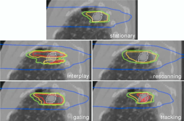
4D RBE-weighted dose distributions for different mitigation techniques. Scanned particle RBE-weighted dose distributions for a lung tumor calculated for different motion mitigation techniques. Isodose lines correspond to 100 % (red), 95 % (yellow), 90 % (green), and 10 % (blue). As described in detail in the Section 7.4.2, rescanning, gating, and tracking result in appropriate CTV (white contour) coverage, while interplay leads to under- as well as overdosage compared to the stationary distribution which is calculated without motion based on the end-exhale 4DCT phase. [Data according to Bert and Rietzel (2007)].
Motion management in ion-beam therapy can be divided into management of interfractional organ motion and intrafractional organ motion. For mitigation of patient movements that are present in addition to organ motion, specific immobilization and correction techniques are used. Some of these techniques rely on imaging data with the patient in the treatment position. Examples are cone-beam CT or orthogonal x-ray imaging. In particular, volumetric data acquisition allows determination of adaptation parameters that ensure appropriate organ positioning for each treatment fraction. Imaging that incorporates the temporal domain has to be used to determine data for mitigation of intrafractional motion, most importantly respiratory motion. One part of imaging is then dedicated to determination of the motion phase, e.g., end-exhale versus end-inhale, while the other part acquires spatial data, i.e., the anatomy at end-exhale. In most volumetric imaging modalities these two parts have to be combined in order to obtain all required information.
Four-dimensional imaging data are used in all steps of the therapy chain. Within treatment planning, one important step is the generation of appropriate margins. In scattered-beam therapy, margins can cover motion-related changes since all parts of the PTV are irradiated simultaneously. Margins can also mitigate the influence of motion in scanned-beam delivery; but for intrafractional organ motion, margins cannot be the only mitigation method because scanned-beam and target-motion interplay can result in RBE-weighted dose errors to the CTV even with an appropriate PTV. The generation of margins for ion beams is not limited to the lateral dimension because of the ion-beam range variation. As for standard treatment planning, the range dependence can be described by translating the anatomical dimensions into water-equivalent lengths by means of HU-lookup tables. This process is field-specific because the patient anatomy in the beam path plays a major role in dose conformation. Thus, margins are also field-specific. Furthermore, margins have to be generated based on data for all possible motion states. Intrafractionally moving targets require incorporation of 4DCT information at least as a benchmark before alternative methods that can be more suitable for the clinic are implemented.
Apart from margin generation, treatment planning involves optimization of parameters for the intrafractional target motion mitigation techniques of gating, beam tracking, and rescanning as well as RBE-weighted dose calculation. RBE-weighted dose calculation can be used in adaptive protocols in which treatment parameters are updated according to the treatment record (imaging data, patient positioning, beam application). For intrafractionally moving targets, 4D RBE-weighted dose calculations are performed that are in principle based on measured parameters of motion trajectory and beam extraction.
The clinically established techniques for treatment of respiration-induced moving tumors such as lung and liver tumors are gating with a scattered beam shaped by absorbers together with abdominal compression, or gating in combination with rescanning for scanned beams. Imaging is used to monitor the motion state of the patient. Alternative mitigation techniques such as beam tracking, a combination of gating, rescanning, and beam tracking, or 4D optimized treatment delivery schemes are currently (2016) in the pre-clinical development stage.
Independent of inter- or intrafractional motion, beam delivery and motion mitigation techniques, the number of uncertainties and thus the need for countermeasures such as employing appropriate margins increases with respect to ion treatment of immobilized tumors. It is thus important to define, validate, and pursue irradiation schemes that incorporate countermeasures for these uncertainties but that also define intervention levels.