
Abstract
Objectives:
Competent velopharyngeal (VP) function is the basis for normal speech. Understanding how VP structure influences the airflow during speech details is essential to the surgical improvement of pharyngoplasty. In this study, we aimed to illuminate the airflow features corresponding to various VP closure states using computed dynamic simulations.
Methods:
Three-dimensional models of the upper airways were established based on computed tomography of 8 volunteers. The velopharyngeal port was simulated by a cylinder. Computational fluid dynamics simulations were applied to illustrate the correlation between the VP port size and the airflow parameters, including the flow velocity, pressure in the velopharyngeal port, as well as the pressure in oral and nasal cavity.
Results:
The airflow dynamics at the velopharynx were maintained in the same velopharyngeal pattern as the area of the velopharyngeal port increased from 0 to 25 mm2. A total of 5 airflow patterns with distinct features were captured, corresponding to adequate closure, adequate/borderline closure (Class I and II), borderline/inadequate closure, and inadequate closure. The maximal orifice area that could be tolerated for adequate VP closure was determined to be 2.01 mm2.
Conclusion:
Different VP functions are of characteristic airflow dynamic features. Computational fluid dynamic simulation is of application potential in individualized VP surgery planning.
Introduction
In the standard velopharyngeal (VP) mechanism, the site and size of the velopharyngeal port are correlated to the speech modulation, in a process called VP closure. 1 Defects in the VP mechanism can lead to velopharyngeal insufficiency (VPI), which is undoubtedly one of the most critical problems after cleft palate repair. Because of the lack of proper contact between the soft palate and the posterior wall of the pharynx, the resulting gap due to inadequate closure of the velopharyngeal port leads to nasal emission and abnormal nasal speech. It is well recognized that the severity of VP insufficiency correlates to the size of this residual gap. Thus, the minimal requirement for a normal VP function has been extensively investigated in the past decades. 2
Protocols of the surgical maneuvers for reconstructing a functional VP closure is based on the VP port for adequate velopharyngeal closure. 2 In previous studies, a pressure-flow technique was established, and the VP orifice areas of 4 conditions of VP closure, including adequate, adequate/borderline, borderline/inadequate, and inadequate, were measured.3-5 The VP orifice area of adequate closure was determined to be less than 5 mm2, and the pressure in the mouth should be between 2943 Pa and 6867 Pa with complete VP closure. 5 These outcomes are the foundations for present surgical management of VPI, such as posterior pharyngeal flap. 6
The accuracy of this pressure-flow measuring model, however, is not guaranteed because of the technological limitations of the past century as the nasal and oral cavities of the model are different from the real upper airway.3-5 Based on present computational and imaging technology, the structure of VP closure could be recapitulated in details.7-15 With the development of computational fluid dynamics (CFD) software, which allows a precise simulation of the airway and enables a detailed prediction of airflow based on 3-dimensional (3D) models derived from image data, 16 we can establish an improved model to recapitulate structure of VP closure and study the correlation between VP orifice and functions.
When adequate VP closure occurs, the pressure in oral cavity will reach the proper magnitude for speech, and no nasal emission should exist. Because there are 4 conditions of VP closure, we hypothesize that the airflow dynamics of different VP conditions should have different patterns. To demonstrate the differences, computational fluid dynamics was applied. In this study, we established airway models of volunteers to investigate the circular patterns of VP closure. We simulated the airflow dynamics in the upper airway by real-time CFD and depicted the airflow velocity, the pressures in both the nasal and oral cavities, in detail.
Materials and methods
Study subjects
This study included 8 adults (3 male and 5 female subjects; 20-31 years) for whom a multislice spiral computed tomography (MSCT) scan was requested for dental or surgical treatment. Clinical examination revealed no notable abnormality in their upper airways. The research protocol was censored and approved by the Ethic Committee of West China Hospital of Stomatology, Sichuan University (Approval No. WCHSIRB-D-2016-084R1). All 8 volunteers provided written informed consent for study participation, and individual participants could not be identified during or after data collection.
MSCT scan and model construction
The MSCT (Philips and Neusoft Medical Systems Co., Ltd., Shenyang, China) scanner was set as follows: voltage value = 120 kVp, current value = 282 mA, exposure time = 26 seconds, slice thickness = 1 mm, slice interval = 1 mm, image index = 0.5 mm, number of slices = 454. During MSCT scanning, subjects kept their mouths closed naturally. DICOM-format images from MSCT were imported into Mimics 15.0 (Mimics, Materialise, Leuven, Belgium). The upper airway models were constructed according to the MSCT data and converted to a smoothed model without losing the patient-specific characteristics of the airway shape. The sinuses were not included because of their negligible participation in VP closure. A cylinder with a radius of 2.82 mm and a height of 4.5 mm was applied to each model to replace the velopharyngeal port in ANSYS Discovery Live (DL) (ANSYS Inc., Canonsburg, Pennsylvania, USA), a CFD software package designed for real-time simulation. The dimensions of the cylinder were chosen based on Warren and Devereux’s 17 pressure-flow model. The inferior area of the cylinder was perpendicular to the posterior wall of the trachea and crossed the anterior edge of the atlas (Figure 1A).
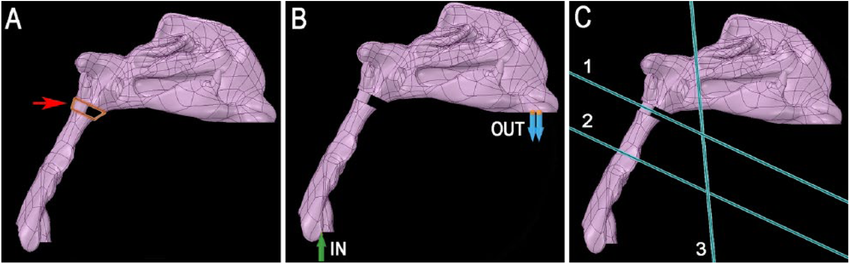
Simulation of velopharyngeal closure using computational fluid dynamics. (A) Geometry of the upper airway constructed using multislice spiral computed tomography (MSCT) scan. The velopharyngeal port was modeled as a cylinder (red arrow). (B) Boundary conditions for airflow simulation. The outlet condition was set at the nostrils, and the inlet condition was set at the cross-section of the trachea at the inferior margin of the C3 vertebra. (C) Three planes for airflow simulation. Plane 1 (P1) crossing the mid-height of the cylinder was used for calculating the air pressure and airflow velocity through the velopharyngeal port; Plane 2 (P2) crossing the inferior edge of the second cervical vertebrae was used for calculating the pressure in the oral cavity; and Plane 3 (P3) at the posterior margin of inferior turbinate was used for calculating the pressure in the nasal cavity.
Circular VP closure pattern simulation and computational fluid dynamics
To simulate the circular pattern of VP closure, the radius of the cylinder was reduced step by step. The CFD simulation was performed under laminar, steady-state airflow at 35°C in the expiratory direction. The nasal walls were assumed to be nonslip and rigid, based on the boundary conditions of a previous airway CFD study. 18 For the outlet condition at the nostrils, the gauge pressure was set to 0 Pa. The expiratory airflow of the inlet condition was set at 250 ml/s at the cross-section of the trachea parallel to the inferior margin of the C3 vertebra 19 (Figure 1B). The time to get enough pressure for normal speech is 0.12 seconds, which is the mean value of the m voiced interval. 3 The fidelity of calculation was set at maximum. Three planes—P1, P2, and P3—were defined in each model to study the airflow dynamics in the velopharyngeal port, the nasal cavity, and the oral cavity, respectively (Figure 1C).
Results
CFD simulation of 8 subjects
After model construction and boundary condition set, the airflow of the upper airway can be simulated by software. The magnitudes of airflow velocity and pressure of target location at different timepoints were calculated automatically. The software restarted the calculation every time the area of the velopharyngeal port changed.
Since 120 ms maintenance of oral pressure is the minimum requirement for clear speech, 3 the air velocity and pressure in each simulation were recorded at 120 ms. The airflow velocity and pressure through the velopharyngeal port and the pressure in oral and nasal cavities changed as the area of the velopharyngeal port increased from 0 to 25 mm2 (Figure 2). For each of the 8 subjects, the air velocity at the velopharyngeal port remained 0 when the area was below 5 mm2 but increased sharply at a critical threshold and reached the maximal value when the port was between 5 mm2 and 10 mm2 before decreasing to a relatively stable level around 5 m/s when the VP port was larger than 15 mm2 (Figure 2A).
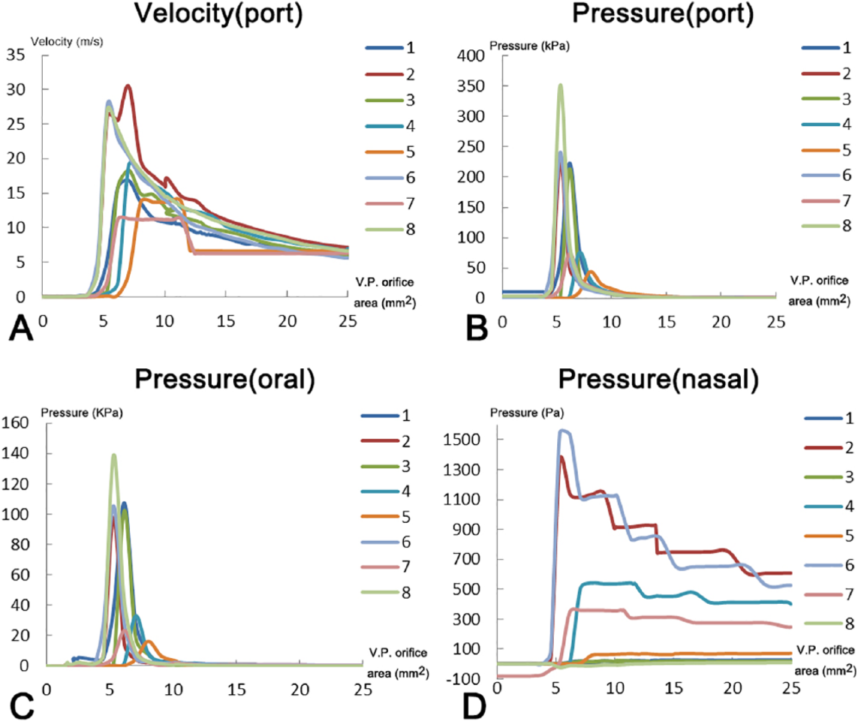
Airflow velocity and pressure in each simulation. (A) Airflow velocity at the velopharyngeal port. (B-D) Air pressures at the velopharyngeal port, oral cavity, and nasal cavity, respectively. Data were recorded at 120 ms of the simulation.
Similarly, the pressures at the velopharyngeal port (Figure 2B), oral cavity (Figure 2C), and nasal cavity (Figure 2D) all reached the maximum when the velopharyngeal port was around 5 mm2. The pressures at the velopharyngeal port and the oral cavity dropped drastically after reaching the maximum. In contrast, the pressure at the nasal cavity decreased more gradually and was maintained at a low level above 0 Pa.
Airflow patterns change according to the size of the velopharyngeal port
When the software was doing the calculation, the curves of the airflow velocity and pressure with time were shown. These simulation outcomes were influenced by the conditions of the airway structure. Therefore, as we changed the structure, the curves can demonstrate the airflow dynamic changes. Based on the simulation outcomes generated by the software, we can study the characteristics of VP closure (Figure 3, left and middle column). The animation could visually present the airflow in the structure, for example, airflow emission (Figure 3, right column; and supplemental videos in the online version of the article).
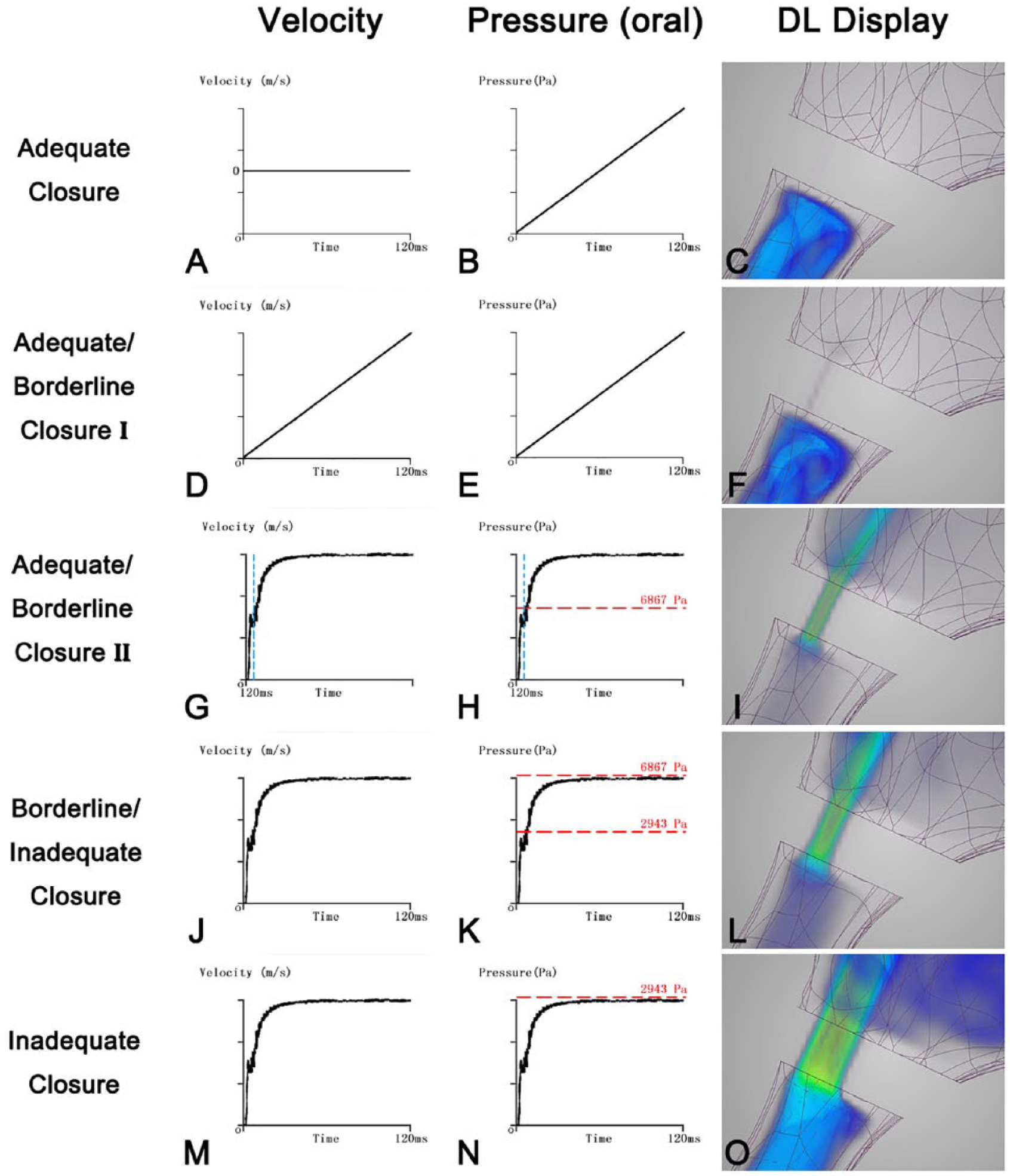
Airflow velocity and pressure patterns under different velopharyngeal closure conditions. (A, D, G, J, M) Changes in airflow velocity through the velopharyngeal port and (B, E, H, K, N) pressure in the oral cavity during 120 ms of simulation. The patterns of airflow in the model were from subject No. 5. (C) R (radius of the cylinder) = 0.5 mm. (F) R = 1.00 mm. (I) R = 1.5 mm. (L) R = 2.00 mm. (O) R = 2.82 mm.
As the area of the VP port increased, 4 conditions with 5 patterns of airflow dynamics were observed (Figure 3). Airflow velocity through the velopharyngeal port represents nasal emission, and pressure in the oral cavity serves as the oral pressure before the speech. When the oral pressure reaches 2943 Pa, which is the minimum requirement for typical speech, it is no longer considered inadequate closure. 5
When the area of VP orifice started to increase from 0 mm2, we observed the first pattern, in which airflow velocity through the velopharyngeal port remained 0 m/s for the whole duration of the simulation (Figure 3A), indicating that there was no nasal emission. Meanwhile, the pressure in the oral cavity increased with time (Figure 3B). The oral pressure, however, sometimes could not reach 2943 Pa within 120 ms due to the limitation of the software. The reason for this phenomenon is that as the closure became more complete, the fluid resistance in the cavity would also increase and eventually influence the present outcome. This first pattern is considered adequate closure (Figure 3C).
As the area continued to increase, 4 more patterns of airflow dynamics were observed. In the second observed pattern, the equilibrium between nasopharynx and oropharynx was not established. Airflow velocity through the velopharyngeal port and pressure in the oral cavity increased linearly with time (Figures 3D, 3E), and nasal emission started to be observed in this condition. The oral pressure in a few subjects, however, would not reach 2943 Pa in 120 ms; it was due to the same reason as discussed in adequate closure. This pattern represents the first type of adequate/borderline closure (Class I) (Figure 3F).
In the third pattern, airflow velocity through the velopharyngeal port and pressure in the oral cavity reached a balance, which meant that the equilibrium between nasopharynx and oropharynx was established (Figures 3G, 3H), and nasal emission was observed. In this condition, the pressure in the oral cavity would reach 6867 Pa and more, which was entirely appropriate for normal speech. This pattern is the second type of adequate/borderline closure (Class II) (Figure 3I).
In the fourth observed pattern, airflow velocity through the velopharyngeal port and pressure in oral cavity also reached a balance, indicating that equilibrium was established and nasal emission also existed (Figure 3JK), as in the adequate/borderline closure (Class II). However, in this condition, the pressure in the oral cavity could reach 2943 Pa but not 6867 Pa. This represents borderline/inadequate closure (Figure 3L).
In the last observed pattern, the equilibrium between nasopharynx and oropharynx was again established with nasal emission (Figures 3M, 3N). However, the pressure in the oral cavity would never reach 2943 Pa, which is not sufficient for normal speech, indicating inadequate closure (Figure 3O).
Outcomes of the airflow patterns in different conditions generated by ANSYS Discovery Live are shown in Figures 3C, 3F, 3I, 3L, and 3O. Since our study was a real-time, transient simulation in which the scale bar was changing with time, the scale bar could not be fixed and thus is not shown. The real-time simulations were captured in Supplemental Videos 1 to 5 (available in the online version of the article) to demonstrate the entire process of airflow dynamics.
Areas of VP orifice in different conditions
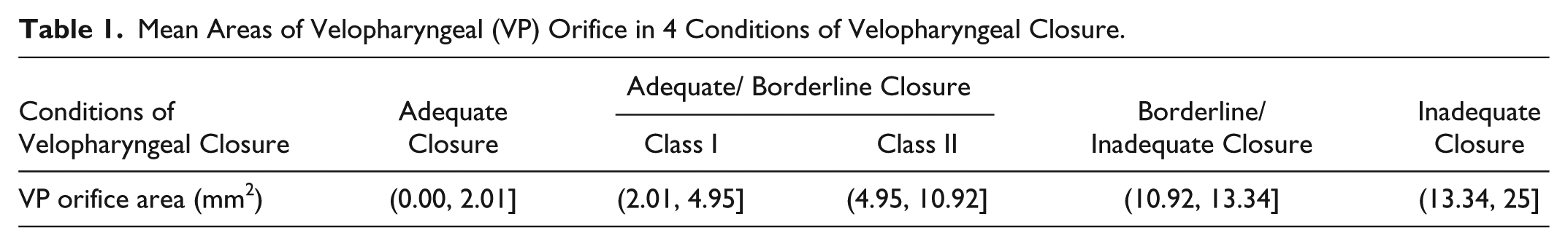
Based on the airflow dynamics observed in Figure 3, we calculated the areas threshold associated with each of the 5 patterns (Table 1). The lower and upper limits in each condition are the mean values of the subjects. The maximal orifice area for adequate closure was determined to be 2.01 mm2.
Mean Areas of Velopharyngeal (VP) Orifice in 4 Conditions of Velopharyngeal Closure.
Discussion
For better outcomes of postoperative speech restoration of cleft palate, it is essential to understand the correlation between the velopharyngeal port and airflow dynamics. Using CFD, our study demonstrated the different characteristics of airflow patterns in 4 distinct conditions of velopharyngeal closure.
Insufficient VP closure is the result of velopharyngeal dysfunction. Its effects on speech have been well studied in the past century, and there were some devices designed to measure oral pressure and detect nasal emission.5,20,21 Whether they are clinical tools or computational simulations, the accuracy cannot be guaranteed because of the technical limitations. In the early 1980s, Warren and colleagues3-5 demonstrated the change in size of the VP orifice on airflow dynamics under 4 conditions of VP closure. These studies helped elucidate the closure conditions, but the limitations were obvious: The geometry of their simulation was not realistic enough to capture the real human airway, and such bias could lead to the uncertain surgical outcomes.
In our study, real-time CFD was used to simulate the dynamic process of different conditions of VP closure and investigate the characteristics of airflow in the upper airway. In this study, MSCT scans of volunteers were acquired to represent the realistic human upper airway, in which the velopharyngeal port was portrayed as a cylinder. 17 By changing the radius of the cylinder, the change of the cross-sectional area represented different sizes of the VP orifice.
Simulations of randomly selected subjects with varying VP orifices were analyzed, and the same patterns of airflow were observed (Figure 2). As the area of VP orifice decreased from 25 mm2 to 0 mm2, airflow velocity through the velopharyngeal port became higher and reached the maximum in adequate/borderline closure and dropped to 0 when there was an adequate closure. The pressure in the oral cavity exhibited almost the same patterns as the airflow velocity.
One of our objectives was to find a way to distinguish the different states of VP closure and summarize the features of Warren’s3-5 4 conditions by CFD. According to the results of airflow velocity and pressure patterns, different states of VP closure can finally be categorized in these 4 conditions (Figure 3), which exhibit 5 airflow patterns:
adequate closure: airflow velocity through the velopharyngeal port remained zero at all times;
adequate/borderline closure: (a) Class I: airflow velocity through the velopharyngeal port and pressure in the oral cavity increased steadily with time and (b) Class II: airflow velocity through the velopharyngeal port and pressure in the oral cavity stayed stable, and the pressure in the oral cavity could exceed 6867 Pa;
borderline/inadequate closure: airflow velocity through the velopharyngeal port and pressure in the oral cavity stayed stable, and the pressure in the oral cavity was between 2943 to 6867 Pa;
inadequate closure: airflow velocity through the velopharyngeal port and pressure in the oral cavity stayed stable, and the pressure in the oral cavity was less than 2943 Pa.
The real-time CFD simulations demonstrated inherent differences among these 4 conditions. In the adequate closure, there was no airflow escaping from the cylinder, indicating no nasal emission and complete VP closure (Figure 3C). In the adequate/borderline closure Class I, there was slight nasal emission, but most air was gathered in the oral cavity (Figure 3F). In Class II, however, significant nasal emission existed, as found in borderline/inadequate closure and inadequate closure conditions (Figures 3I, 3L, 3O). These exciting findings have clinical significance, suggesting that in the presence of a VP orifice, as long as it is small enough, there is a possibility of zero nasal emission.
Another objective of this study was to revise the VP orifice areas in Warren and colleagues’3-5 4 conditions of VP closure. Comparing with the results obtained by Warren, 5 the orifice area for adequate closure was changed from less than 5.00 mm2 to less than 2.01 mm2. The range of adequate/borderline closure was defined as 2.01 mm2 to 10.92 mm2, which included the former results of 5.00 mm2 to 9.00 mm2. However, this adequate/borderline closure could be divided into 2 classes based on the observed patterns. The area of the VP orifice ranged from 2.01 mm2 to 4.95 mm2 in Class I and from 4.95 mm2 to 10.92 mm2 in Class II. The orifice in borderline/inadequate closure was between 10.92 mm2 and 13.34 mm2 and between 13.34 mm2 and 25 mm2 in inadequate closure. The most significant change was that when the pressure in the oral cavity cannot meet the requirement for normal speech, the VP orifice should be greater than 13.34 mm2 in our study, versus 20 mm2 in Warren’s study. 5 Our study was based on the pressure required for normal speech. 5 Thus, it was a different design from former studies, in which the pressure was the experimental result. This study design could generate more physiologically relevant results and provide new insights.
Selection of different surgical procedures, which depends on the condition of the preoperative VP closure status, will affect the clinical outcome. Our work defined the airflow dynamics in these 4 conditions of VP closure. Our study also demonstrated that the requirement of VP orifice area was different from patient to patient because of their different anatomy. With the fast and convenient real-time CFD simulation, it is possible to construct and analyze the upper airway of each patient by CFD to better understand the patient’s condition and reconstruct the appropriate VP orifice when performing secondary cleft palate repair.
Our study also has several limitations. Although our geometry and results are more accurate than previous reports, the cylinder representing the velopharyngeal port for the circular pattern was still an oversimplified model. To get a continuous change in the 3D model, the simplification of some parts of the model is necessary because of the limitation of the reconstructive techniques, which remain somewhat different from the real situation. The next limitation in our model is that the expiration rate was set as constant since the whole simulation only lasted 120 ms. These differences can impact airflow and change the simulation results. Future investigation should be focused on a more accurate airway model that allows continuous changes in VP size and nonsteady expiration rate.
Conclusions
In this study, real-time CFD simulation was used to depict the correlation between the area of the velopharyngeal port and the airflow dynamics. The minimal requirement of VP orifice area for speech has been demonstrated, and this technology can potentially be applied in surgical design for each patient.
Footnotes
Declaration of Conflicting Interests
The author(s) declared no potential conflicts of interest with respect to the research, authorship, and/or publication of this article.
Funding
The author(s) disclosed receipt of the following financial support for the research, authorship, and/or publication of this article: This work was supported by the Sichuan Science & Technology Program grant to J.L. (2017RZ0036).
Supplemental Material
Supplemental material for this article is available online.
References
Supplementary Material
Please find the following supplemental material available below.
For Open Access articles published under a Creative Commons License, all supplemental material carries the same license as the article it is associated with.
For non-Open Access articles published, all supplemental material carries a non-exclusive license, and permission requests for re-use of supplemental material or any part of supplemental material shall be sent directly to the copyright owner as specified in the copyright notice associated with the article.