
Abstract
A nondispersive infrared gas analyzer was demonstrated for investigating metal alkylamide precursor delivery for microelectronics vapor deposition processes. The nondispersive infrared analyzer was designed to simultaneously measure the partial pressure of pentakis(dimethylamido) tantalum, a metal precursor employed in high volume manufacturing vapor deposition processes to deposit tantalum nitride, and dimethylamine, the primary decomposition product of pentakis(dimethylamido) tantalum at typical delivery conditions for these applications. This sensor was based on direct absorption of pentakis(dimethylamido) tantalum and dimethylamine in the fingerprint spectral region. The nondispersive infrared analyzer optical response was calibrated by measuring absorbance as a function of dimethylamine and pentakis(dimethylamido) tantalum density. The difference between the mass of material removed from the ampoule during flow tests as measured gravimetrically and as determined optically, by calculating flow rates from the nondispersive infrared analyzer measurements, was only ≈2 %. The minimum detectable molecular densities for pentakis(dimethylamido) tantalum and dimethylamine were ≈2 × 1013 cm−3 and ≈5 × 1014 cm−3, respectively (with no signal averaging and for a sampling rate of 200 Hz), and the corresponding partial pressures were ≈0.1 Pa and ≈2 Pa for pentakis(dimethylamido) tantalum and dimethylamine, respectively (for an optical flow cell temperature of 93 ℃). Pentakis(dimethylamido) tantalum could be detected at all conditions of this investigation and likely the majority of conditions relevant to high volume manufacturing tantalum nitride deposition. Dimethylamine was not detected at all conditions in this study, because of a lower nondispersive infrared analyzer sensitivity to dimethylamine compared to pentakis(dimethylamido) tantalum and because conditions of this study were selected to minimize DMA production. While this nondispersive infrared gas analyzer was specifically developed for pentakis(dimethylamido) tantalum and dimethylamine, it is suitable for characterizing the vapor delivery of other metal alkylamide precursors and the corresponding amine decomposition products, although in the case of some metal alkylamides a different bandpass filter would be required.
Keywords
Introduction
Metal alkylamide compounds are widely utilized in chemical vapor deposition (CVD) and atomic layer deposition (ALD) processes as metal precursors for depositing thin films of metal oxides, silicates, and nitrides, 1 materials having applications in microelectronics as diffusion barriers, metal gates, gate dielectrics and capacitor dielectrics, as well as in other areas, e.g., catalysis, wear-resistant coatings, optical coatings, and sensors. In the area of microelectronics, pentakis(dimethylamido) tantalum (PDMAT), Ta[N(CH3)2]5, has been employed as the tantalum precursor for tantalum nitride2–6 and tantalum oxide7–10 films deposited both by CVD2,10 and ALD3–9 processes. In fact, PDMAT is employed in high volume manufacturing (HVM) ALD processes for depositing TaN copper diffusion barriers. Furthermore, as these HVM ALD processes continue to evolve, tighter control of the precursor flux to the deposition surface is required to better control film thickness and properties, thereby maintaining device yield. (Although the deposition rate in an ideal ALD process is independent of precursor flux for a precursor dose sufficient to saturate all surface reaction sites, 1 HVM ALD processes are sometimes operated under conditions in which CVD mechanisms occur resulting in a dependence of deposition rate on precursor flux.) Hence, PDMAT and factors affecting PDMAT delivery are of interest.
The PDMAT vapor is generally entrained in an inert carrier gas for delivery to the growth surface from an ampoule located at or near the deposition tool. PDMAT is a low-volatility solid at practical delivery temperatures, with a vapor pressure of 6.7 Pa at 55 ℃ 11 and a melting point greater than 100 ℃. 12 Reproducibly delivering solid precursors can be difficult compared to gas or liquid precursors. This difficulty can be due to factors such as changes in surface area, limited mass transport processes in ampoules appropriate for solids, and cooling due to sublimation. 13 In addition, PDMAT is generally delivered at elevated temperatures to compensate for low volatility and to deliver more precursor to the deposition surface. However, metal alkylamide compounds can pyrolyze at elevated temperatures to produce the secondary amine corresponding to the hydrogenated ligand of the parent molecule.14–18 In the case of PDMAT, the amine is dimethylamine (DMA), (CH3)2NH. The presence of the amine can potentially impact deposition processes via (1) perturbation of the metal alkylamide flux through perturbations of the system pressure and (2) inhibition of reactions in which DMA is a product, e.g., transamination reactions with ammonia. 19 Hence, a better understanding of the factors influencing PDMAT delivery from an ampoule as well as DMA evolution could facilitate improvement of TaN ALD methods. This is the motivation for the work described in this report: the development of a nondispersive infrared (NDIR) gas analyzer capable of measuring the PDMAT and DMA partial pressure in a carrier gas delivered from commercial ampoules under conditions relevant to HVM TaN ALD processes.
The specific conditions for HVM TaN ALD processes obviously vary, and, therefore, any diagnostic utilized for PDMAT delivery studies should be capable of operating over a range of conditions. For many HVM TaN ALD processes, the carrier gas flow rate ranges up to ≈1.50 L/min at standard temperature and pressure (STP), defined as 0 ℃ and 101.33 kPa, while the ampoule pressure ranges up to ≈6.7 kPa (≈50 Torr). The ampoule temperature ranges up to 80 ℃. PDMAT injection times are on the order of seconds. The requirement to operate under these conditions can be challenging for many techniques that have been utilized for in situ metalorganic precursor measurements, as detailed previously. 20 Acoustic methods have been widely employed for CVD processes but tend to be limited to pressures above ≈6.7 kPa, which makes them unsuitable for ALD processes. Ultraviolet absorption-based methods employ a radiation source capable of photolyzing metalorganic precursors, which is of concern for metal alkylamide delivery studies. Fourier transform infrared (FT-IR) spectroscopy-based methods tend to operate with limited data acquisition rates, which is of concern with HVM ALD processes where cycle times can be short. IR laser-based methods sometimes exhibit experimental instability over long timescales, which is of concern for long-duration measurements associated with ampoule fill lifetime studies. NDIR gas analyzers have been shown to be capable of providing rapid, stable precursor concentration measurements for metalorganic compounds; however, these capabilities have been demonstrated only for a few compounds and in sometimes limited investigations.20–26 Of these demonstrated NDIR gas analyzers, a number operate based on isolating absorption modes in the C–H stretching spectral region.21,25,26 Since both PDMAT and DMA absorb in this spectral region,27–32 the potential for strong spectral interference between the two species is high in this region, complicating data analysis. To reduce the potential for interference between a metal alkylamide and the corresponding amine decomposition product, NDIR gas analyzers designed to monitor both species can be based on isolating absorption modes in the fingerprint spectral region. Such an approach has been demonstrated in two previous reports involving tetrakis(dimethylamido) titanium and DMA 24 and tetrakis(ethylmethylamido) hafnium and methylethylamine. 23 However, in these reports, only the absorbance of the respective species was reported, i.e., the optical response of these NDIR gas analyzers was not calibrated. To date, no NDIR gas analyzer has been reported for simultaneously measuring the partial pressure of both a metal alkylamide compound and the corresponding amine decomposition product during metal alkylamide delivery processes.
The objective of this report is to describe the performance of a NDIR gas analyzer designed to measure the partial pressure of PDMAT and DMA under conditions relevant to HVM TaN ALD processes. The NDIR gas analyzer was based on direct absorption measurement of PDMAT vapor and DMA in the fingerprint spectral region. The analyzer utilized a broadband infrared filament source, an optical chopper to modulate the source, a 10.6 μm center-wavelength beam splitter, a 10.56 μm and 14.03 μm center-wavelength bandpass filter for PDMAT and DMA, respectively, and two mercury cadmium telluride (MCT) detectors. The NDIR analyzer optical response was calibrated by measuring absorbance as a function of density during DMA and PDMAT injection. The calibration method was validated by comparing the mass of PDMAT and DMA removed from the ampoule during carrier gas flow, as determined by calculating PDMAT and DMA flow rate from the NDIR analyzer measurements, to the mass determined gravimetrically.
Experimental Procedure
Materials
Microelectronics-grade PDMAT (EMD Performance Materials a ) was obtained in stainless steel containers and employed as received without further purification. For flow tests, a ≈1.5 L vapor draw ampoule contained a starting mass of 200 g. (In this work, a “vapor draw ampoule” refers to a vessel through which carrier gas flows but which has no dip tube: the gas in and gas out ports open directly into the ampoule head space.) The ampoule mass was recorded before and after flow tests using a top-loading precision balance with a manufacturer-specified repeatability standard deviation of less than 0.01 g. For reference spectrum measurement, a ≈0.05 L ampoule contained a starting PDMAT mass of 5 g. Anhydrous DMA (>99 % purity, Sigma-Aldrich) was received as a liquefied gas and transferred to an electropolished stainless steel finger to determine NDIR gas analyzer sensitivity. Prior to this determination, the finger was degassed in the following manner. The DMA-containing portion of the finger was immersed in an acetone/dry ice bath, the finger head space was evacuated with a vacuum pump, and then the finger was thawed. This process was repeated multiple times. Ultra-high-purity grade argon (99.999 % pure) that was further purified with a point-of-use purifier was used as the carrier gas for flow measurements.
Measurement of PDMAT Reference, DMA Reference, and Filter Spectra
Figure 1 shows the (a) PDMAT and DMA molar absorptivity and (b) PDMAT and DMA molar absorptivity (shown in blue in Fig. 1b) in the fingerprint region of the spectra compared to the bandpass filter transmittance spectra (shown in red in Fig. 1b). The DMA molar absorptivity was determined previously with a commercial FT-IR spectrometer at 1 cm−1 spectral resolution using a liquid nitrogen-cooled wideband mercury cadmium telluride (MCT) detector.
33
The PDMAT molar absorptivity was determined in a similar manner with a 12.4 cm path length vacuum optical cell and a commercial FT-IR spectrometer at 1 cm−1 spectral resolution using a deuterated triglycine sulfate detector (DTGS) and using a heated capacitance diaphragm gauge (CDG) with a 1 kPa full scale range to measure the optical cell pressure. The PDMAT spectrum was not corrected for sample emissivity. The transmittance spectra of the bandpass filters were measured using a DTGS. In Fig. 1, The PDMAT and DMA spectra both exhibit relatively intense features in the fingerprint region below ≈1500 cm−1 and C–H stretching region from ≈2700 cm−1 to ≈3100 cm−1, in agreement with previous reports for PDMAT27–29 and DMA.30–32 In both spectral regions, the molar absorptivity of PDMAT features tends to be larger than those of DMA. The higher molar absorptivity is an obvious advantage for maximizing the PDMAT detection limit; however, the lower DMA molar absorptivity is a disadvantage when trying to account for potential contributions from DMA to the measured pressure. The DMA feature observed at ≈735 cm−1, attributed to the N–H bend,30,31 is spectrally resolved and reasonably intense (see Fig. 1b). Hence, this feature was selected to monitor DMA using a filter with a center wavelength of ≈14.03 μm (713 cm−1), a full width at half maximum (FWHM) of ≈0.97 μm, and a peak transmission of ≈76 %.. This feature is also obvious in the PDMAT spectrum and is attributed to the presence of DMA resulting from PDMAT pyrolysis (the ampoule heater temperature was ≈69 ℃). Despite prolonged pumping on the PDMAT ampoule prior to each measurement, the DMA feature was always observed under the conditions employed in this work. The PDMAT feature observed at ≈946 cm−1, attributed to the NC2 symmetric stretching mode
27
or this mode coupled with the Ta–N stretching mode,
28
is intense and, therefore this feature was selected to monitor PDMAT, despite the potential for a weak interference between DMA and PDMAT. A filter with a center wavelength of ≈10.56 μm (947 cm−1), a FWHM of ≈0.24 μm, and a peak transmission of ≈86 % was used to isolate this feature. When determining the PDMAT density for the molar absorptivity calculation, the contribution to the measured pressure from DMA was removed by using the intensity of the ≈735 cm−1 feature to calculate the corresponding DMA density from the molar absorptivity.
The (a) PDMAT and DMA molar absorptivity and (b) PDMAT and DMA molar absorptivity (shown in blue in Fig. 1b) in the fingerprint region of the spectra compared to the bandpass filter transmittance spectra (shown in red in Fig. 1b). The DMA molar absorptivity is scaled by a factor of five in each figure.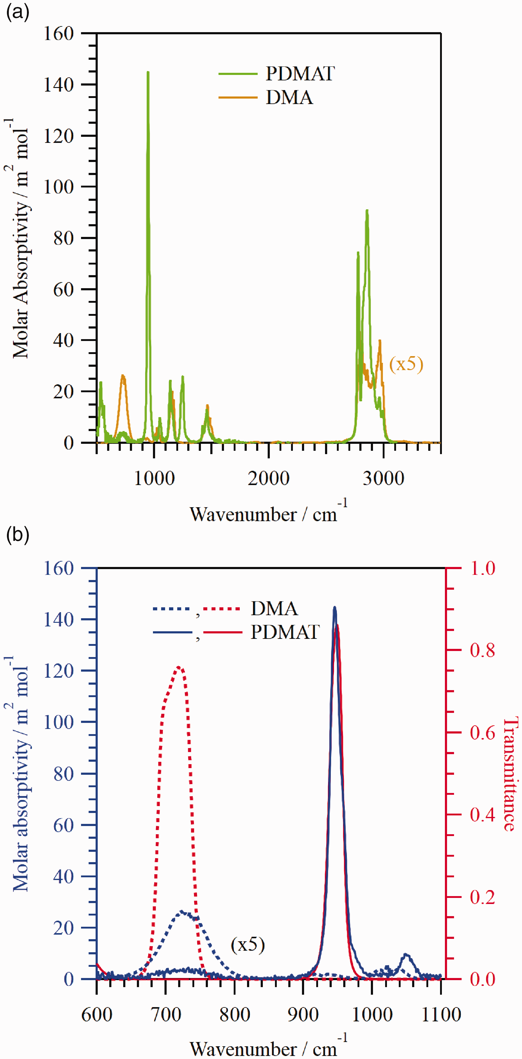
NDIR Gas Analyzer Optical System and Gas Flow System
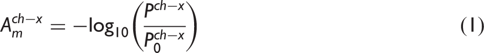
Figure 2 shows a schematic of the apparatus used for this investigation which can be described in two parts: The NDIR gas analyzer system (shown in blue in Fig. 2) and the gas flow system (shown in black). The NDIR gas analyzer measurements were performed using a wire filament source, which operated ≈1323 K and used ≈11 W of power. The source output was amplitude modulated at 670 Hz using an optical chopper. Five 25.4 mm diameter, plano–convex, zinc selenide lenses with anti-reflection coatings optimized for 8 μm to 12 μm were used to collect radiation from the source (100 mm focal length), to transfer radiation through the optical cell, and to focus radiation onto one of two detectors (25.4 mm focal length at each detector). To focus radiation through the optical cell, a pair of 150 mm focal length and 100 mm focal length lenses was used for calibration measurements and flow measurements, respectively. The radiation exiting the cell was passed through a pair of long pass filters with a specified 5 % transmission wavelength of 7.3 μm. (The long pass filters were used to further reduce radiation incident on the detectors, particularly at wavelengths shorter than the bandpass filter passband where the source irradiance was greater and some bandpass filters exhibited higher transmission.) The radiation was subsequently split using a ZnSe beam splitter that was coated for operation at a 45° angle of incidence and a wavelength of 10.6 μm. The radiation transmitted through the beam splitter, referred to as the PDMAT channel, was directed through the 10.56 μm center wavelength filter, through a 850 μm mesh (No. 20 alternative sieve designation) woven wire cloth, and through a lens on to a liquid nitrogen-cooled MCT detector. This detector had a specified peak detectivity (at 1 kHz), responsivity, and wavelength of ≈5.0 × 1010 cm·Hz1/2·W−1, ≈2.5 ×10⁴ V/W, and ≈11.7 μm, respectively. The radiation reflected from the beam splitter, referred to as the DMA channel, was directed through the 14.03 μm center wavelength filter and through a lens on to a liquid nitrogen-cooled MCT detector. This detector had a specified peak detectivity (at 1 kHz), responsivity, and wavelength of ≈6.9 × 1010 cm·Hz1/2·W−1, ≈1.6 × 10⁴ V/W, and ≈12.6 μm, respectively. The voltage output from each detector was amplified by a factor of 100 using a preamplifier and was filtered using a lock-in amplifier (10 ms time constant), the analog output of which (16-bit, ± 10 V digital-to-analog converter (DAC) output) was digitized at 200 Hz or 1000 Hz using a 24-bit data acquisition board. The measured (decadic) absorbance on channel x, Schematic diagram of the experimental configuration used to perform the measurements described in this work with the NDIR gas analyzer and the flow system shown in blue and black, respectively. MFC: mass flow controller; CDG1 and CDG2: capacitance diaphragm gauges; PV1, PV2, and PV3: pneumatically actuated diaphragm valves; MV1 and MV2: manual valves; FC: optical flow cell; ZS1 and ZS2: zinc selenide windows; TV: manual throttle valve; IR: IR source; OC: optical chopper; L1, L2, L3, L4, and L5: zinc selenide lenses; LP: long pass filter; BS: beam splitter; BP1: PDMAT bandpass filter; BP2: DMA bandpass filter; MCT1: PDMAT MCT detector; MCT2: DMA MCT detector.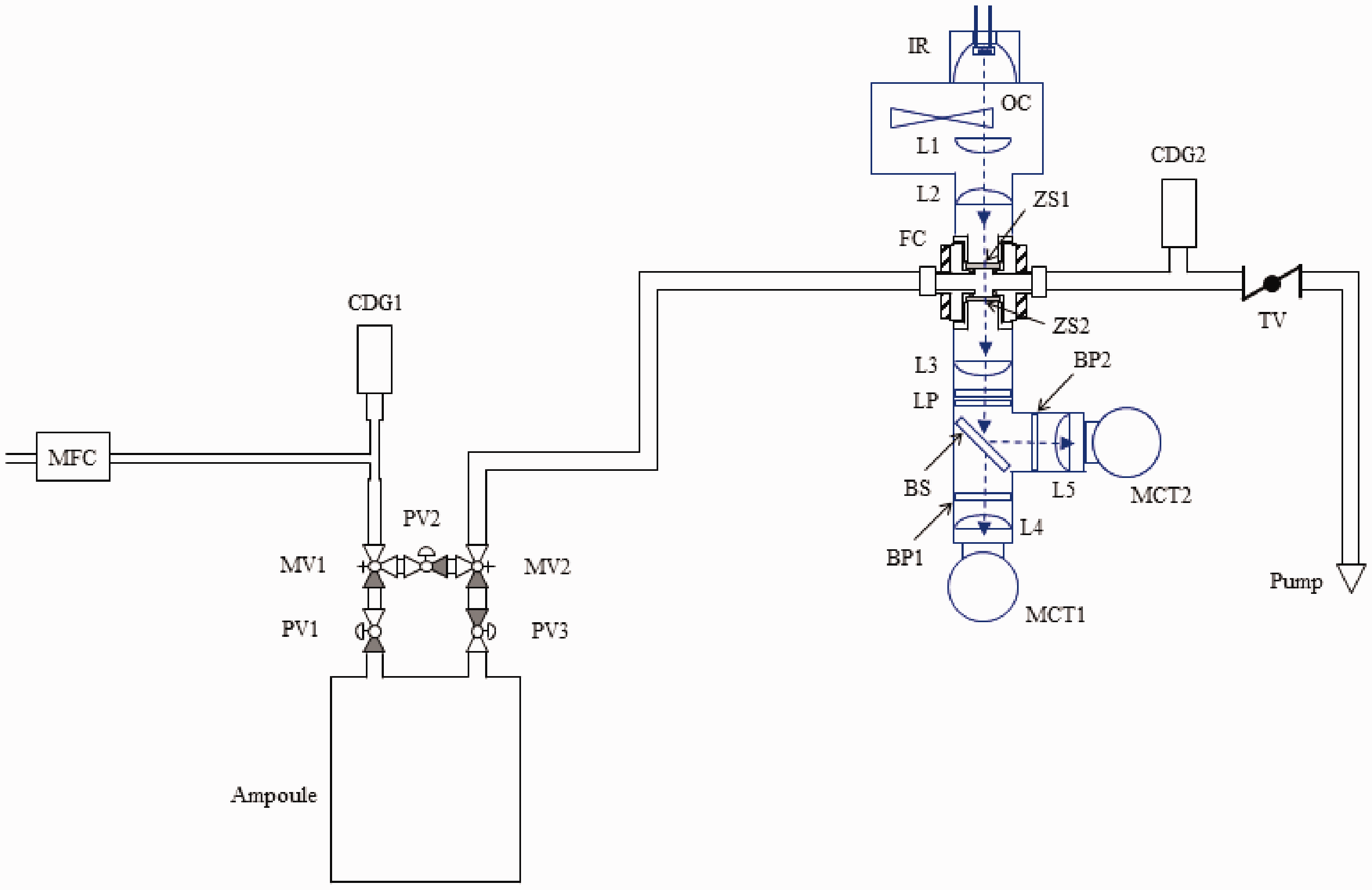


The characteristics of the flow system shown in Fig. 2 have been previously reported 34 and will only be described briefly here. The PDMAT ampoule shown was configured with a five-valve cluster that includes three pneumatic two-port valves (PV1, PV2, and PV3) and two manual three-port valves (MV1 and MV2). An in-line optical flow cell (FC) was used to provide optical access for the NDIR gas analyzer. Measurements were made in a single-pass and the nominal optical path length between the flow cell interior window surfaces was 15.2 mm. Argon flow was controlled by a mass flow controller and the flow rates employed in this work ranged from 0.25 L/min to 1.50 L/min at STP. In subsequent discussions, flow rates are referenced to STP unless otherwise noted. Pressure was measured using capacitance diaphragm gauges upstream of the ampoule (CDG1) and downstream of the flow cell (CDG2). The conductance of the flow system was controlled using a manual throttle valve (TV). Flow in the system was initiated in the purge configuration (with no flow through the ampoule) by opening the pneumatic valve PV2, with PV1 and PV3 being closed (MV1 and MV2 were open for all measurements), setting the MFC to the desired flow rate, and adjusting TV to obtain the desired pressure in the flow cell, as measured on CDG2. The injection configuration (the configuration used to inject PDMAT) involved directing carrier gas through the ampoule, and in this configuration, PV2 was closed, with PV1 and PV3 being open. All surfaces from CDG1 to TV were heated to avoid precursor condensation. The ampoule was encased in an aluminum jacket with the sides and bottom being actively heated with flexible strip heaters and the top plate being passively heated. Mineral-insulated, metal-sheathed type K thermocouples were used to measure the temperature for active temperature control. The estimated temperature accuracy was ± 2.2 ℃ at 250 ℃ with k = 2 (k being a numerical factor corresponding to the desired confidence level 35 ), based on manufacturer's specifications. The temperature setpoint for the valve cluster and inlet line was 5 ℃ above the respective ampoule jacket heater setpoint and that of the rest of the measurement system was 93 ℃.
NDIR Gas Analyzer Response Calibration
The NDIR gas analyzer optical response as a function of analyte pressure was determined separately from the flow cell using a 12.693 cm long path length vacuum optical cell (nominally identical to that used to measure the reference spectra 33 ) configured with a 1.33 kPa full scale range CDG (with a 100 ℃ heater set point).
The optical response to DMA was determined by injecting DMA into the optical cell and then repeatedly pumping on the cell for time periods ranging from 0.1 s to 2.0 s to vary the DMA density in the optical path. The following expressions were fit to the DMA absorbance versus density data from both channels using linear regression
The (a) 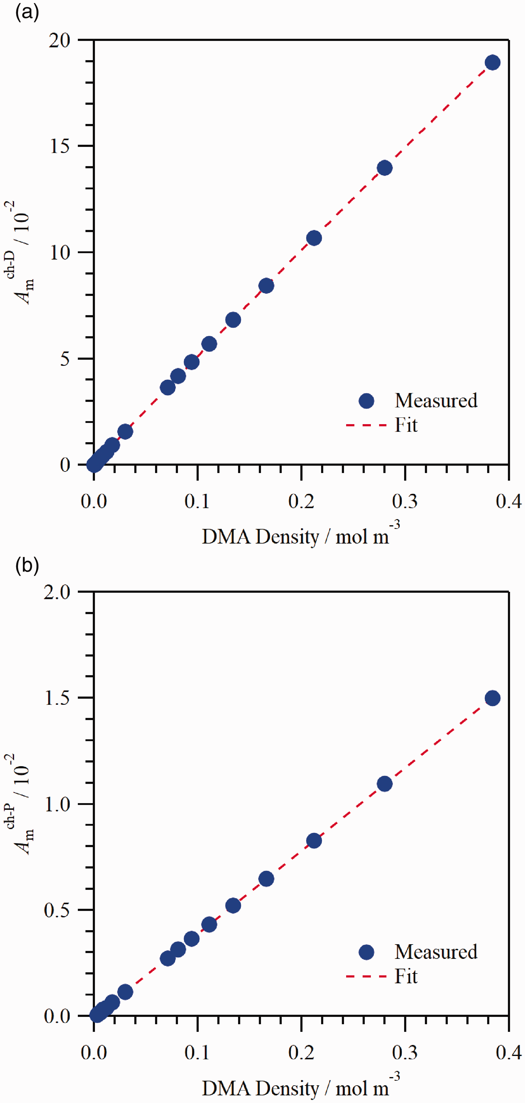


Determining the optical response to PDMAT is complicated by the presence of DMA during PDMAT injection. The PDMAT density, CP , was taken as The measured 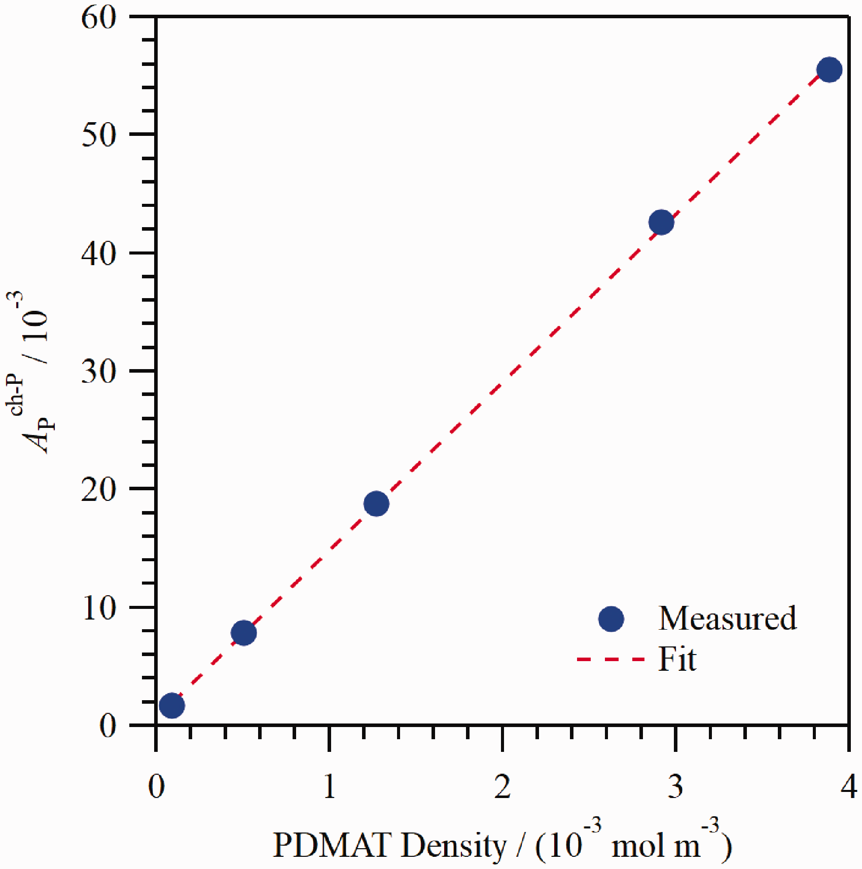


The calibration coefficients used to define the dependence of absorbance on molecular density for PDMAT and DMA in the flow cell.
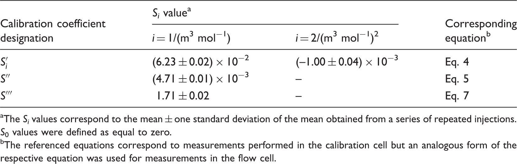
The S i values correspond to the mean ± one standard deviation of the mean obtained from a series of repeated injections. S0 values were defined as equal to zero.
The referenced equations correspond to measurements performed in the calibration cell but an analogous form of the respective equation was used for measurements in the flow cell.
As discussed previously, 3s
bl
= 6.0 × 10⁻⁵ for the PDMAT channel. The value of r
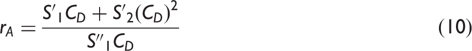
A
ranges from 13.2 to 12.3 as DMA density increases from 1 × 10⁻⁴ m−3 to 0.5 m−3. This corresponds to
Results and Discussion
Figure 5 shows the (a) PDMAT and (b) DMA absorbance and corresponding partial pressure for five 45 s PDMAT injections at ampoule jacket heater temperatures from 60 ℃ to 78 ℃. The carrier gas flow rate was 1 L/min and the pressure at CDG2 was ≈5.2 kPa. The PDMAT absorbance (partial pressure) decreases from a maximum early in the injection to a steady-state value after ≈30 s for all injections. This decrease in PDMAT partial pressure upon initiation of flow through the ampoule is attributed to incomplete saturation of the carrier gas (i.e., the mass transfer processes in the ampoule are insufficient to permit saturation of the carrier gas) and cooling of the precursor due to sublimation (i.e., cooling reduces the precursor temperature). At a given time, the absorbance decreases with decreasing ampoule temperature as the vapor pressure decreases with decreasing precursor temperature. The DMA absorbance (partial pressure) exhibits similar behavior to that of PDMAT. However, the DMA data exhibit a significantly lower SNR than the PDMAT data: the signal levels are comparable to the output resolution of the lock-in amplifier DAC and there is an apparent drift in the detector output. As discussed previously, the minimum detectable absorbance on the PDMAT and DMA channel was ≈6 × 10⁻⁵ and ≈5 × 10⁻⁵, respectively. In Fig. 5, the PDMAT absorbance ranges from a maximum of ≈1.2 × 10⁻² at the 78 ℃ ampoule temperature to a minimum absorbance of ≈1.1 × 10⁻³ at 60 ℃, i.e., well above the 6 × 10⁻⁵ level for all conditions. However, the maximum DMA absorbance reaches a maximum of only ≈2.8 × 10⁻⁴ at the 78 ℃ ampoule temperature, i.e., the DMA absorbance is comparable to or below the 5 × 10⁻⁵ level for the duration of most of these injections. For a linear relationship between absorbance and density, the detection limit, qL, can be represented by The (a) PDMAT and (b) DMA absorbance and corresponding partial pressure for five 45 s PDMAT injections at ampoule jacket heater temperatures from 60 ℃ to 78 ℃. The carrier gas flow rate was 1 L/min and the pressure at CDG2 was ≈ 5.2 kPa.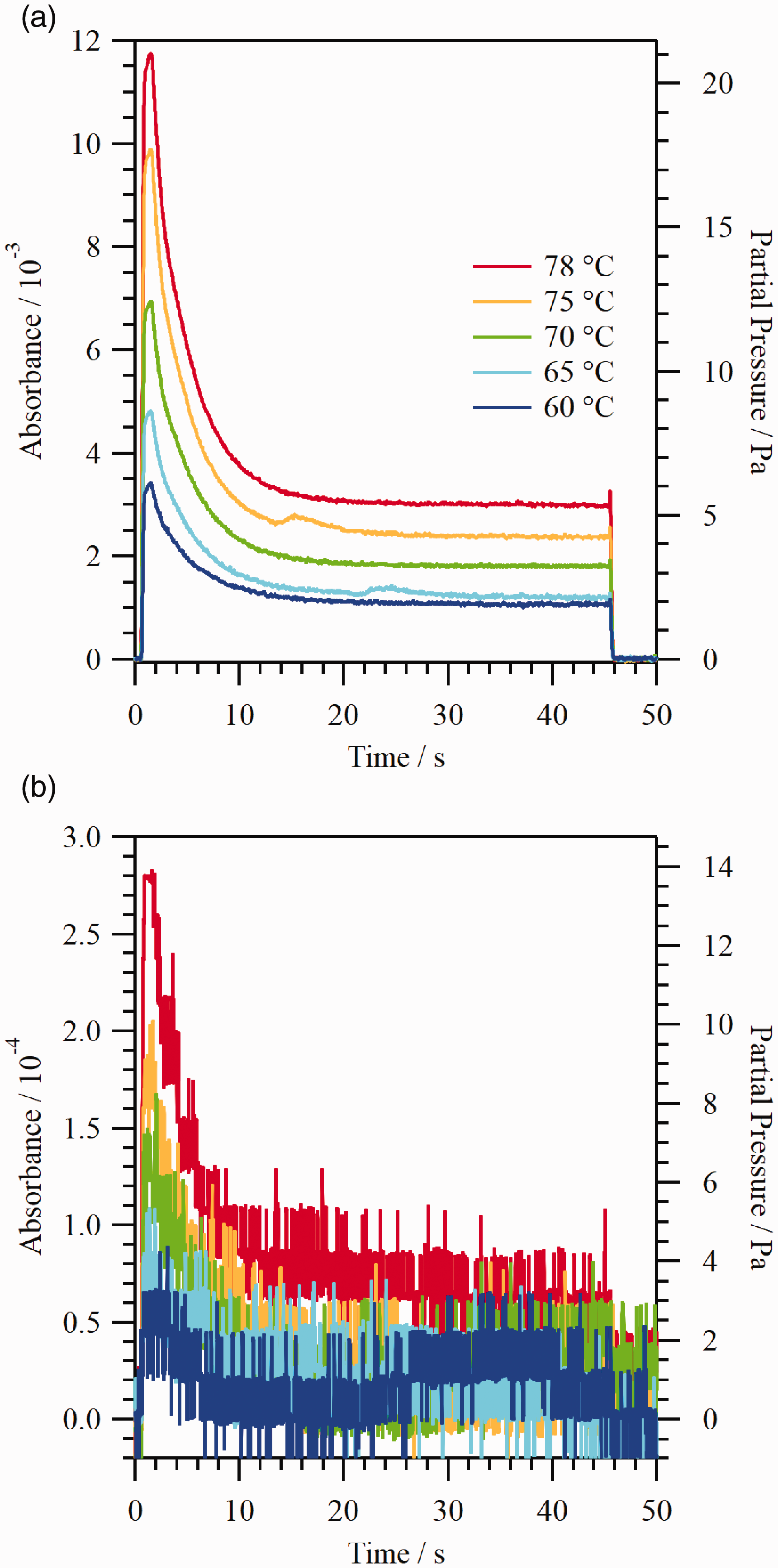
The PDMAT SNR observed in Fig. 5 is high for these flow conditions. However, the SNR will obviously decrease for flow conditions which result in a larger pressure drop between the ampoule and the measurement location than that corresponding to the conditions in Fig. 5 (a larger pressure drop would result in a lower PDMAT partial pressure at the flow cell). For example, the CDG1/CDG2 pressure ratio is in the range of 1 to 2 for CDG2 pressures of ≈2.7 kPa and higher at all flow rates (this range includes the conditions corresponding to Fig. 5). 34 Hence, the decrease in PDMAT partial pressure from the ampoule head space to the measurement location is relatively small. In contrast, the CDG1/CDG2 pressure ratio increases into the range of 8 to 10 for CDG2 pressures in the range of 190 Pa to 610 Pa. While the PDMAT SNR would be degraded for a worst case factor of 10 decrease in PDMAT partial pressure, the signal should still be above the noise without signal averaging for all conditions of interest in this work. In contrast, DMA would be difficult to detect under flowing conditions with a further decrease in partial pressure, at least for conditions comparable to those used this study. Of course, for longer idle times or higher ampoule temperatures, the amount of DMA present in the ampoule head space would be greater.
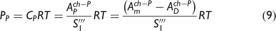
A further validation of the PDMAT and DMA calibration procedure was achieved by comparing an optically determined mass of material removed from the ampoule, after a series of 362 PDMAT injections each lasting 55 s, to a gravimetrically determined mass. For these injections, the ampoule jacket heater setpoint temperature was 75 ℃, flow rates ranged from 0.25 L/min to 1.50 L/min, and CDG2 pressures ranged between 2 kPa and 5.2 kPa. Measurements were performed over the course of two consecutive days. At the end of each day, the ampoule jacket heater was turned off and the valve cluster heater setpoint temperature was decreased to 30 ℃ to reduce DMA generation. The optically determined mass was calculated in the following manner. The time-dependent PDMAT and DMA flow rates, FP and FD, respectively, were calculated from the respective measured partial pressures (see Eqs. 8 and 9)

While this NDIR gas analyzer was specifically tested for PDMAT and DMA, it is suitable for characterizing the vapor delivery of other metal dimethylamido compounds that exhibit an absorption feature corresponding to the filter center wavelength of 10.56 μm (≈947 cm−1), e.g., tetrakis(dimethylamido) titanium (TDMAT) with a feature in the ≈943 cm−1 to ≈950 cm−1 range,15–18,27,33,37–41 tetrakis(dimethylamido) hafnium with a feature in the ≈942 cm−1 to ≈943 cm−1 range,27,42 tetrakis(dimethylamido) vanadium with a feature reported at 944 cm−1, 27 pentakis(dimethylamido) niobium with a feature reported at 938 cm−1, 27 and tetrakis(dimethylamido) zirconium with a feature in the ≈933 cm−1 to ≈936 cm−1 range,27,43 although the NDIR analyzer performance would presumably degrade as the peak absorbance deviated from the filter center wavelength. The DMA 14.03 μm center wavelength filter is also suitable for monitoring the amines corresponding to the hydrogenated ligands of metal ethylmethylamide and metal diethylamide compounds: the N–H bending mode in methylethylamine is observed in the ≈724 cm−1 to ≈725 cm−1 range,31,44 while that of diethylamine is observed in the ≈716 cm−1 to ≈721 cm−1 range.31,32,45 Measurements of the parent metal ethylmethylamide and metal diethylamide compounds would require a replacement for the filter on the PDMAT channel. For example, a ≈10.2 μm center wavelength filter could be used for ethylmethylamides46–49 and a ≈10 μm center wavelength filter could be used for diethylamides.27,40
Conclusion
A NDIR gas analyzer based on direct absorption measurement of PDMAT and DMA was demonstrated for simultaneously measuring the time-dependent partial pressure of these species during vapor deposition processes. Spectral features in the fingerprint region were selected for monitoring the respective species to reduce potential spectral interference between PDMAT and DMA. In addition, a calibration procedure was employed that accounted for the presence of DMA during PDMAT injection. The minimum detectable molecular density (partial pressure) for PDMAT and DMA was ≈2 × 1013 cm−3 (≈0.1 Pa) and ≈5 × 1014 cm−3 (≈2 Pa), respectively, with no signal averaging and for a sampling rate of 200 Hz. At this PDMAT detection limit, it should be possible to monitor PDMAT vapor at the majority of HVM ALD conditions identified in this study. At this DMA detection limit, there are a range of conditions under which DMA cannot be consistently monitored, because of a lower NDIR analyzer sensitivity to DMA compared to PDMAT and because conditions of this study were selected to minimize DMA production. DMA production would be increased at higher ampoule temperatures and longer ampoule idle times between PDMAT injections. This NDIR gas analyzer is also suitable for characterizing delivery processes of other metal alkylamide precursors and the corresponding amine decomposition products, although in the case of some metal alkylamides a different bandpass filter would be required.
Supplemental Material
sj-pdf-1-asp-10.1177_0003702819885182 - Supplemental material for Nondispersive Infrared Gas Analyzer for Partial Pressure Measurements of a Tantalum Alkylamide During Vapor Deposition Processes
Supplemental material, sj-pdf-1-asp-10.1177_0003702819885182 for Nondispersive Infrared Gas Analyzer for Partial Pressure Measurements of a Tantalum Alkylamide During Vapor Deposition Processes by James E. Maslar, William A. Kimes, Brent A. Sperling and Ravindra K. Kanjolia in Applied Spectroscopy
Footnotes
Notes
Acknowledgments
The authors gratefully acknowledge P.F. Ma, J.W. Anthis, and J.R. Bakke for helpful discussions.
Declaration of Conflicting Interests
The author(s) declared no potential conflicts of interest with respect to the research, authorship, and/or publication of this article.
Funding
The author(s) received no financial support for the research, authorship, and/or publication of this article.
Note
References
Supplementary Material
Please find the following supplemental material available below.
For Open Access articles published under a Creative Commons License, all supplemental material carries the same license as the article it is associated with.
For non-Open Access articles published, all supplemental material carries a non-exclusive license, and permission requests for re-use of supplemental material or any part of supplemental material shall be sent directly to the copyright owner as specified in the copyright notice associated with the article.