
Abstract
The aim of this paper is to describe at a system-level, the development of combined regenerative and friction braking technology with emphasis on control strategies and system complexity. The subject of the study has resulted from prior and current involvement of the Control Theory and Applications Centre (CTAC) and MIRA in research and development activities related to control systems for hybrid/electric vehicles. Regenerative braking plays an unquestionable role in the economic success of hybrid/electric vehicles. Current developments in regenerative braking technology are focused on increasing the regenerative braking operating region beyond the limits of vehicle stability which requires sophisticated control strategies that are suitable for safe vehicle operation. For realisation of continual economic viability with further improvement of the technology, advancement should be focused not only on the development of control strategies but also on the minimum increase of vehicle complexity and thereby minimal additional final cost of the vehicle, that is, by utilisation of standard vehicle components (e.g. driveline components and four-channel anti-lock braking system).
I. Introduction
Regenerative braking requires more control strategies than any other systems on the vehicle.1,2 This is mainly due to the extensive legal requirements that have to be satisfied.3,4 Those requirements are especially rigorous for hybrid/electric vehicles (H/EVs) for which the regenerative braking system is activated for a driver deceleration request above 0.1g. For such vehicles, the control system must allow safe operation close to the limits of handling and vehicle stability.
In order to increase the level of recaptured energy during a braking manoeuvre, the regenerative braking torque source should be prioritised in the braking action supplying the regenerative braking torque ahead of the friction brakes. This, however, raises some issues with braking torque control as the regenerative braking torque is usually (except with individual hub motors) delivered via a differential. 5 Due to the high complexity within driveline systems equipped with regenerative braking, not only the legal issues are difficult to accomplish, but so is ensuring correct (safe and comfortable) vehicle operation (e.g. blending of the regenerative braking and friction braking torque).2,5,6
Vehicle deceleration up to 0.1g does not require activation of onboard vehicle safety systems during a braking manoeuvre. 5 This is directly connected with the statement that even for a low friction coefficient surface a driver deceleration request below 0.1g should not cause major vehicle stability issues. However, based on typical urban vehicle operation (for which vehicle deceleration can reach up to 0.5g in 98% of the cases 7 ) and the need for regeneration of energy above the safe 0.1g deceleration level, the range of 0.1–0.5g is considered for regenerative braking activity. This assumption implies that there is interaction of regenerative braking with active driving safety systems (e.g. anti-lock braking system (ABS)), which is a requirement already specified in braking systems regulations.3,4 Deceleration levels greater than 0.5g are referred to as emergency braking cases and are not so frequent (less than 2% 7 ) in standard, daily vehicle operation. On this basis, they are neglected in this study by setting the maximum deceleration level at the value of 0.5g. The paper will expand on additional legal and safety requirements which are taken into consideration for development of appropriate regenerative braking control strategies.
II. Regenerative Braking Legislative Background
There are two legislative documents within the European Union with regard to braking systems in passenger vehicles:
The difference between these regulations concerns only the H/EVs. The detailed requirements for H/EVs are given in the ECE Regulation 13H and 13.11. These regulations divide the braking systems with a regenerative braking mode into two categories, A and B.
Category A – concerns the braking systems where the regenerative braking system is not a part of the main braking system, for example, use of a throttle-off braking.
Category B: non-phased – contains the braking systems where the regenerative braking exists as a part of the main braking system. In systems that fall under this category, the regenerative braking torque can be delivered together with the friction braking torque or slightly later.
Category B: phased – includes systems in which the regenerative braking is a part of the main braking system. There is, however, one difference in comparison: the non-phased systems, namely, the regenerative braking torque can be deployed before the friction braking torque.
There are also other very important legislative records that considerably shape the configuration and control of the braking system in general, for example:
ABS must control regenerative braking. If the ABS wheel speed signal sees excessive slip, it will typically trigger suspension of regenerative braking until next brake or lift-off event.
Furthermore, essential requirements are given for Category B phased system:
‘Intrinsic variations in the torque output of the electrical regenerative braking system (e.g. as a result of changes in the electric state of charge in the traction batteries, or electric motor torque characteristic; see Figure 1 ) are automatically compensated by appropriate variation in the phasing relationship’.
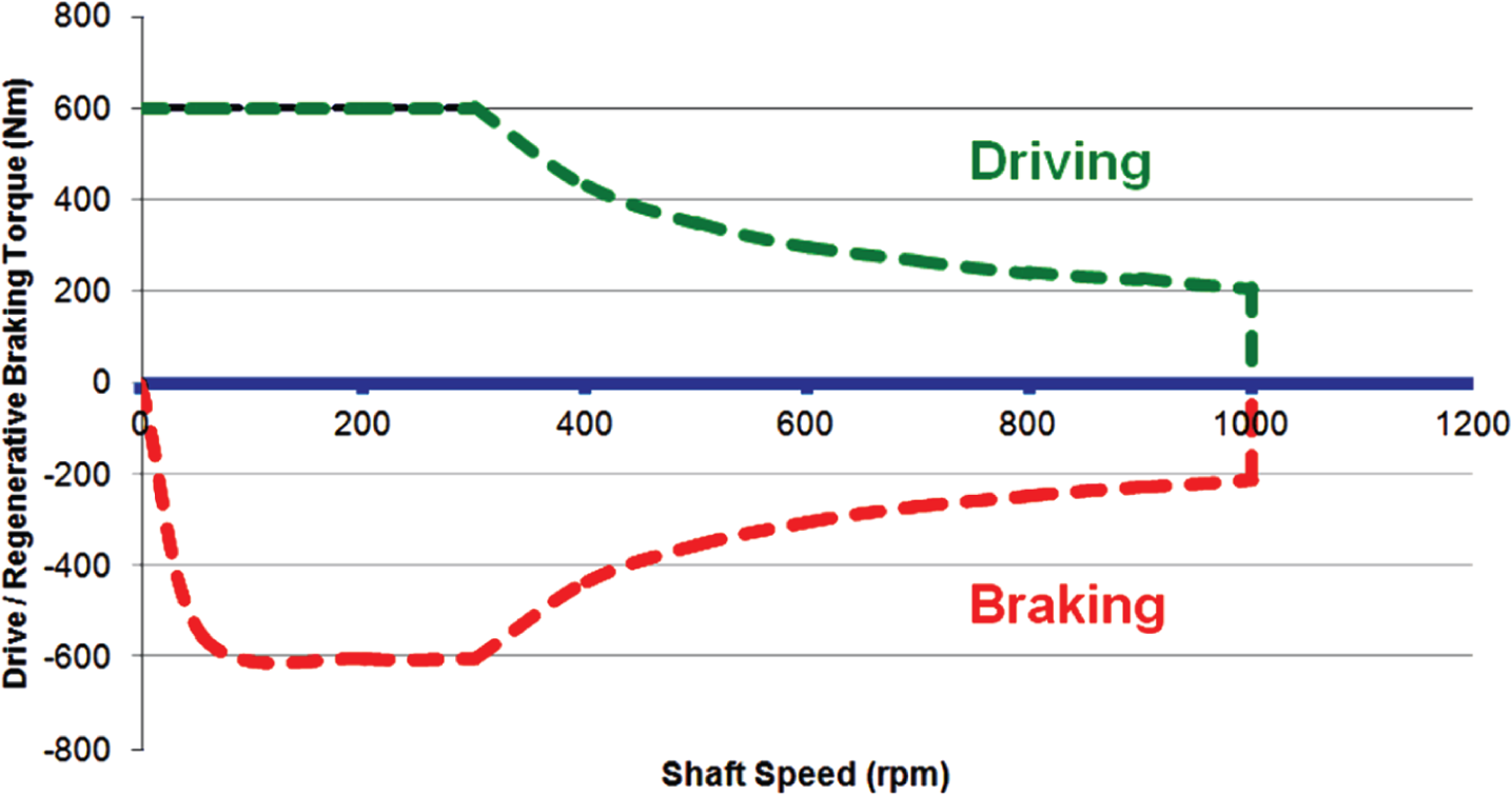
Motor driving/braking characteristics
The above requirement might be fulfilled by appropriate regenerative and friction brake torque control as presented in Figure 2 .
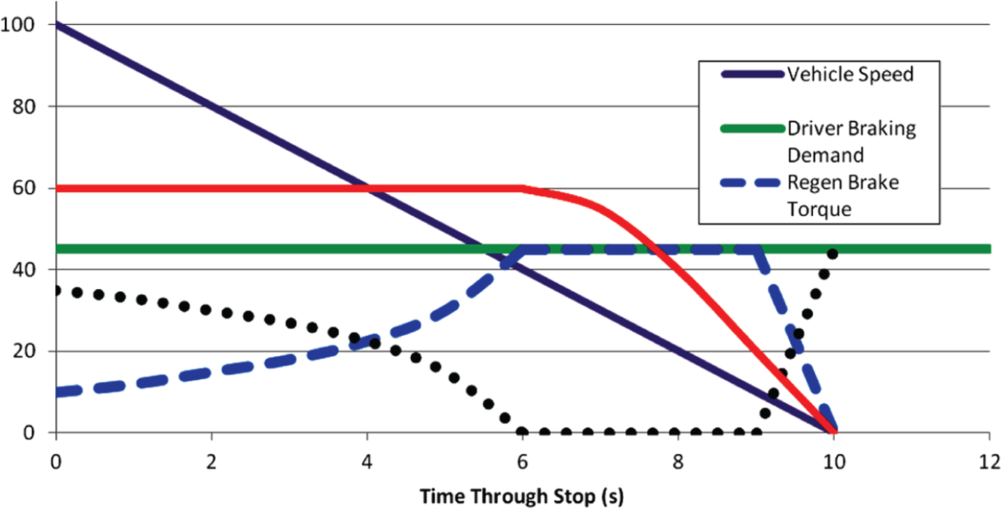
Blending changes in brake torque required through stop
The regenerative braking source plays the principal role in the braking torque delivery. However, when the driver demand oversees the regenerative braking system capability (e.g. due to electric motor torque characteristic; see Figure 1 ), the friction brake is activated.
‘Wherever necessary, to ensure that braking rate remains related to the driver’s braking demand, having regard to the available tyre/road adhesion, braking shall automatically be caused to act on all wheels of the vehicle’.
The above introduces heavy implications for Category B phased systems. In order to explain this issue, let us assume that the vehicle is braking only making use of the regenerative braking source (see Figure 3 ).
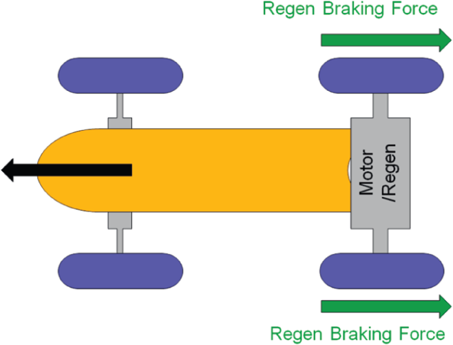
Initial braking torque split for systems that fall into Category B phased
Suddenly, one of the wheels is losing traction by driving on a patch of ice (see Figure 4 ). According to the law requirements, the regenerative braking controller should automatically apply braking torque on the non-regenerative braking axle/wheels (see Figure 5 ).
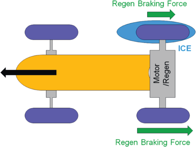
First stage of braking torque correction when the low mu surface affects one of the regenerative braking wheels
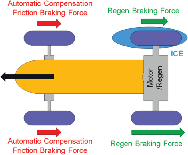
Second stage of braking torque correction (compensation) required by braking law regulations
Such braking control requirement does not exist with regard to conventional braking systems (non-regenerative braking systems).
III. Implications of Braking System Regulations
The regenerative braking regulations describe in a detailed manner the braking system properties. In order to introduce the complex braking system algorithms, the supervisory regenerative braking controller is frequently used. The supervisory regenerative braking controller is required as regenerative braking cannot replace friction brakes of the vehicle due to the following:
Braking system law requirements
Limitations of energy storage devices
Charging rate
Capacity
Battery aging
Limited available power of electric motor(s)
Performance degradation
Thermal characteristics of all components (e.g. battery and electric motor)
Following the above, the base regenerative braking controller functionalities might be specified as follows:
Driver braking torque arbitration
Braking torque distribution between:
Front and rear axle (see Section III A)
Regenerative braking and friction brake (blending)
Low-velocity regenerative braking switch-off
Appropriate action in case of ABS event (see Section III B)
Pedal feel (see Section IV)
In this text, some of the regenerative braking control functionalities will be briefly presented based on the experience of the authors.
A. Modified Brake-Force Distribution for Rear Axle Regenerative Braking Vehicle
A very interesting regenerative braking control idea might be introduced for Category B phased systems. In order to maximise on the recaptured energy, the regenerative braking axle should be prioritised in the braking activity. 6 Such a situation can be presented making use of the front–rear axles braking force/vehicle weight characteristic (see Figure 6 ).
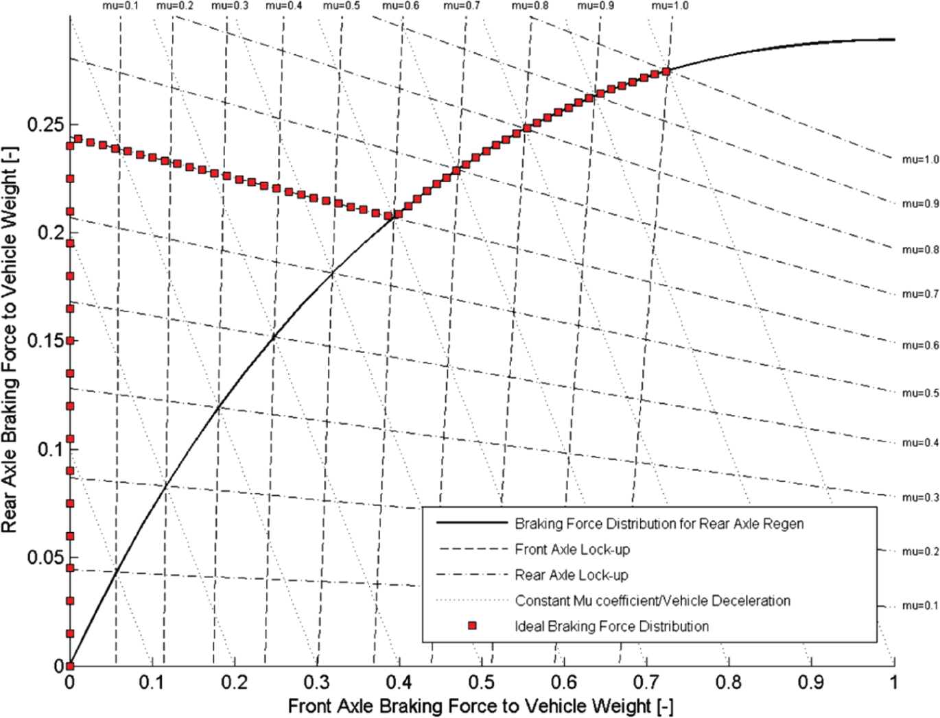
Brake-force distribution for rear axle regenerative braking vehicle. Result for 0.6 surface adhesion level
There are, however, some issues with the introduction of this braking strategy. The main one concerns the mu coefficient estimation for correct (vehicle-instability-free) operation. Given the current state of the art in the mu coefficient recognition, that is, impossibility for continuous, real-time mu estimation, the mu coefficient can be set on the lowest, safe level of 0.1. Such an approach gives also a substantial energy gain.
B. Regenerative Braking Strategies during ABS Event
The law regulations also specify the braking system actions when the ABS event occurs. In order to ensure safe vehicle operation, it is necessary to use an appropriate regenerative braking strategy. Some of them are presented in Figures 7 and 8 .
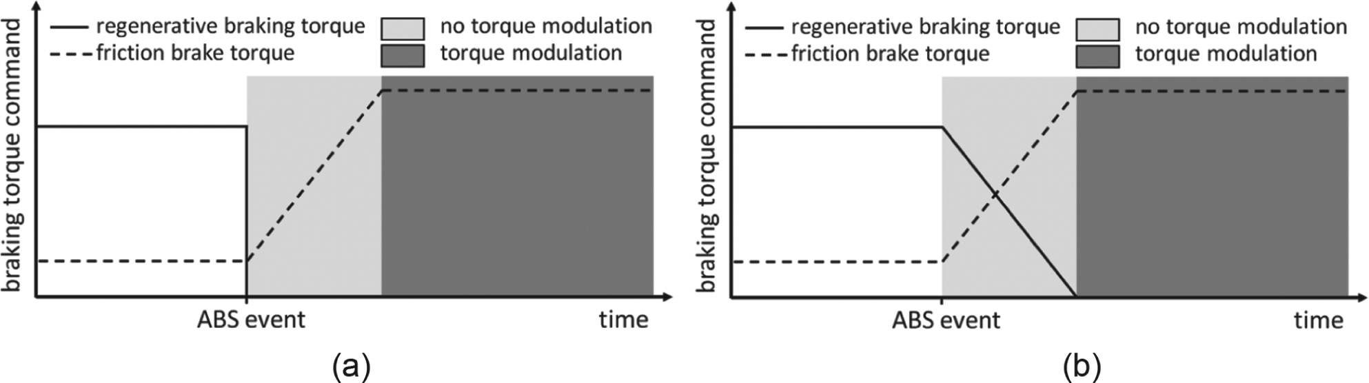
Termination of regenerative braking during ABS event: (a) without any blending phase; (b) regenerative braking torque ramp down to zero
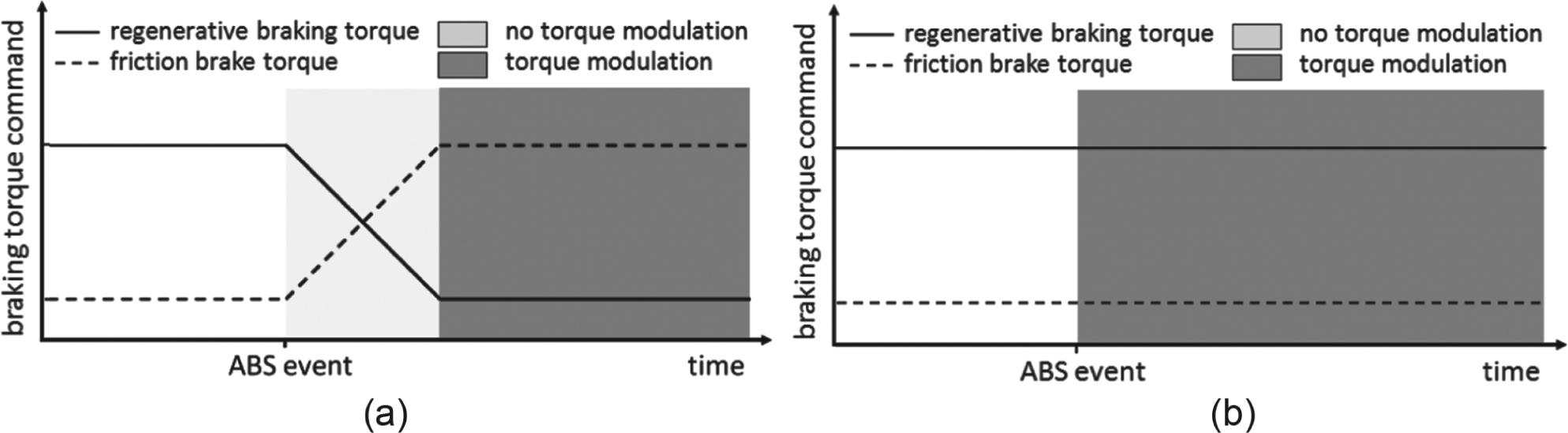
Termination of regenerative braking during ABS event: (a) regenerative braking torque ramp down to a variable residual level; (b) regenerative braking torque modulation for ABS purposes
For the first two strategies, the regenerative braking torque is reduced to zero (instantly or gradually) when the ABS event occurs. This, however, does not ensure that a great amount of vehicle kinetic energy is recaptured.
Much higher energy recapture is observed for control systems that use the non-zero regenerative braking torque delivery during an ABS event (see Figure 8 ). These regenerative braking control strategies, however, present some shortcomings that are currently creating a perfect field for researchers and engineering activity! The first issue concerns the mutual cooperation of the regenerative braking and ABSs. For systems that use the non-zero regenerative braking torque when an ABS event occurs, vehicle instability is observed.
There are also some technical issues with regenerative braking systems, for example, ability to replicate the hydraulic braking system torque modulation (see Figure 8(b) ) for simulation of the well-known ABS functionality. Some results presented in Oleksowicz et al. 5 indicate issues with the drive train setup, for example, one electric motor fitted with an open differential that causes vehicle instability when regenerative braking and ABS operate mutually.
IV. Regenerative Braking Hardware – Pedal ‘feel’ Compensation
There are also other issues connected with the regenerative braking that need to be addressed. One of these is the pedal feel compensation. For the systems that use the regenerative braking mode, the braking demand is usually accessed on the basis of the brake pedal position via information from a pedal position sensor. In addition, the system must consider the following:
Pedal feel compensation
Brake line pressures must be separated from master cylinder
A separate energy source to apply brakes
Need for some form of brake by wire control
Nissan Motor in collaboration with Hitachi Automotive Systems developed a new braking system currently in use in two Nissan vehicles, namely, Nissan Leaf and Nissan Infiniti Hybrid. 8
The novel component of the braking system is the electrically driven intelligent brake unit (EDIBU). It has two main functions in the system. It provides hydraulic boost (similar to a vacuum booster in a conventional vehicle) to amplify the brake force applied by the driver on the brake pedal. Additionally, it operates as a brake pedal stroke simulator, that is, it generates a proper reaction force at the brake pedal during regenerative braking, so that the driver does not perceive any changes. The EDIBU is presented in Figure 9 .

The electrically driven intelligent brake unit (EDIBU)
The master cylinder of the unit consists of two chambers similar to the conventional master cylinder. However, the pressure in the primary chamber can be generated twofold, by means of the pushrod attached to the brake pedal (similar to the conventional braking unit) and by means of the electric motor coupled with the rotational–translational converter (the ball screw) and the primary piston. The primary piston and the pushrod are connected by means of two compensating springs (see Figure 9 ). When the regenerative braking occurs, the ball screw retracts the primary piston to reduce the hydraulic pressure in the master cylinder. The principle of operation of the EDIBU during regenerative braking is presented in Figure 10 .
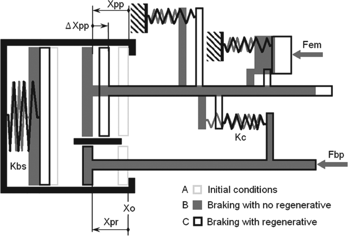
The principle of operation of the EDIBU during braking with and without regenerative braking
When no braking force is present at the brake pedal, the primary piston and the pushrod remain at the initial position X0 (case A in Figure 10 ). When the braking force is applied, but no regeneration braking occurs, the primary piston follows the pushrod in a servo manner. The distance covered by the pushrod and the primary piston is identical, namely, Xpr = Xpp (case B in Figure 10 ). The movement of both components generates hydraulic pressure which contracts the spring with stiffness Kbs representing the stiffness of the braking system. When the regenerative braking is applied, the primary piston retracts by the distance ΔXpp with respect to the current position of the pushrod (case C in Figure 10 ) reducing the pressure in the master cylinder. The pressure reduction leads to decline of the frictional braking torque; however, this amount is replaced by the regenerative braking provided by the driving electric motor/generator of the vehicle. Additionally, the drop in pressure reduces the reaction force generated by the hydraulic fluid, which is fed back to the brake pedal. However, this force is compensated by means of the force accumulated in the compensation spring when the primary piston retracts with respect of the pushrod. In such a scenario, the energy is recovered without compromising natural braking performance perceived by the driver.
V. Conclusion
H/EVs are far more complex systems than vehicles with conventional propulsion systems. This is determined not only by the systems control requirements but for the most part by the legislative regulations and need for a centralised control algorithm. The legal requirements related to H/EVs are considerably more precise and demanding in comparison to the well-understood conventional vehicles (non-H/EVs). Researchers and engineers must consider the following:
Need to get system specification right
Understand all legal implications for intended market
Understand targets and customer expectations – must select concept with appropriate system complexity for each application
Must ensure appropriate pedal feel
Braking inconsistencies, which reduce confidence and driver satisfaction
Systems integration and detailed development required to achieve appropriate blending and consistent feel
For high-deceleration regenerative braking must ensure interaction of regenerative braking controller with ABS
This, however, creates an excellent area of research for control engineers demanding multidisciplinary knowledge.
Footnotes
Funding
This research received no specific grant from any funding agency in the public, commercial or not-for-profit sectors.