
Abstract
In this article, the design of a low-cost educational liquid-level sensor circuit is described. The sensor is of capacitive type and is in the form of a parallel plate capacitor made up of two aluminium foil papers stuck on opposite sides of the container whose liquid level is to be measured. The sensor works on the principle that its capacitance changes with the level of liquid in the container as a result of the change in permittivity between the plates. Thus, by calculating the capacitor value, one can calculate the level of the liquid in the vessel. In this article, the capacitor value is calculated using a microcontroller-based circuit where an RC circuit is formed and the rise-time of the voltage across the capacitor is measured and is then related to the level of the liquid. The results are found to have good linearity and repeatability, and it is shown that the liquid level can be measured accurately and with low cost using some readily available basic components.
Keywords
Introduction
The level of liquid in a storage vessel is one of the important parameters in any process industry. 1 It is generally required to measure and then control the level of the liquid. Many liquid properties may affect the decision of developing and using a liquid-level sensor. 2 Electrical conductivity, buoyancy, acidity, electrical permittivity, electrical conductivity, etc., are some of the factors that can be considered before developing and using a sensor in a liquid.
Many different types of liquid-level sensors are used throughout industries. Some sensors are a contact type that are immersed inside the liquid, while some others are contactless where the sensor assembly has no contact with the liquid. Contact level sensors are like pressure sensors 3 mounted at the bottom of the container, resistive wire 3 and capacitive sensors4,5 placed vertically inside the container, float sensors at the top of the liquid, optical fibre sensors 6 and so on. Contactless level sensors are like capacitive sensors placed on the outside members of the container, 7 ultrasound or microwave sensors 8 placed at the top of the liquid, not touching the liquid, image sensors 9 and so on. The contactless sensors, in general, have the advantages that they have longer life spans, and they can be used to measure the level of any kind of liquid, but they are comparatively more costly and may require various environmental precautions during the measurements. Contact sensors have the advantage of low cost, but they cannot be used with corrosive liquids, such as acids or most other chemicals.10,11
The sensor presented in this article is a microcontroller-based low-cost capacitive sensor used to measure the level of liquid (water) in a storage vessel. The use of capacitive techniques to measure the liquid level is not new and many researchers have developed various techniques for this purpose.
Toth et al. 12 describe the design of a precision capacitive sensor using a capacitance-controlled oscillator and a microcontroller. The authors report that the liquid level could be measured to an accuracy of 1 mm over a 4-m range, with a resolution of 0.1 mm using their technique.
Mohr et al. 13 present a new method for a self-calibrating capacitive liquid-level sensor. Their arrangement consisted of three parallel electrodes on top of each other, where the capacitance between the electrodes depends on the liquid level. With specially developed electronic circuits, the authors measured the capacitances, converted into digital values and transferred to a computer for processing.
A contactless capacitive liquid-level sensor is described by Molex. 14 The sensor mounts outside a container using pressure-sensitive adhesive, and can measure the level of the liquid inside the container. The design is based on a flexible printed circuit that can be attached to flat or curved surfaces externally. Outputs are available from the sensor for various communication interfaces such as USB, I2C and so on.
Bera et al. 15 describe the development of a contactless capacitive liquid-level sensor for conductive liquid. The sensor is in the form of a uniform circular cylinder and is made up of materials like glass, ceramic or plastic. The conducting liquid column is taken as one electrode, and a noninductively wound, short-circuited, outside coil is taken as the other electrode of a variable capacitor. A bridge circuit and an operational amplifier are used to measure the change in capacitance, and the bridge output is calibrated to indicate the liquid level.
A new capacitive method is presented by Canbolat 16 to detect the liquid level. The proposed method is based on the measurements of capacitances of three parallel plate capacitive structures, designated as level, reference and air sensors. A capacitance-to-digital converter integrated circuit is used to measure the capacitance to an accuracy of ±4 pF, hence giving highly accurate height measurements. It is claimed by the author that the developed system compensates for different physical parameters, such as temperature, liquid type, air gap, dust and so on.
Guirong and Shuyue 17 present a capacitive liquid-level sensor with four electrodes. The electrodes are mounted on the inside wall of a cylindrical vessel. The authors report a linear relationship between the measured capacitance and the liquid level even when the vessel is tilted.
Roy and Santhosh 18 propose a capacitive liquid-level sensor with increased linearity, which is also independent of the permittivity of the liquid used. In their method, the capacitance is first converted to frequency by a timer circuit and then the frequency is converted to voltage by a frequency-to-voltage converter. An artificial neural network is used to linearize the non-linear relationship and the dependency on permittivity of the liquid.
Commercially available liquid-level sensors are considerably expensive. The liquid-level sensor developed in this article has the advantage of very low cost, as the sensor elements are designed using a pair of aluminium foil papers stuck externally at opposite sides of the container. This type of sensor can be used in educational control or electronics laboratories to teach theory and practice of liquid level measurement and control. The sensor electronics is based on a microcontroller, and this microcontroller can be used as the digital controller in the project where the liquid level measurement or control is to be made.
Principle and construction of the sensor
Figure 1 shows the block diagram of the sensor device. The sensor element consists of two aluminium foil papers stuck externally at opposite faces of the container, thus forming a parallel plate capacitor. The container is 26 cm in length, rectangular in shape with dimensions of 8.5 cm × 11 cm. The physical shape of the plates is not important, but in this example a rectangular shape is used. An RC circuit is formed and the capacitor voltage is fed to a microcontroller. The microcontroller calculates the value of the capacitor by measuring the rise-time of the RC circuit. Since the capacitance changes with the level of the liquid, the liquid level is calculated and displayed on an LCD using the formula derived in the next section. Note that here the LCD is used to display the results, whereas in a normal liquid-level monitoring or control application it may not be necessary to use an LCD.
Block diagram of the developed sensor.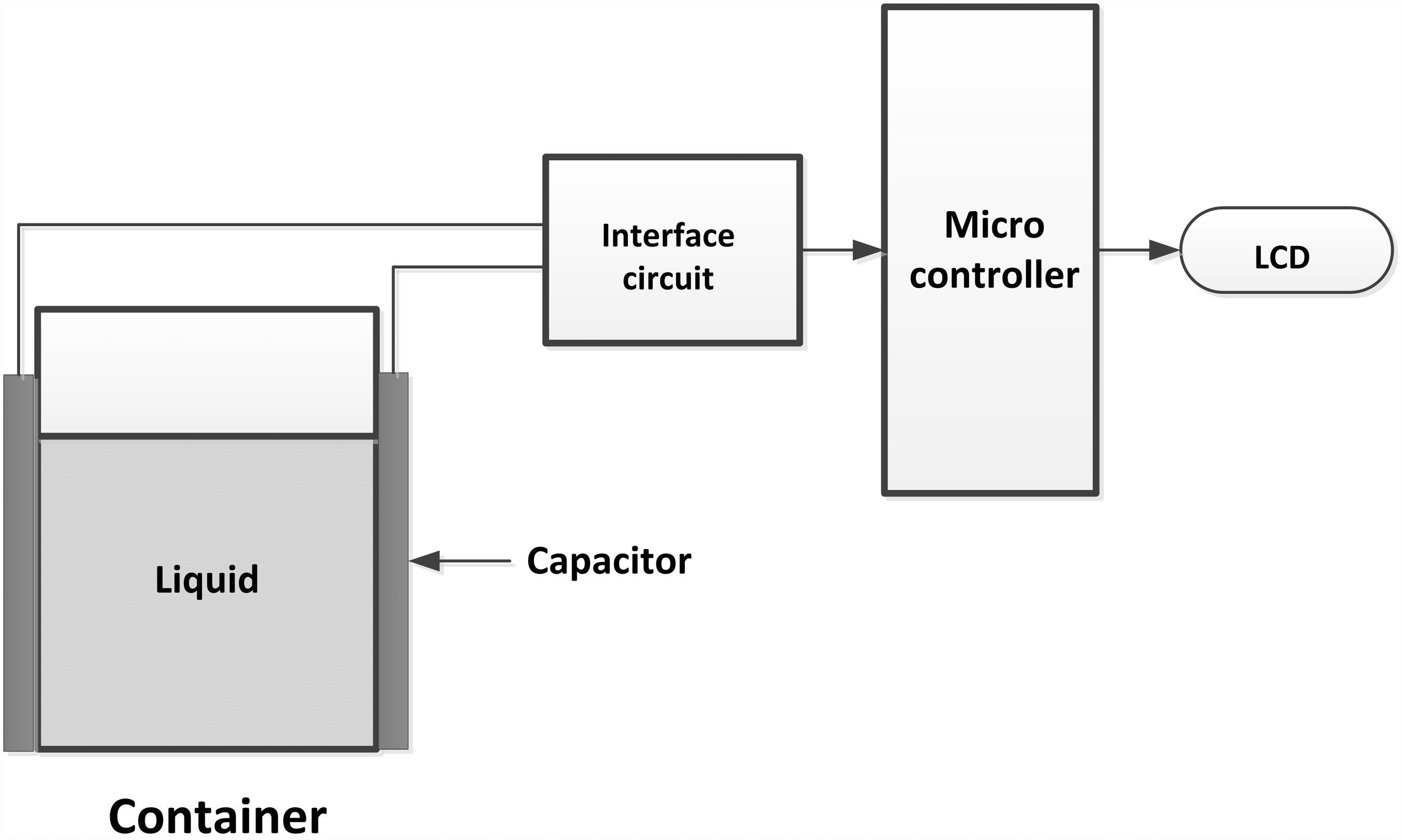
The capacitance and liquid level
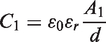
The capacitor basically consists of two parallel plate capacitors C1 and C2 connected in parallel, where C1 is the capacitance inside the liquid and C2 is the capacitance outside the liquid (the series capacitor due to the container membrane should also be taken into account for a more correct analysis). We can write the following two equations for the capacitors

In theory, one can use equations (1) and (2) to derive an approximate theoretical equation for the capacitance. But, it would be easier and also more accurate to derive the capacitance–height relationship using an experimental approach.
Deriving the capacitance–height relationship
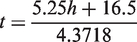
The value of the capacitor is measured by forming an interface RC circuit and then measuring the rise-time of the voltage across the capacitor. The circuit diagrams of the capacitor and the interface circuit are shown in Figure 2. A voltage divider circuit is formed using two 3.9 K resistors and the mid-point voltage is fed to the positive input of an analogue comparator inside the microcontroller. A 330 K resistor is connected in series with capacitor Cx. Initially, the capacitor is discharged through the 290 ohm resistor. At the beginning of the measurement a voltage is applied via the output port RC0. The voltage across the capacitor rises exponentially, and when it reaches half of the applied voltage, the output of the analogue comparator changes polarity and this is detected by a program running on the microcontroller. The value of the capacitor is then calculated as described next, and finally the level of the liquid is found. The reason for using an analogue comparator is because the capacitor value could be measured quickly and accurately, as the capacitor values are very low (in pF range) and the capacitor voltage could not be measured by polling an input port. The advantage of using the interface circuit in Figure 2 is that the capacitor rise-time is independent of the supply voltage Vi and it is not necessary to know what the actual value of the supply voltage is at any time.
Circuit diagram of the sensor and interface circuit.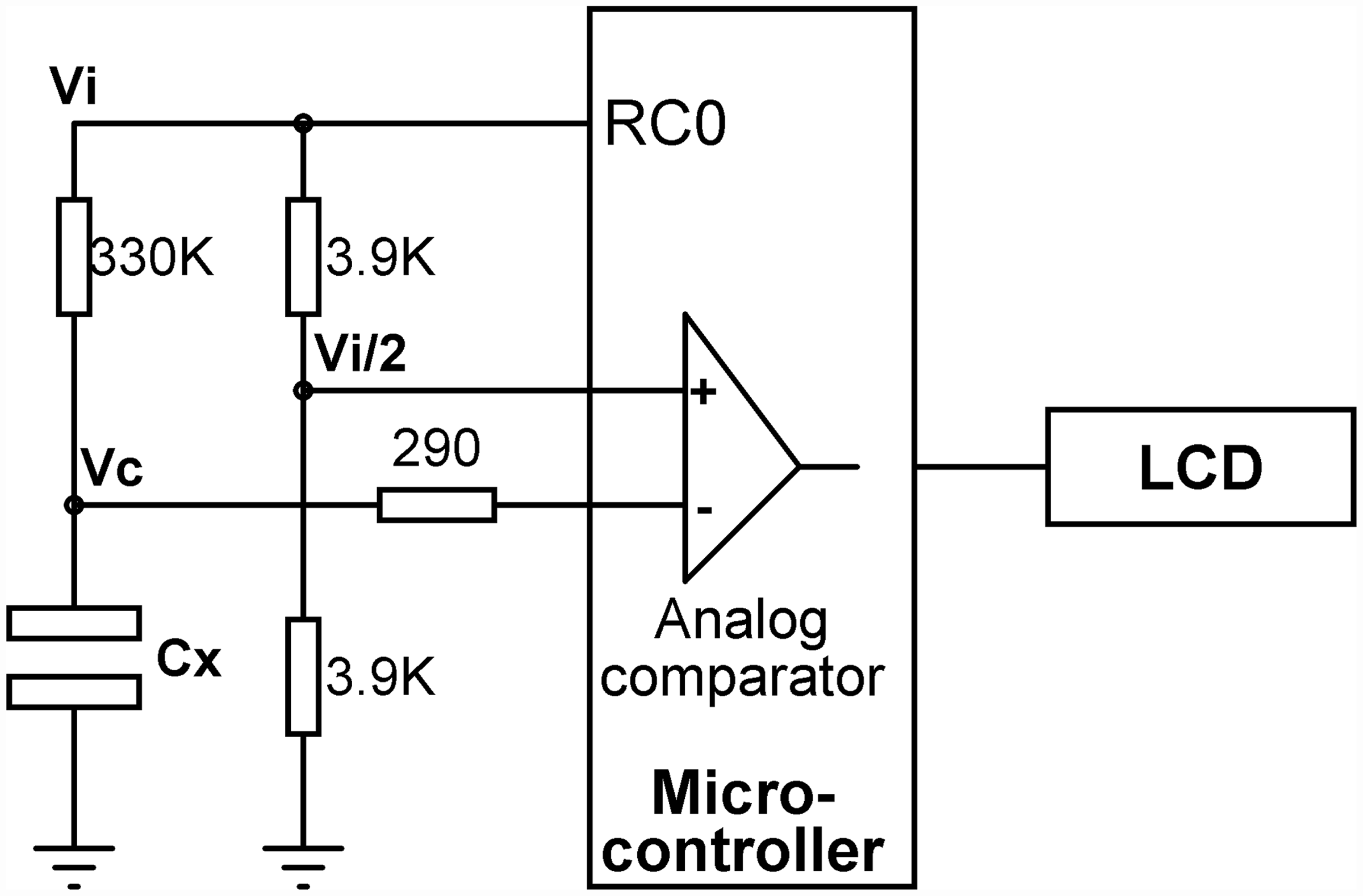
The voltage across the capacitor rises exponentially, given by
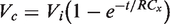

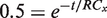
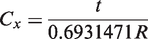
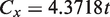
Figure 3 shows a graph of the measured capacitance against the level of the liquid. From this figure, the linear equation describing the relationship between the capacitance and the height can be derived as
Measured capacitance and the liquid level.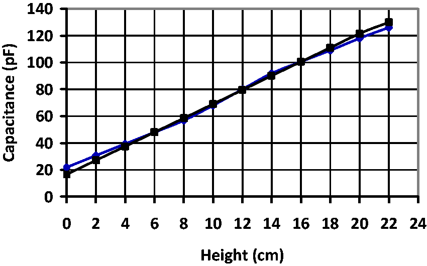

Note that equation (8) is also plotted on the graph in Figure 3 and clearly the equation describes the experimental behaviour of the sensor accurately.
By combining equations (7) and (8), we can calculate the level of the liquid using
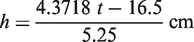
Note that for the complete length of the capacitor plates (26 cm), the capacitor rise-time changes from about 3 µs to 32 µs. From equation (10) we can see that the rate of change of rise-time with the height is about 1 µs/ cm. The resolution of the height measurement is 1 cm since we cannot measure the time more accurately than 1 µs. This result should be adequate in educational applications. The measurement accuracy could be improved significantly by using a higher clock frequency or a higher value for the charging resistor.
Development of the sensor
The hardware
Figure 4 shows the overall circuit diagram of the sensor. Here, a PIC18F45K22-type microcontroller is used, although any other type or model microcontroller could also have been used. The main requirement is that the microcontroller should support at least one timer module and one analogue comparator module. The microcontroller is operated from an 8 MHz crystal. A 21 × 16 character LCD is connected to port B of the microcontroller. Port pin RC0 of the microcontroller provides the supply voltage to the interface circuit during measurement.
Overall circuit diagram of the sensor.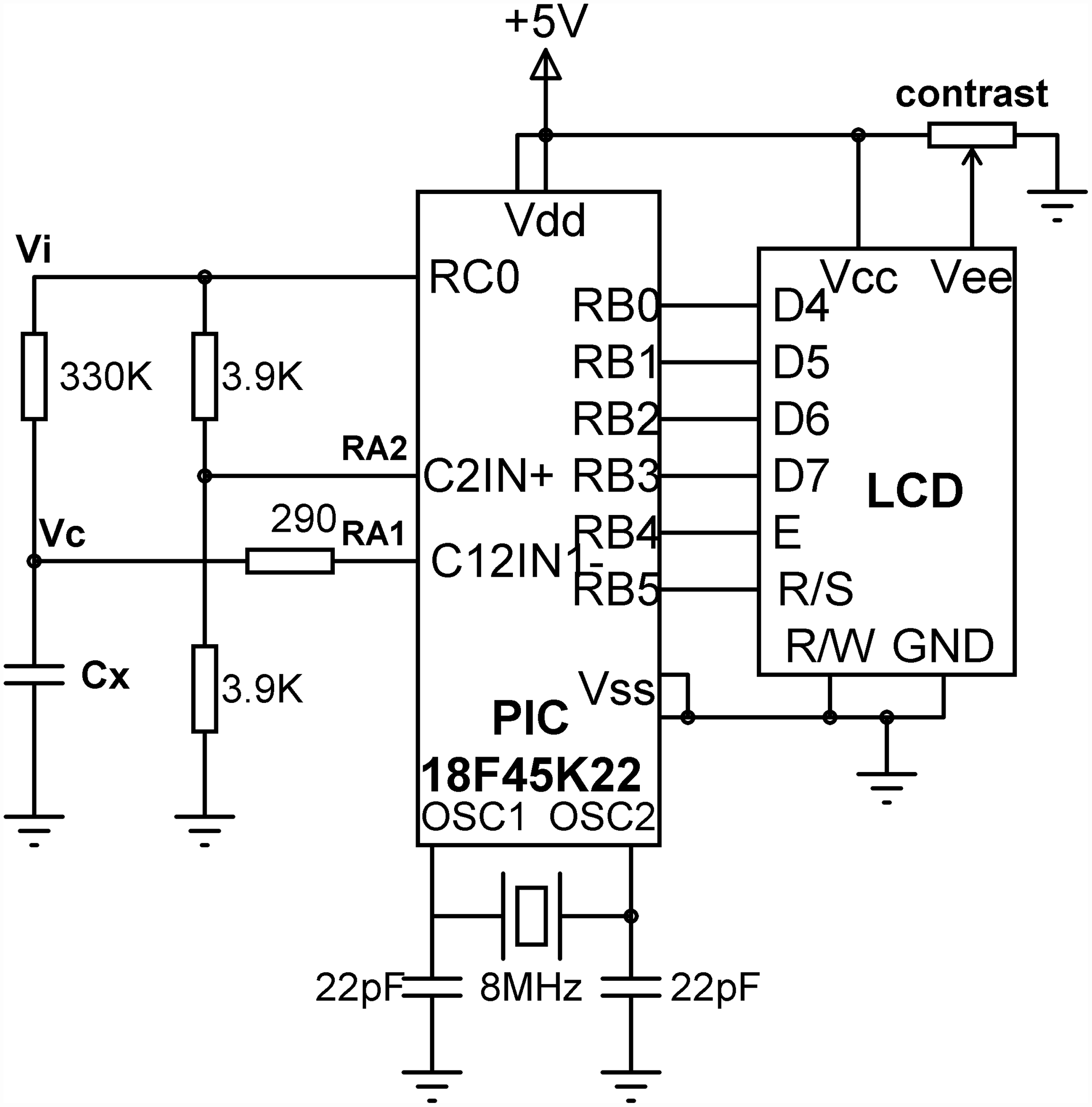
The EasyPIC V7 development board is used during the development and testing. The interface circuitry was built on a small breadboard. EasyPIC V7 is a complete microcontroller development board manufactured by mikroElektronika,
19
supporting programming and in-circuit debugging, and consisting of many hardware components. The basic features of this board are (see Figure 5):
36 LEDs 36 push-button switches USB and USB-RS232 interface four-digit, seven-segment LED 16 × 2 LCD and 128 × 360 graphics LCD DS1820 and LM35DZ temperature sensors RS232 interface piezo buzzer mikroICD in-circuit debugger different size microcontroller sockets and I/O connectors power supply
The EasyPIC V7 microcontroller development board.

The basic features of the PIC18F45K22 microcontroller are as follows:
32 kB flash program memory 1536 bytes of data RAM 256 bytes EEPROM 36 I/O ports 30 10-bit ADC channels 2 × SPI and 2 × I2C bus lines 2 USART 3 × 8-bit and 4 × 16-bit timers 2 × analogue comparators
The PIC18F45K22 microcontroller contains two analogue comparators. In this application, Comparator 2 is used where RA1 (C12IN1−) and RA2 (C2IN+) are the Comparator 2 inverting and non-inverting inputs, respectively.
The software
The software was developed using the mikroC Pro for PIC compiler. 20 This is a powerful C compiler developed for the PIC16 and PIC18 family of microcontrollers. The mikroC Pro for PIC language supports many libraries for peripheral devices, including USB, RS232, CAN bus, I2C, SPI, LCD, SD card, sound library and many more. An integrated development environment (IDE) is provided where the program can be written and compiled on a PC. The compiled program can be simulated on the PC, or it can be downloaded to the target microcontroller and in-circuit debugging tools can be used to test the overall system in real time.
The operation of the program is simple and is shown in Figure 6 in the form of a Program Description Language (PDL). At the beginning of the program, various registers are declared, the LCD and analogue comparator module are initialized, and Timer 0 is configured for 16-bit operation with a basic count time of 1 µs; thus, an accurate and easy measurement is possible. The main program executes in an endless loop where the capacitor is initially discharged by calling to function ‘discharge’, timer registers are cleared to zero, and the timer is started and voltage is sent via port pin RC0 to start the measurement. The voltage across the capacitor rises exponentially and the measurement stops when the analogue comparator output changes polarity, i.e. when the capacitor voltage reaches half the supply voltage. At this point the timer is stopped and the timer count is converted into real elapsed time. The level of the liquid is then calculated using equation (9). This process is repeated continuously with 1 s delay between each measurement.
PDL of the program.
The initialization of Timer 0 for a count of 1 µs is as follows:
21
the clock frequency is 8 MHz, and thus the clock period is 0.125 µs. The PIC18F45K22 microcontroller timer count rate is given by


As the 16-bit timer counts from 0 to 65,535, the maximum rise-time that can be measured will be just over 65 ms, which is well within the required range of 32 µs (see equation (9)).
The program in Figure 7 displays the capacitance and the liquid level in rows 1 and 2 of the LCD, respectively. The program listing of the developed sensor system is given in Figure 7.
Program listing of the developed sensor system.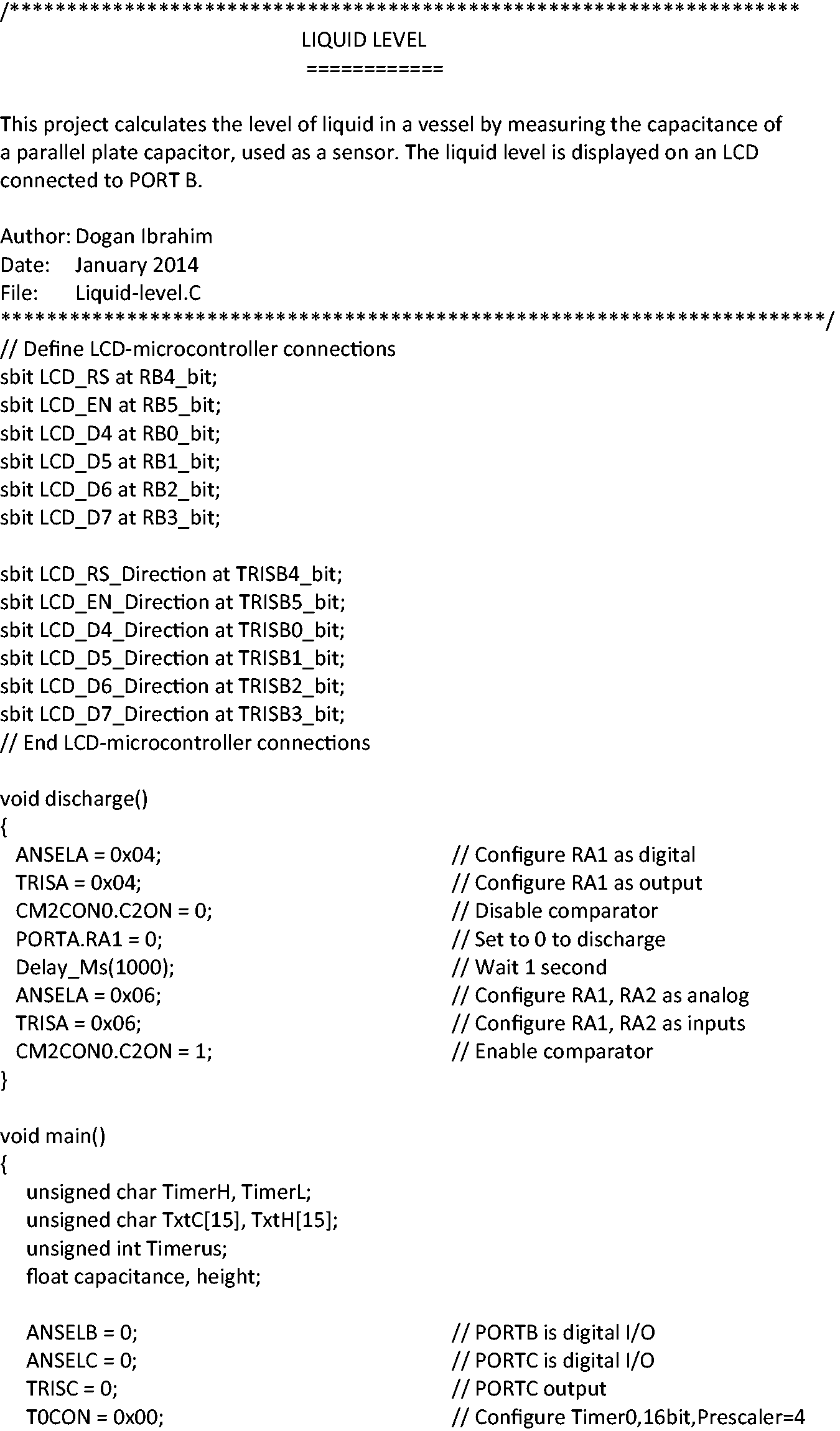
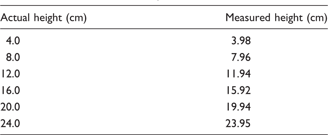
Results and discussion
Measured and actual liquid level.
Conclusions
Liquid-level sensors are used in liquid level monitoring and control applications. The cost of commercially available liquid-level sensors is considerably expensive. In this article, the design of a low-cost educational capacitive liquid-level sensor circuit has been described. The sensor element simply consists of two aluminium foil papers stuck on either side of the external membrane of the container. It is shown in the article that a linear relationship exists between the height of the water in the container and the rise-time of the voltage across the capacitor. A PIC microcontroller is used to measure the rise-time and then to display the water level on a LCD. In real water-level monitoring and control applications, the same microcontroller could also be used as the digital controller of the overall system.
The tests were carried out using a microcontroller development system. The interface circuitry and the PIC microcontroller chip can easily be mounted and soldered on a small PCB and used in educational water-level monitoring and control applications. The sensor system described in this article has been used successfully at the Near East University in third year control engineering laboratory experiments by undergraduate students of the electrical and electronic engineering course. Here, students develop a control algorithm for a water-level controller system consisting of a container, a small water pump and the sensor system described in this article. The microcontroller used in the sensor design is used as the digital controller, thus eliminating the need for an additional controller. A survey was conducted among 15 students completing the laboratory experiment where students were asked to comment on the system. Twelve students (80%) had good results and found the experiment very informative. Two students (13%) had difficulty in getting consistent results due to the lack of practical project experience and one student (7%) had no attendance and did not perform the experiment.
Footnotes
Conflict of interest
None declared.
Funding
This research received no specific grant from any funding agency in the public, commercial, or not-for-profit sectors.