
Abstract
This paper presents the experimental results obtained from a memristor-based Wien-bridge oscillator implemented using a new memristor emulator. The memristor emulator can be implemented using off-the-shelf components. The experimental results show that nonlinear chaotic as well as linear oscillations can be obtained from the same circuit by careful adjustment of the value of a single resistor. The proposed circuit can be easily presented in an undergraduate laboratory course to demonstrate the use of memristors in generating chaotic oscillators.
Keywords
Introduction
At present there is a growing interest in developing chaotic circuits. This is attributed to the wide range of applications of these circuits in communication, medical applications and neural networks. This is explained in a large number of publications in this area using different active elements and nonlinear circuits; see for example literature1–20 and the references cited therein. Of particular interest here are the Wien-bridge oscillator-based chaotic circuits.4–20 This is attributed to the simplicity and popularity of the Wien bridge oscillator.
On the other hand the memristor and its use as a nonlinear element in realizing chaotic oscillator circuits are gaining an increasing interest.18–20 However, the verification of the functionality of the Wien-bridge memristor-based chaotic oscillators is usually performed using SPICE models and/or MATLAB calculations. This is attributed to the commercial unavailability of the memristor. SPICE simulations may be attractive but experimental verification is more attractive as it gives real hands-on experience on the use of memristors and their applications. Despite the fact that there are many memristor emulators based on commercially available active elements and discrete components, to the best of our knowledge none of these emulators has been used for verifying the functionality of the memristor-based Wien bridge chaotic oscillators.
The major intention of this paper is to present the experimental results obtained from such a circuit. Moreover, since the memristor behaves as a linear resistor at high frequencies, the feasibility of obtaining sinusoidal oscillation from a memristor-based chaotic Wien-bridge oscillator will be investigated. The proposed circuit is very simple and uses off-the-shelf components and can be easily implemented in an undergraduate laboratory to demonstrate the use of memristors and the generation of chaotic oscillations.
Analysis
Although there are four types of the well-known Wien-bridge oscillator circuits, the circuit shown in Figure 1 is the most commonly used one. Assuming ideal operational amplifier, routine analysis yields the characteristic equation of the circuit of Figure 1 given by
Chaotic oscillator circuit using memristor circuit emulator.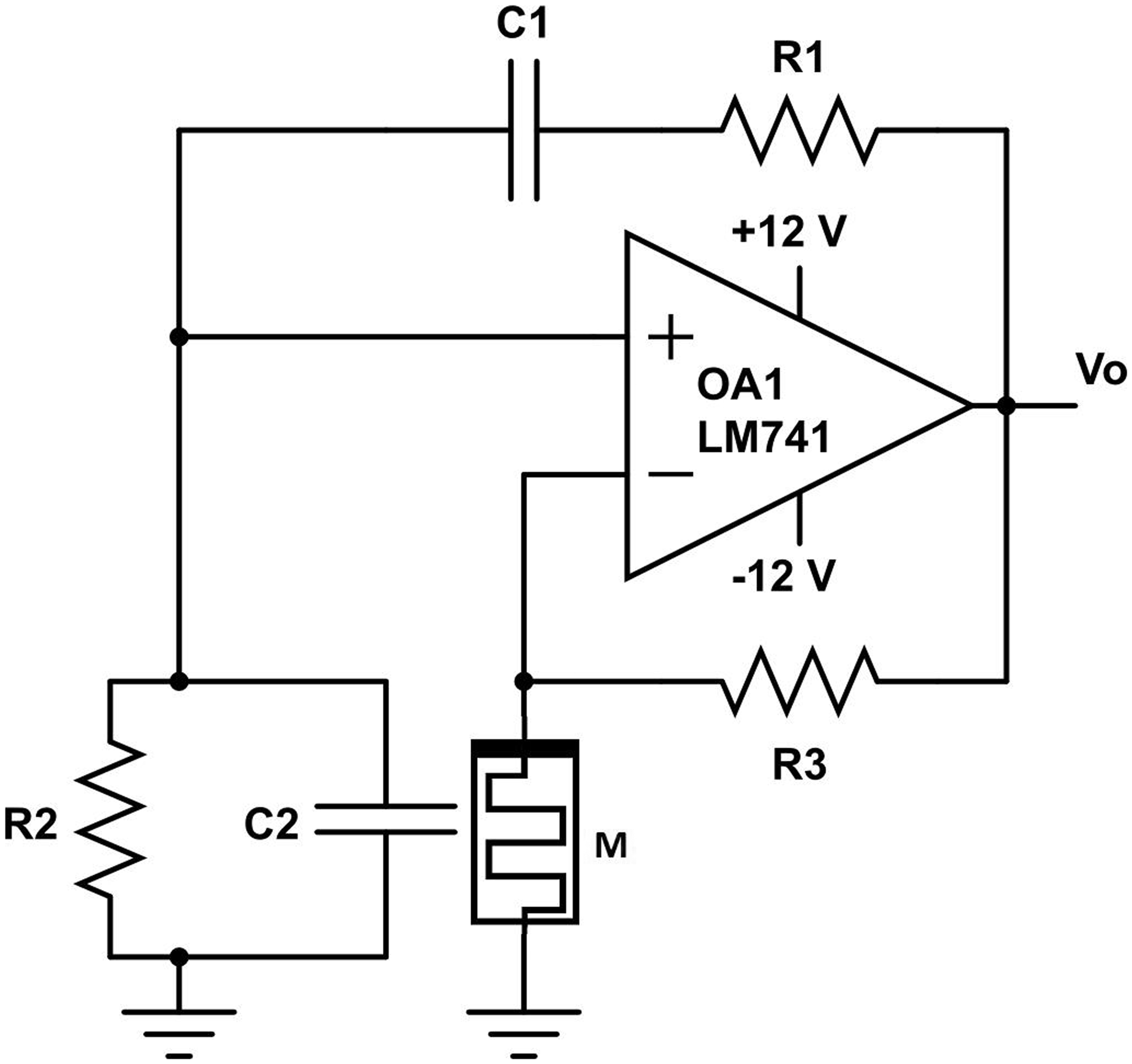


In equations (2) to (4)
Using equation (1), the poles of the oscillator circuit of Figure 1 can be expressed as
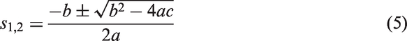
From equation (5), the frequency of oscillation and the condition of oscillation can be expressed as
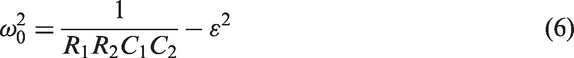


From equations (2) to (8), it is obvious that since the memristor resistance
The performance of the circuit of Figure 1 and its variants as a chaotic oscillator was recently investigated and the results are reported in literature.18–20 However, because of the commercial unavailability of the memristor, the authors in some literature18–20 used SPICE models for verifying the functionality of the circuit of Figure 1 as a chaotic oscillator. Here we propose to examine the functionality of the circuit of Figure 1 using the memristor emulator reported in Abuelma’atti and Khalifa
21
and shown in Figure 2.
Memristor emulator.
21
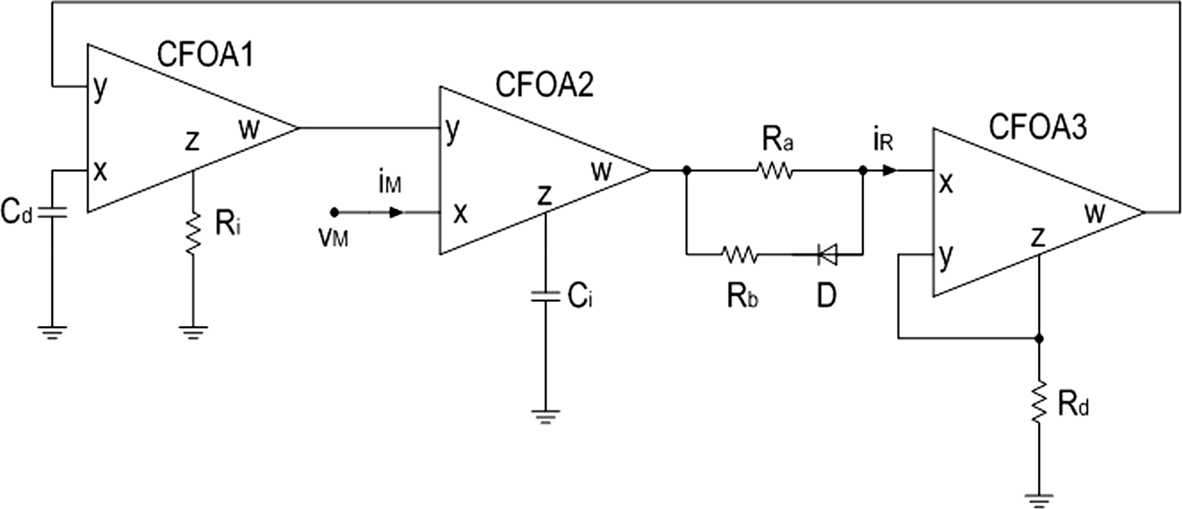
The memristor emulator circuit shown in Figure 2 was implemented using the CFOA AD844, the diode 1N4148 and the capacitors and resistances values given by The current-voltage characteristic of the memristor emulator of Figure 2 at a frequency of 100 Hz. The current-voltage characteristic of the memristor emulator of Figure 2 at a frequency of 700 Hz.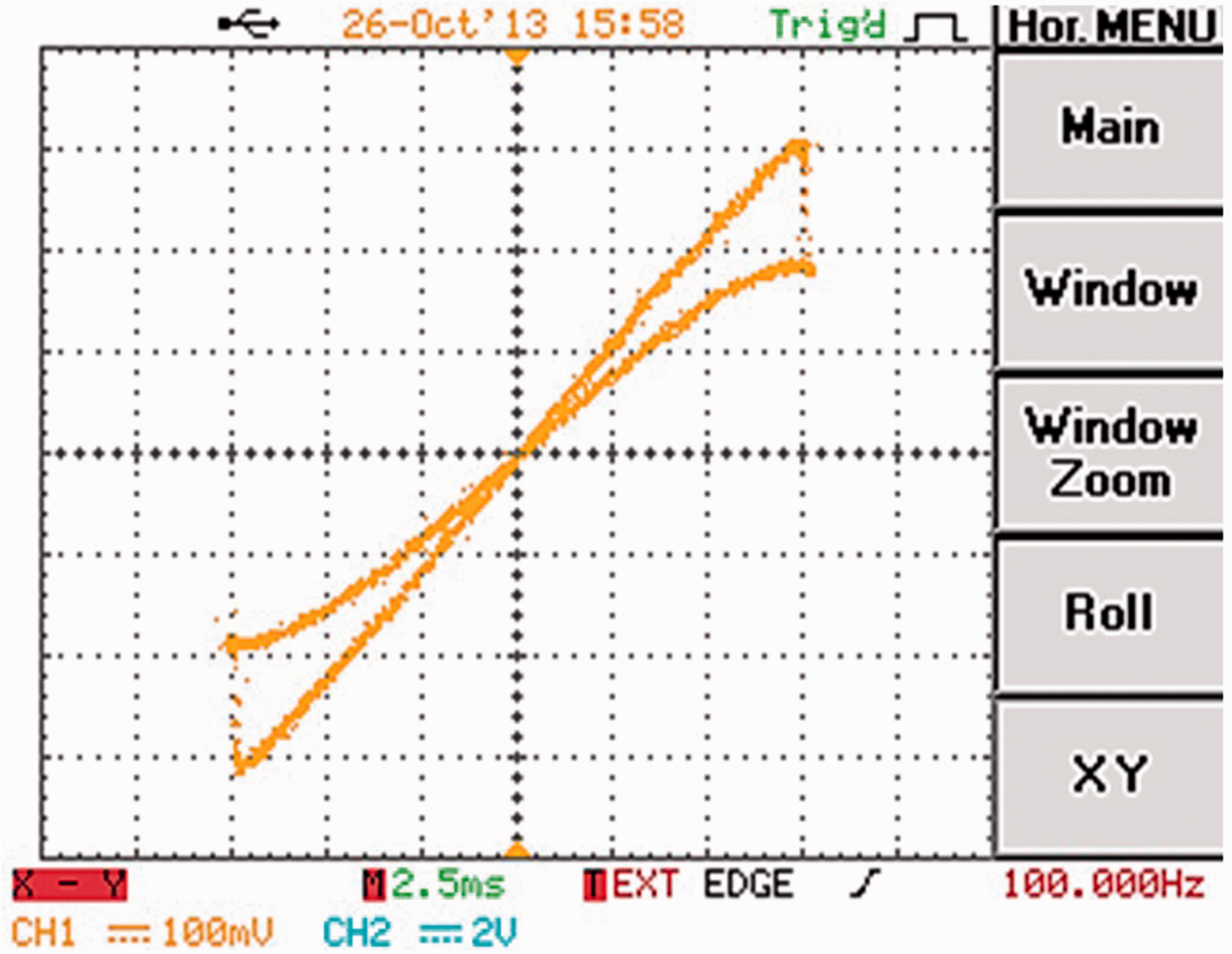

Inspection of Figures 3 and 4 clearly shows that the memristor can bahave as a linear resistance at a frequency of 700 Hz while it behaves as a nonlinear resistance at a low frequency of 100 Hz.
The circuit of Figure 1 was implemented using 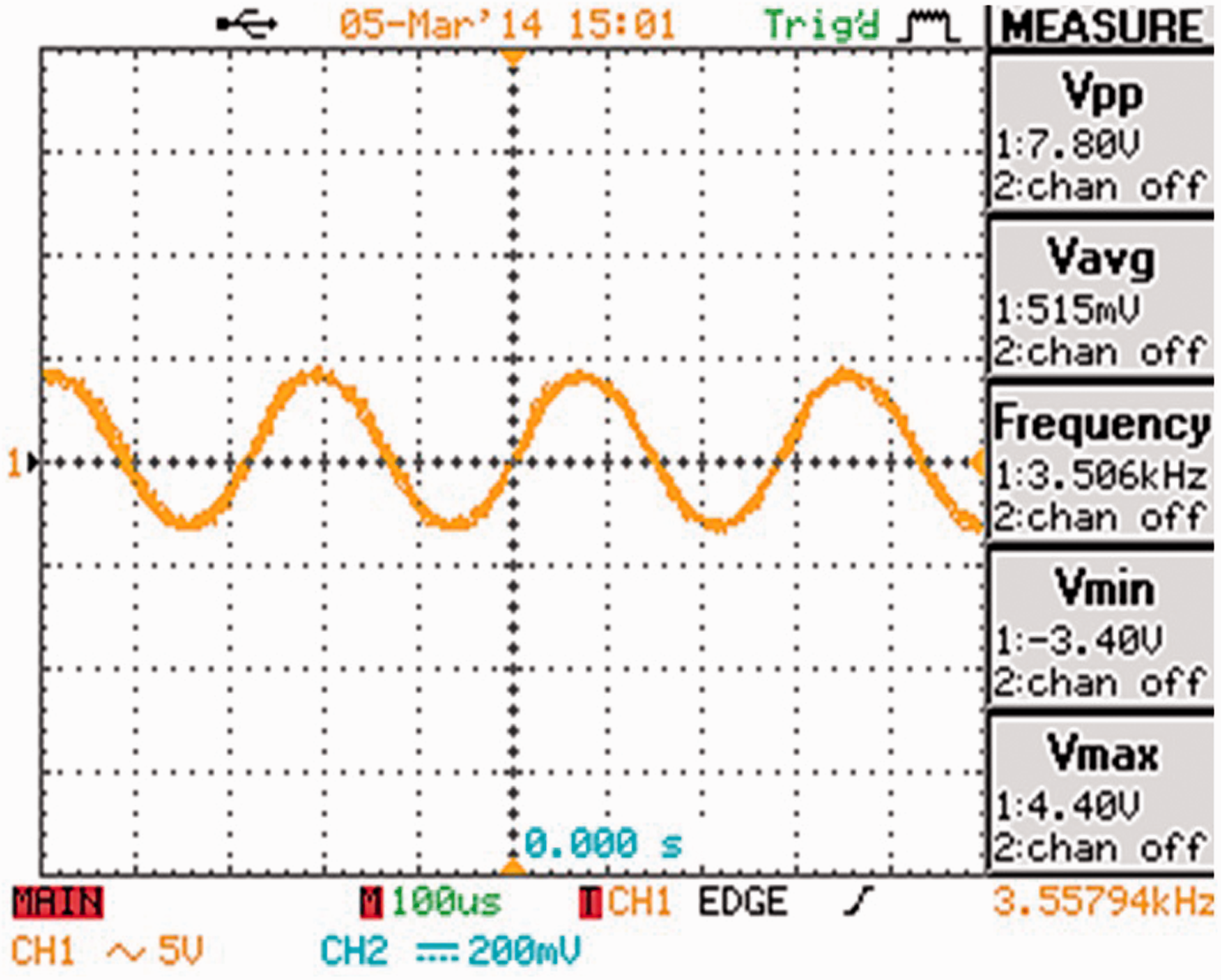
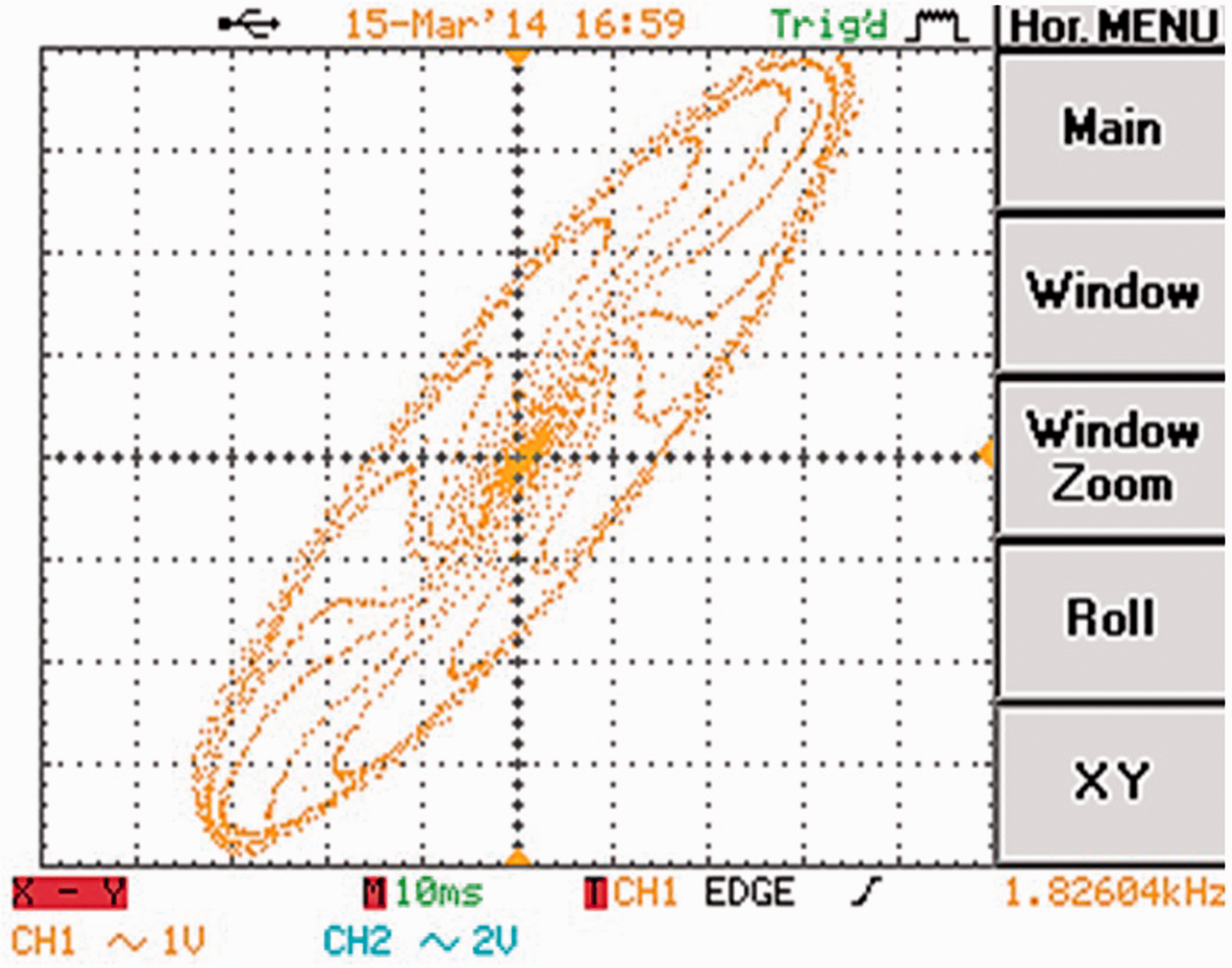
It is worth mentioning here that in Figures 6 to 8, the chaotic behavior of the circuit was demonstrated by probing the voltages at the two terminals of the capacitor C1. Alternatively, the chaotic behavior of the circuit can be equally demonstrated by probing any other two voltages and/or currents in the circuit.
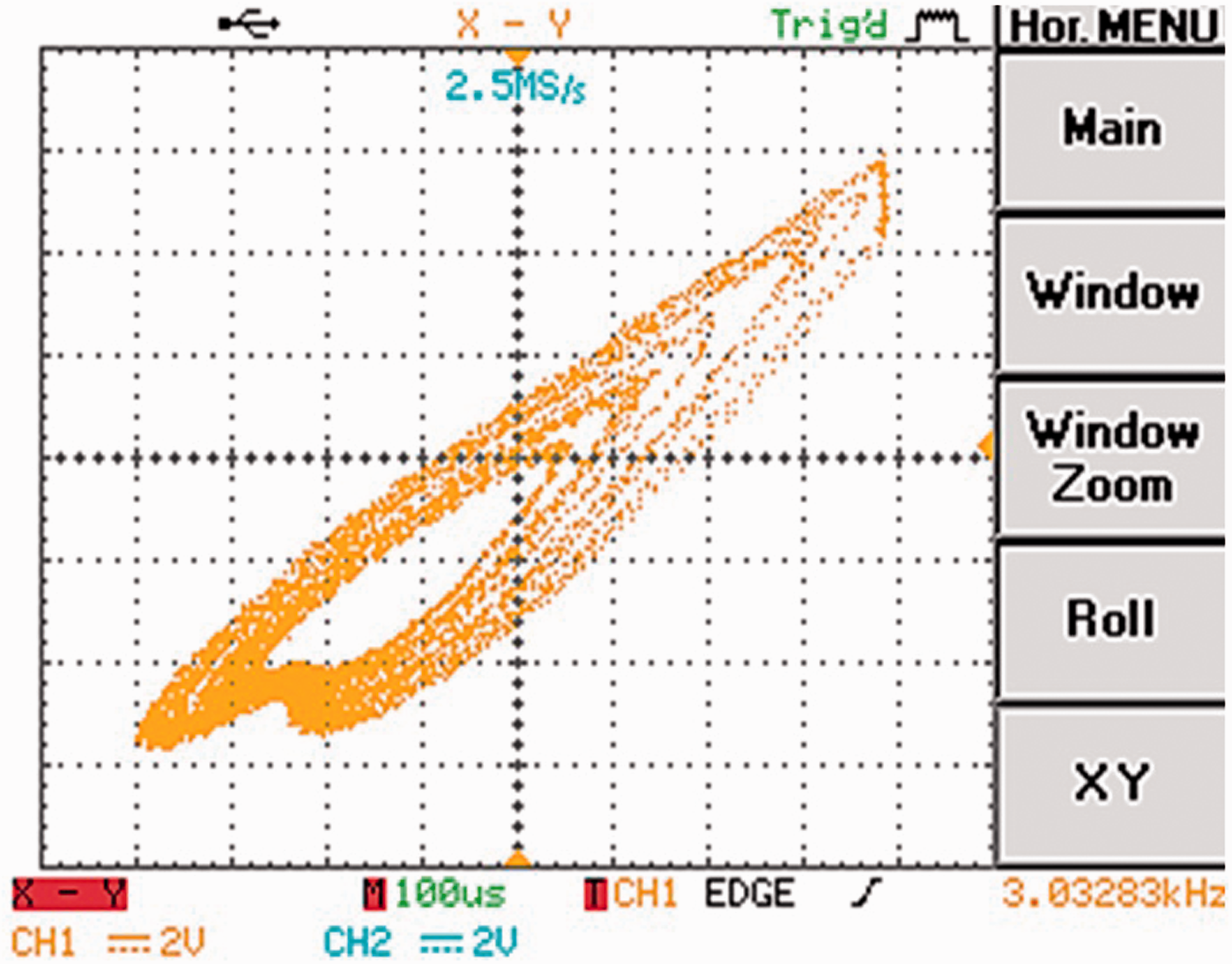
The two voltage waveforms probed from the two terminals of the capacitor C1 of Figure 1. The X–Y representation of the voltages shown in Figure 6. The X–Y representation of the voltages shown in Figure 6 with higher value of R3.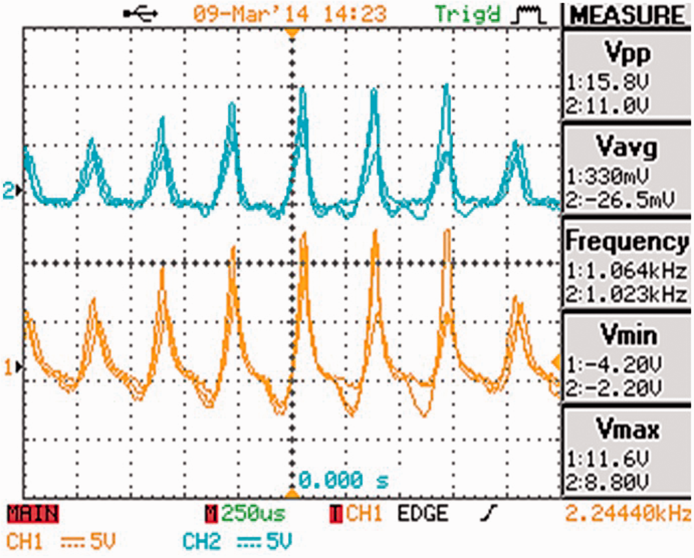
Conclusion
In this paper, it has been shown that the same memristor-based Wien bridge oscillator circuit can provide the nonlinear chaotic or the linear sinusoidal oscillations by varying a single resistance. The memristor emulator used in the experiments can be easily implemented using off-the-shelf components. The results obtained can be easily repeated to show the students in an undergraduate laboratory the performance of chaotic circuits and how they can be moved from the linear sinusoidal operation to the nonlinear chaotic operation.
Footnotes
Declaration of Conflicting Interests
The author(s) declared no potential conflicts of interest with respect to the research, authorship, and/or publication of this article.
Funding
The author(s) received no financial support for the research, authorship, and/or publication of this article.