
Abstract
The main dials of the back face of the Antikythera Mechanism have partially survived together with the pointer of the upper dial and a few remains of the mechanism that supported and rotated it. The reconstruction of this mechanism, described in this article, fits perfectly its description in the Mechanism’s inscriptions. Our results also show that both spirals were Half Circles spirals, drawn from two different centres. The unwanted eccentricity that would be produced from the pointer’s being placed at one of the centres is proven to have been ingeniously avoided with the appropriate drawing of the cell divisions.
1. Introduction
The Antikythera Mechanism, the 2000-year old astronomical computer, has unfortunately not fully survived, its remains being broken into several fragments. 1 Its back face, bearing two main dials, both in the form of spirals, is preserved in Fragments A, B, E and F. 2 Figure 1 shows computer tomography (CT) slices 3 of Fragments A, B, E and F.
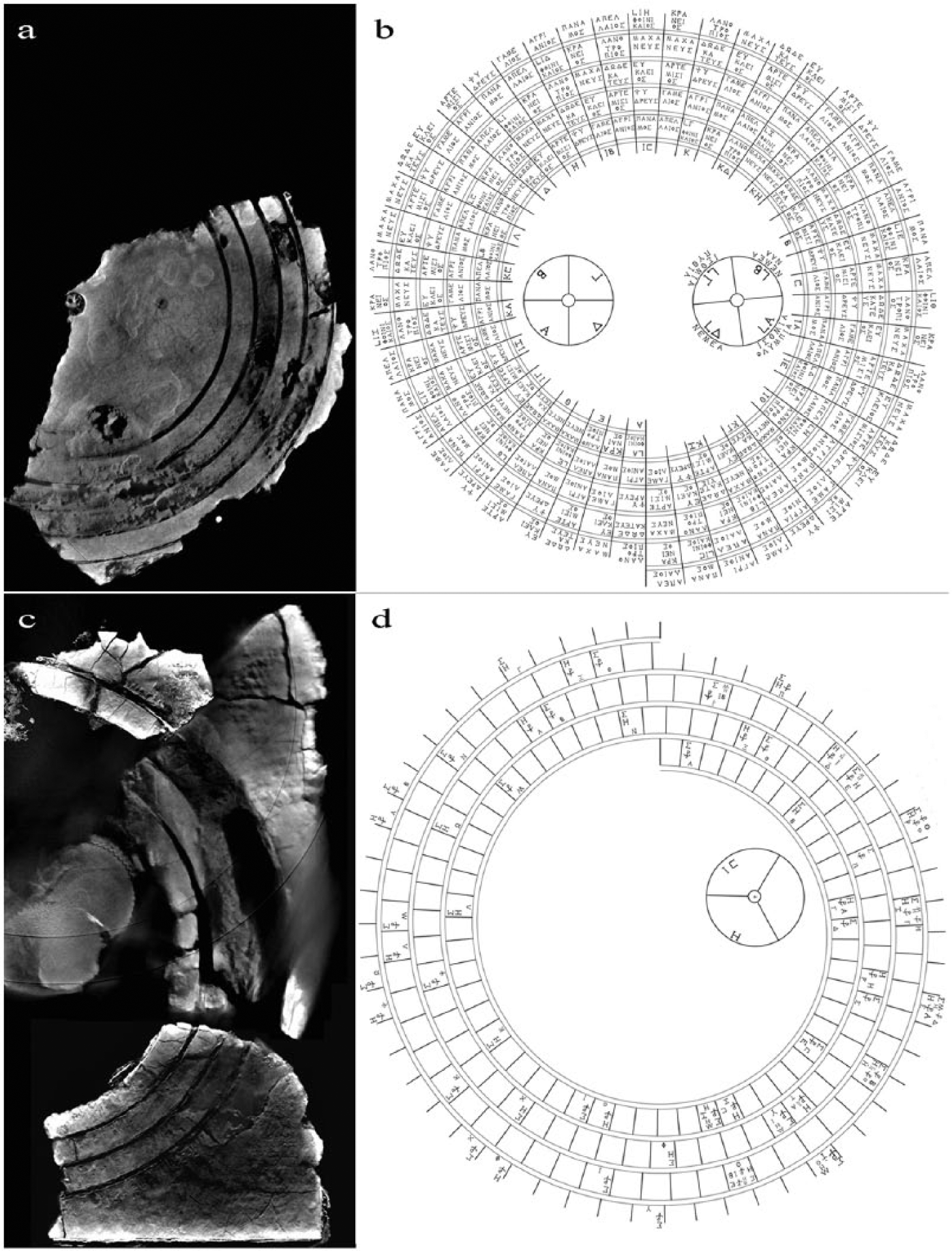
(a) CT slice from Fragment B showing the remaining parts of the Metonic dial. (b) Reconstruction of the Metonic dial of the Antikythera Mechanism. (c) CT slices from Fragments A, E and F showing the remaining parts of the Saros dial. The two thin circular lines on Fragment A are artifacts produced during the scanning of the fragment. (d) Reconstruction of the Saros dial of the Antikythera Mechanism.
The upper back dial had 235 divisions in a five-turn spiral, with 47 divisions per turn that represented a 19-year calendar (235 lunar months) known as the Metonic cycle. 4 The Metonic cycle was equivalent to 12 years of 12 lunar months and 7 years of 13 lunar months (12 × 12 + 7 × 13 = 235) and reconciled remarkably well the solar year with the lunar months. The extra month is called intercalary. Fragment B preserves the surviving part of the Metonic dial (almost one third of it), its centre as well as part of the pointer whose guiding pin moved through the gap between the spiral scales. The last gear transferring the motion to the pointer is missing.
The lower back dial, a four-turn spiral with 223 divisions, displayed the Saros cycle, a periodicity of repetition of solar and lunar eclipses. The 223 divisions represented again 223 lunar months. Some divisions predicting eclipses were marked with inscriptions (glyphs) that described the type (solar or lunar) and time of eclipse to occur on that month. Fragments A, E and F preserve parts of this dial with its centre visible at Fragment A. The pointer of the dial is missing.
Since the last publication dealing with the back dial spirals, 5 two new important inscriptions have been identified by our team. 6 (a) In 2010 the examination of the cells of the Metonic dial led to the identification of ‘MACHANEUS’ (ΜΑΧΑΝΕΥΣ) as the intercalary month of the Antikythera calendar (unlike other calendars that had different intercalary months, it is most likely that the calendar of the Antikythera Mechanism used a single intercalary month (for more information, see Appendix A of the online edition)). More precisely, the name of this month was read in two consecutive cells, cells 128 and 129 (Figures 2(a) and 2(b)). (b) A new division of the Saros dial marked with glyphs, cell 61, was found (Figure 2(c)). This finding increased the number of preserved cells with glyphs from 18 to 19. The reconstructions of the Metonic and Saros dials, presented in Figure 1, include these new findings.
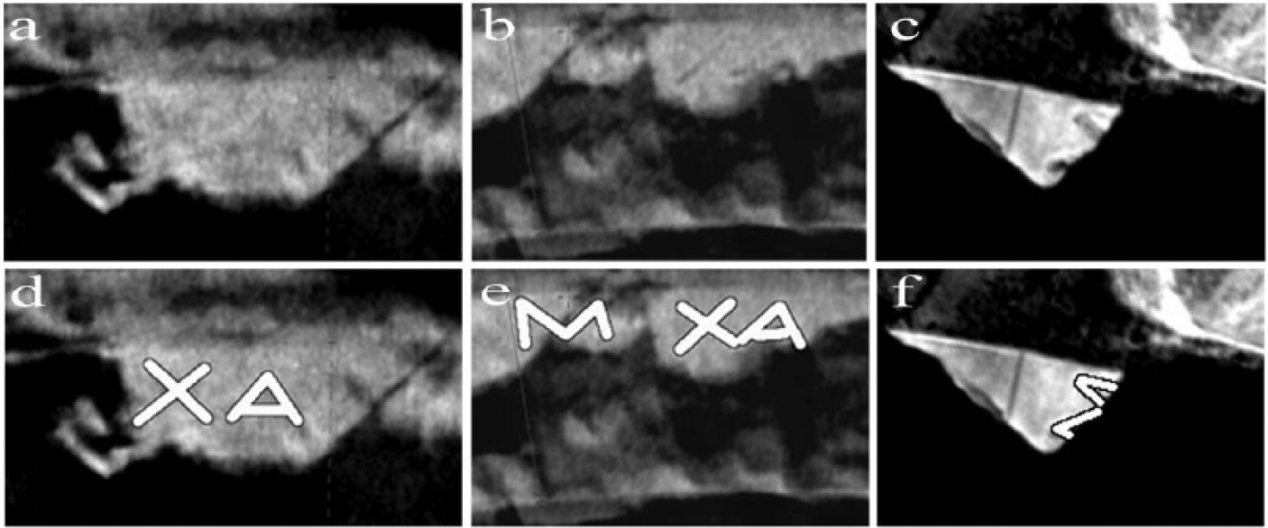
(a) CT slice from Fragment B, Metonic dial, cell 128: month name Machaneus. (b) CT slice from Fragment B, Metonic dial, cell 129: month name Machaneus. (c) CT slice from Fragment E, Saros dial, cell 61, letter Σ (lunar eclipse). (d), (e) and (f) Traces of the letters of the CT slices.
2. The Pointer of the Metonic Dial
2.1. The Physical Remains
The remains of the pointer of the Metonic dial can be seen in Figure 3. Its dimensions are approximately 52 × 4.3 × 2.3 mm 7 or slightly larger. 8 At one end the pointer takes the form of a small vertical rectangular guiding pin that followed the gap of the spiral scales. Right above the guiding pin, a horizontal arrow-shaped cylindrical pin was used for precisely pointing at the divisions of the dial. The pointer is broken at the place where it was attached to the shaft that drove it.
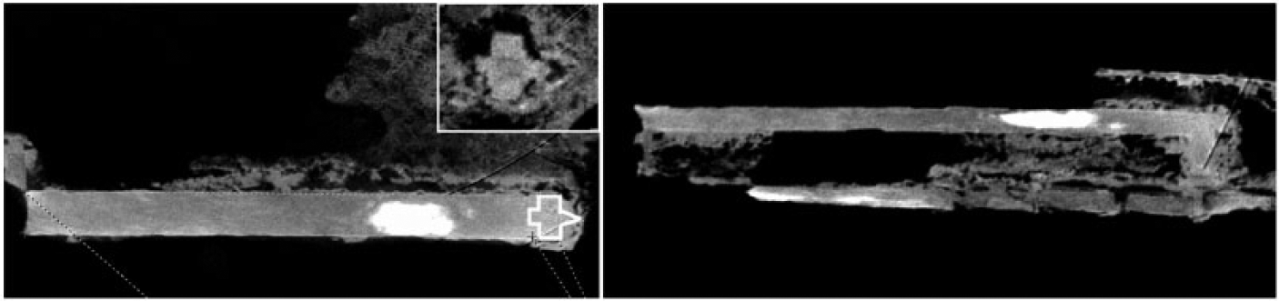
Left: CT slice of the pointer from Fragment B. The white line traces the form of the pointer at the arrow-shaped cylindrical pin, depicted at the inset. Right: Side view of the pointer.
The pointer, partially visible on Fragment B, was first described by Price, 9 who noted that its length was clearly not sufficient to extend from the centre to the outside limb of the upper dial. For Price the back dials were concentric rings, not spirals. The spiral shape was later discovered by Wright. 10 The existence of the guiding pin and its function in following the gap between the spiral scales in order to show the relevant month were identified by Freeth et al. 11 However, their idea that the guiding pin was held on a sleeve, which slid along the pointer, is incorrect. The construction that supported the pointer transferring to it at the same time the rotation of the shaft is badly damaged. However, there are enough remains that allow for the initial arrangement to be reconstructed and they show that the whole pointer actually slid at its hub end. This discovery is surprising, since this clever arrangement of a sliding pointer is not known (to the best of our knowledge) in later history. Figure 4 shows two CT slices of these remains at the hub end.
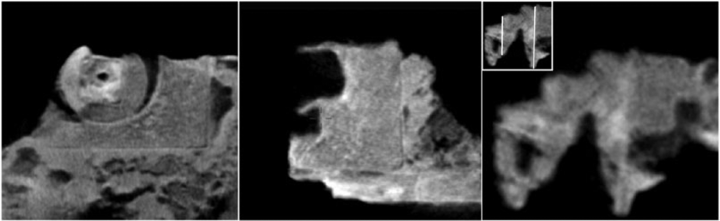
CT slices showing (left) the square-shaped shaft (small complete square), the round head cap and the bottom base (large partial rectangle) of the pointer bracket, (middle) the two holes of one of the sides of the pointer bracket and (right) the remains of the rotating shaft which is broken at the end of the wider middle section of the head cap (the inset shows the same image with white lines tracing the edges of the shaft).
The reconstruction of the entire pointer mechanism is shown in Figure 5. The cylindrical rotating shaft was trimmed to a square-shaped end so that a head cap component could fit on it. The head cap was shaped by three cylindrical segments: a narrow end, a wider middle segment, and an even wider disc. Part of the preserved square-shaped shaft reaches the end of the wider middle section (Figure 4). The disk bore some rather strange formed quadrant cavities whose role is difficult to explain. 12 The circular shape of this disk was cut to two straight parallel vertical surfaces (Figure 5), which fitted to the two sides of a pointer bracket. The pointer bracket had the form of a rectangular base with two orthogonal sides. Only one side is preserved, and in it two holes can be seen. The pointer went through the upper hole which was larger than the lower one. A square shaped pin (today lost) went through the bottom hole as well as the head cap, so fastening the head cap component to the pointer bracket. The role of the pin was crucial: it secured the pointer bracket to the head cap in such a position that the pointer (which slid through the upper hole) could freely follow the full Metonic spiral. The pointer mechanism assembly was probably tightly wedged to the square-shaped shaft (alternatively, if the broken end of the shaft reached the disk, then the assembly would be easily secured to the shaft by the pin). The Metonic pointer could be reset by slightly bending it and sliding it back to the beginning of the spiral. It was probably calibrated once during the construction of the Mechanism as the whole pointer mechanism does not allow for recalibration. 13
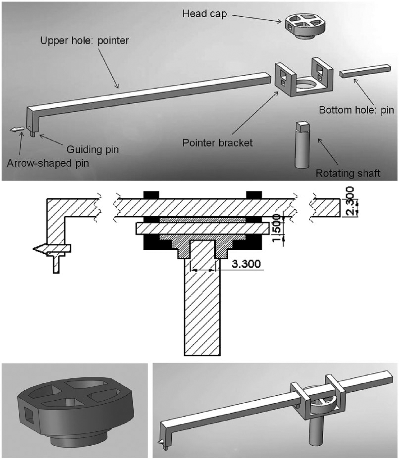
Top: Exploded view of the reconstruction of the pointer mechanism. Middle: Section of the pointer mechanism. Bottom: Closer view of the head cap component (left) and assembled reconstruction of the pointer mechanism (right).
There is another part of the Antikythera Mechanism in which the output was attached to a square-sectioned shaft. This is in the Moon phase device, identified by Wright. 14 The arrangement there was simple: a square-sectioned shaft went through the front plate of the Moon phase cylinder and was held in place by a pin. In the case of the pointer of the Metonic dial, the idea was again to attach the pointer bracket to the rotating shaft, yet a more complicated structure was invented and the head cap was inserted in order to (a) provide a much more stable and secure attachment of the pointer bracket to the shaft, and (b) serve as an extra support of the pointer that facilitated its movement (by taking the form of a disk at its top).
That the pointer mechanism was constructed in such a sophisticated way amazes us. A similar construction is thought to have existed in the Saros dial.
2.2. The Inscription Describing the Pointer’s Construction
The Antikythera Mechanism had a large number of inscriptions covering its front and back faces and covers. These inscriptions have partially survived. In the back cover inscriptions 15 we find several technological construction terms together with terms about astronomical periodic cycles, and it seems that they described some parts of the Mechanism. Part of this inscription can be seen in Figure 6. 16 The phrase “spiral divided into 235 sections” is the key to understanding the description of the Metonic dial. On the following lines we read about “two braces around a disk”, “holes to these braces”, and some parts that “slide through the holes”. This description matches exactly the reconstruction of the pointer mechanism that has just been presented. The braces are the vertical surfaces of the pointer bracket and the disk is the top part of the head cap component. The parts that slide through the holes are most probably the pointer and the pin. The inscription and the physical evidence turn out to confirm each other very nicely. 17
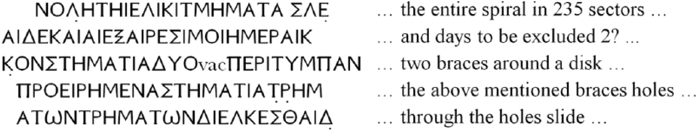
Part of the back cover inscription describing the pointer mechanism, with translation in English. The transcription of the Greek text was made following the Leiden convention.
The back cover inscription probably continued with a few more lines describing the pointer mechanism, but the text as preserved is heavily fragmented.
3. The Type of the Back Plate Spirals
There are two basic types of spirals with constant width between the turns. The first type is the well known two-dimensional spiral with its radius proportional to the angle of rotation, the Archimedean spiral, named after Archimedes (287
3.1. Method Used
For each type of spirals that we examined (Archimedean or Half Circles), the surviving part was divided by drawing a number of almost equally spaced radial lines (Figure 7) that began from either the same or different centres, according to the type under investigation. These lines intersected the gaps between the spirals in two places: the inner gap point and the outer gap point. The intersection points of the radial lines with the spiral gaps were named after the line designation (A, B, C, etc., in clockwise order as the spirals of both dials, Metonic or Saros, unfold clockwise), the gap number (Gap1, Gap2, etc.), and whether the point refers to the inner or outer intersection. In all cases, we measured (a) the length of the radius at each intersection point, and (b) the angle between the line-under-investigation and an arbitrary, chosen line (for the Metonic spiral, the chosen line was line A, whereas for the Saros spiral, the chosen line was line Ι). The above designations become obvious in Figure 7. All radii were measured in millimetres, all angles in degrees (°).
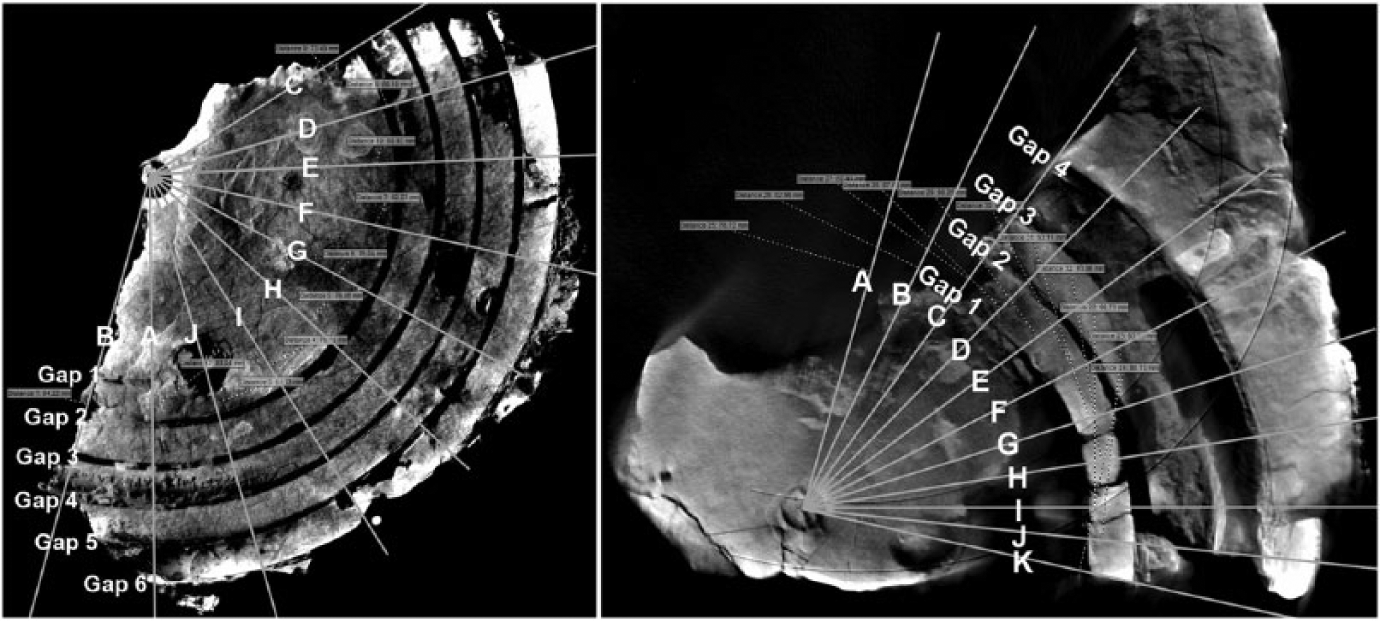
The radial lines and their points of intersection with the spiral gaps for the Metonic (left) and Saros (right) dials. The lines are drawn from the visible centre for the Metonic dial and the pointer centre for the Saros dial.
3.2. The Metonic Dial
On the part of the preserved Metonic dial (Figure 7), the beginning of the spiral and its centre have survived. In the case of a Half Circles spiral, the division line between the two semicircles would be the vertical midline (Freeth et al.
20
), dividing thus the Metonic dial into a left and a right half. For our analysis, 10 radial lines were drawn starting from the (inner) beginning of the spiral (line A).
A close examination of the centre of the Metonic dial (Figure 8) showed that the visible centre (dark spot) does not coincide with the centre of the round hole (hereafter mentioned as the pointer centre, or pc) that was opened on the back plate in order for the shaft of the pointer (see §2.1) to go through. The visible centre was probably violently misplaced after the ship sank. The pointer centre is the centre of the circle that was fitted to the edge of the round hole of the back plate (marked with a ‘+’ in Figure 8).
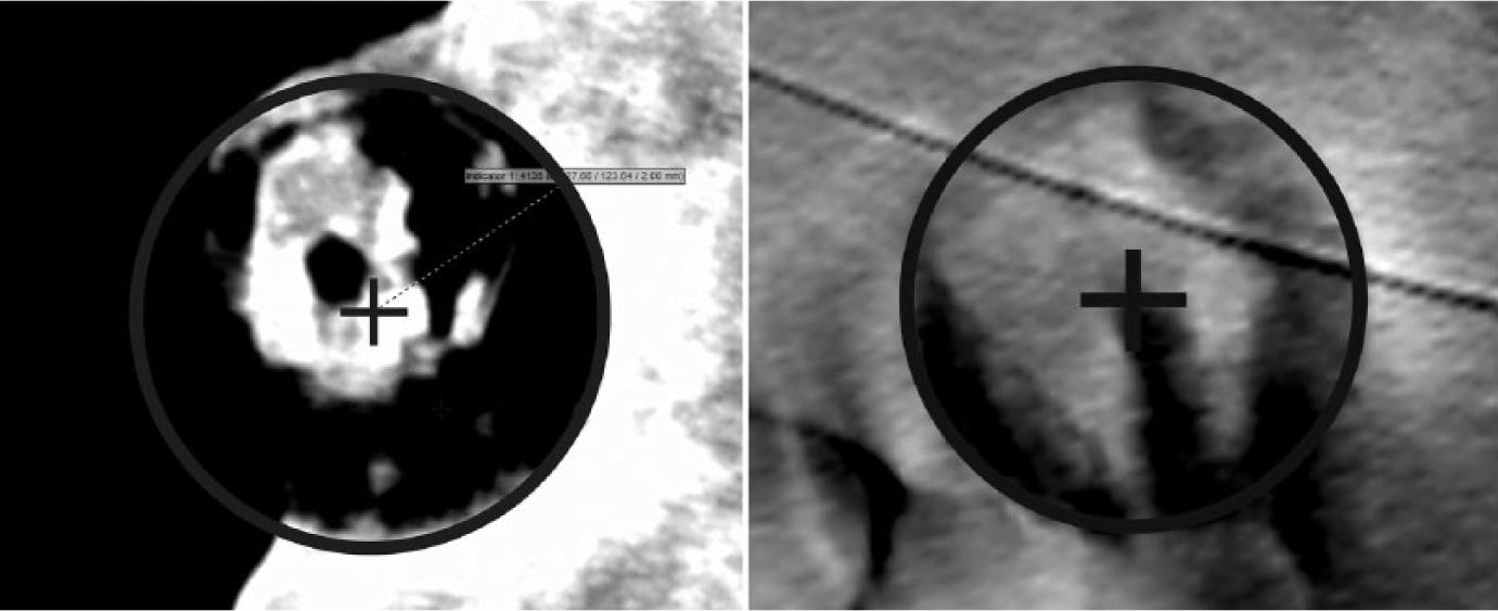
CT slices from the Metonic dial (left) and the Saros dial (right), showing (a) the visible centre (dark spot), (b) the fitted circle, and (c) the pointer centre (the cross).
For each of the cases examined, plots of angle v. radius were made (Figure 9). Each diagram presents the resulting plots for both the inner and the outer spiral gap intersection points. The cases examined were:
An Archimedean spiral, drawn from the visible centre. All lines begin from the visible centre. The plot of angle v. radius shows generally a linear increase of the measurements. At each winding of the spiral though only the first points (C, D, E, F) of the right half of the spiral seem to have positive gradient (slope). The rest of the points have zero or negative gradient while the two points of the left half (A, B) tend to have radii equal to the first points of the right half of the previous winding. The plot does not support the case considered (Figure 9(i)).
An Archimedean spiral, drawn from the pointer centre. All lines begin from the pointer centre. The plot of angle v. radius shows zero gradient (Figure 9(ii)). This indicates the existence of homocentric circles (not a spiral) which would not allow the pointer to follow the full Metonic cycle.
An Archimedean spiral, drawn from a fitted centre. All lines begin from the centre that was determined when an Archimedean spiral was fitted to the remaining spiral. The plot of angle v. radius shows negative gradient which is not consistent with the case of an Archimedean spiral (Figure 9(iii)).
A Half Circles spiral, drawn from the pointer centre and a lower centre. The centre of the left half of the spiral is the pointer centre. The distance of the centre of the right half is taken 3.67mm below the pointer centre. This distance must be half the distance between the windings of the spiral. The radius of line-A_Gap1-inner (see §2.2) is 35.71mm and the radius of line-A_Gap2-inner is 43.09mm, so half the distance between the windings is 3.69mm, while the radius of line-A_Gap1-outer is 37.06mm and the radius of line-A_Gap2-outer is 44.36mm, so half the distance between the windings is 3.65mm. Hence the mean distance between the windings is 7.34mm. The plot of angle v. radius shows that the two points of the left half (A, B) make sharp steps of ~7mm, while the rest of the points show an extreme negative gradient that does not agree with the fixed radii of semicircles (Figure 9(iv)).
A Half Circles spiral, drawn from the pointer centre and an upper centre. The pointer centre is the centre of the right half of the spiral while the left half has its centre at 3.67mm above the pointer centre. The plot of angle v. radius shows two groups of points that succeed each other at intervals of ~3.5mm (Figure 9(v)). The one group is composed of the points of the left half of the remaining spiral (A, B) and the other of the points of the right half (C to J). The exact mean interval between the two groups is 3.69mm, which is very close to 3.67mm (the mean distance between the windings calculated above). This plot shows exactly what it is expected for a Half Circles spiral, thus the plot confirms that the centre of the right half of the Metonic spiral is the pointer centre and the centre of the left half is the upper centre.
A Half Circles spiral, drawn from two centres symmetrically arranged about the pointer centre. None of the centres coincides with the pointer centre: the two centres are symmetrically positioned above and below the pointer centre, at distances equal to 3.67/2 = 1.835mm. The plot of angle v. radius (Figure 9(vi)) is similar to the one in case (iv). The two points of the left half show sharp steps of ~7mm but the points of the right half form lines with negative gradient.
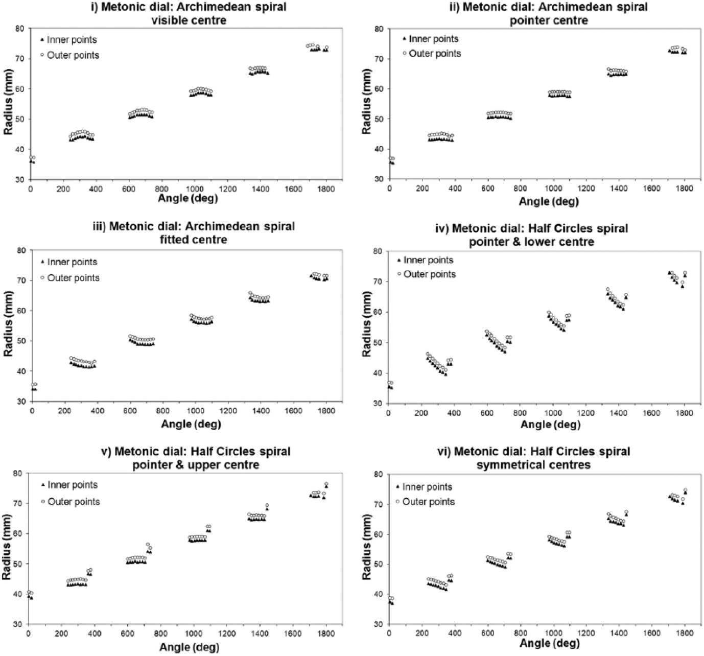
Results of the Metonic dial for all cases considered.
3.3. The Saros Dial
The Saros dial is partially preserved. Remains of it have survived on Fragments A, E and F. The centre of the dial can be seen on Fragment A. A non-perfect placement of the Fragments E and F could result in errors and false conclusions, so only Fragment A was used for the investigation of the construction of the Saros spiral. Fragment A preserves only part of the right windings of the spiral. The state of preservation is however rather poor. Furthermore, the windings seem to be not equally spaced and the spiral is probably quite distorted. Consequently the measurements are less accurate compared to the ones of the Metonic spiral.
The visible centre is very close to the pointer centre. Therefore measurements were made only for the pointer centre. The plots of angle v. radius for each of the cases examined are shown at Figure 10. We examined the following cases:
An Archimedean spiral, drawn from the pointer centre. All lines begin from the pointer centre. The plot of angle v. radius shows a linear increase of the measurements (Figure 10(i)). The spiral however cannot be an Archimedean as most points diverge significantly from the fitted linear trend-lines added to the plot.
A Half Circles spiral, drawn from the pointer centre and a lower centre: the centre of the left half of the Half Circles spiral is the pointer centre and the right half has its centre at about 4.5mm below the pointer centre. The distance of 4.5mm is half the calculated mean distance between the windings of the spiral (which is ~9mm). The plot of angle v. radius confirms that the centre of the right half of the Saros spiral is the lower centre and the centre of the left half is the pointer centre (Figure 10(ii)). The fitting of a trendline does not exclude an Archimedean spiral, but it would be strange and possibly even not practical to construct such a spiral from a centre other than the pointer centre. The results are not as clear as for the Metonic dial, as in this case we have no measurements of both halves of the spiral. Furthermore, as was mentioned above, the measurements are less accurate due to the rather poor condition of the dial. The exact lower centre could possibly be slightly off the pointer centre and the increasing slope of the inner and outer 3rd and 4th winding, seen at the plots, could possibly be due to this non-exact placement of the lower centre.
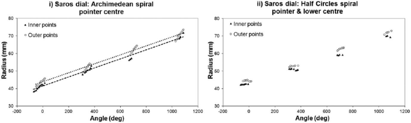
Results for the Saros dial for all cases considered.
4. The Divisions of the Cells
The placement of the pointer and its rotation around one of the two centres of each spiral would result in producing some eccentricity in the readings of the pointer in half of the spiral (whose centre does not coincide with the pointer centre). We call this the eccentricity problem. Taking into account the radii of the windings and the distance of the two centres of each spiral, it can easily be calculated that the eccentricity problem reaches a maximum of 0.67 and 0.90 divisions for the Metonic and the Saros dial respectively. The effect of this problem would obviously be very significant.
The simplest solution for the maker of the Antikythera Mechanism, in order to avoid the eccentricity problem, would be to draw the divisions of the cells in such a way so that they all point to the pointer centre. The analysis that follows checks this hypothesis for both the Metonic and the Saros spiral. Two methods of investigation were applied: (a) by taking into account the centres and measuring the angles of the divisions (for the fragments that preserve the centres, namely Fragments B and A), and (b) by using the preserved part of the spiral in order to find the centre of the windings and the centre of the divisions (for the fragments that preserve only part of the spiral). Both methods conclude that the cell divisions of both spirals have indeed been drawn so that they all point to the pointer centre. Measurements of the length of the chords of the cells, which should gradually become wider as we move clockwise along the winding whose centre is not the pointer centre, independently confirmed this result.
4.1. Investigation of the Metonic and Saros Spirals Taking into Account Their Centres and Divisions
For each spiral we carefully measured two angles. (a) The angle between the first cell division line (i.e. the one coinciding with the vertical midline) and all other clearly visible division lines of the spiral. The vertex of this angle was the pointer centre and it will be referred to hereafter as the pc angle. (b) The similar angle whose vertex was the second centre (thus the upper one for the Metonic dial and the lower one for the Saros dial). This angle will be referred to hereafter as the uc angle for the Metonic dial and the lc angle for the Saros dial. All angles were measured in degrees (°). These angles were compared with the ideal incremental constant angle of the equidistant (i.e. of equal width) cell divisions, calculated knowing (a) that for the Metonic dial the 235 divisions correspond to 5 × 360° (i.e. 7.65957° per division), and (b) that for the Saros dial the 223 divisions correspond to 4 × 360° (i.e. 6.45740° per division). This angle will be referred to hereafter as the ideal angle. For the Metonic dial, we used CT slices of Fragment B and for the Saros dial the PTM (Polynomial Texture Mapping) 21 image of Fragment A. In order to locate the centres of the two spirals, all images were calibrated using VGStudio Max 2.0 measurements of Fragment B (for the Metonic dial) and Fragment A (for the Saros dial). Division line 1 was always the first line of each dial and angles were measured clockwise.
4.1.1. The Metonic back dial
Almost three-quarters of the right half of the Metonic Half Circles spiral is preserved, whereas only a small part of the left half has survived (too small for this analysis). As was shown above, the right half was drawn from the pointer centre (Figure 7). In the analysis that follows we shall examine whether the centre determined by the right half cell divisions is indeed the pointer centre. The cell divisions used for the calculations were from 32 to 50. The division line 40 was excluded as it was not clearly visible. Table 1 presents the three angles mentioned in the previous paragraph for divisions 32 to 50.
Ideal, pc and uc angles for the Metonic dial.
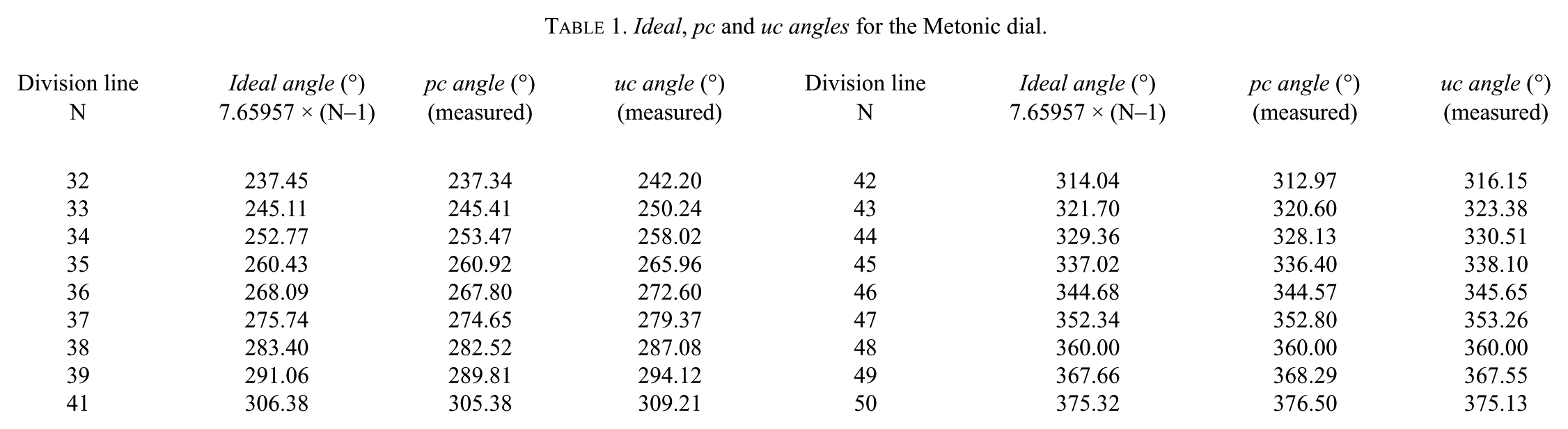
In Figure 11 (left panel) we present the plot of the aforementioned angles v. the cell division number. It is obvious that the pc angle follows closely the ideal angle, whereas the uc angle shows systematic deviations. The deviations become even clearer if one plots the differences between the ideal angle and the pc or the uc angle, i.e., the error in angle from both centres (Figure 11, right panel). It is immediately obvious that the gradient of the error for the pc angle is practically 0, but this is not the case for the uc angle. Therefore the centre determined by the cell divisions of the right Half Circle of the Metonic spiral is the pointer centre, which lies below the second centre.
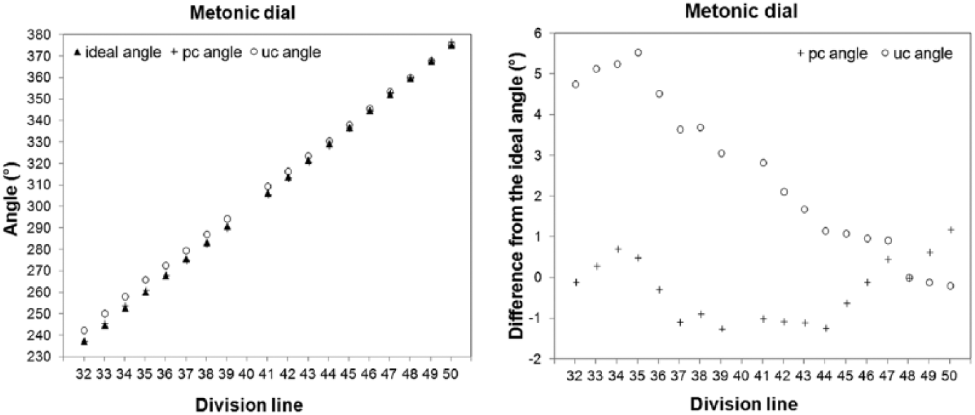
The Metonic dial. Left: Plot of the ideal, pc and uc angles v. the cell divisions. Right: Plot of the differences of the pc and uc angles from the ideal angle.
4.1.2. The Saros back dial: Analysis using Fragment A
Almost the entire right half of the Saros Half Circle spiral is preserved in Fragments A, E and F. Νo part of the left half has survived. As shown above, the right half was drawn from the lower centre (lc). So, for this dial we shall examine whether the convergence centre determined by the right half cell divisions is also the lower centre or the pointer centre.
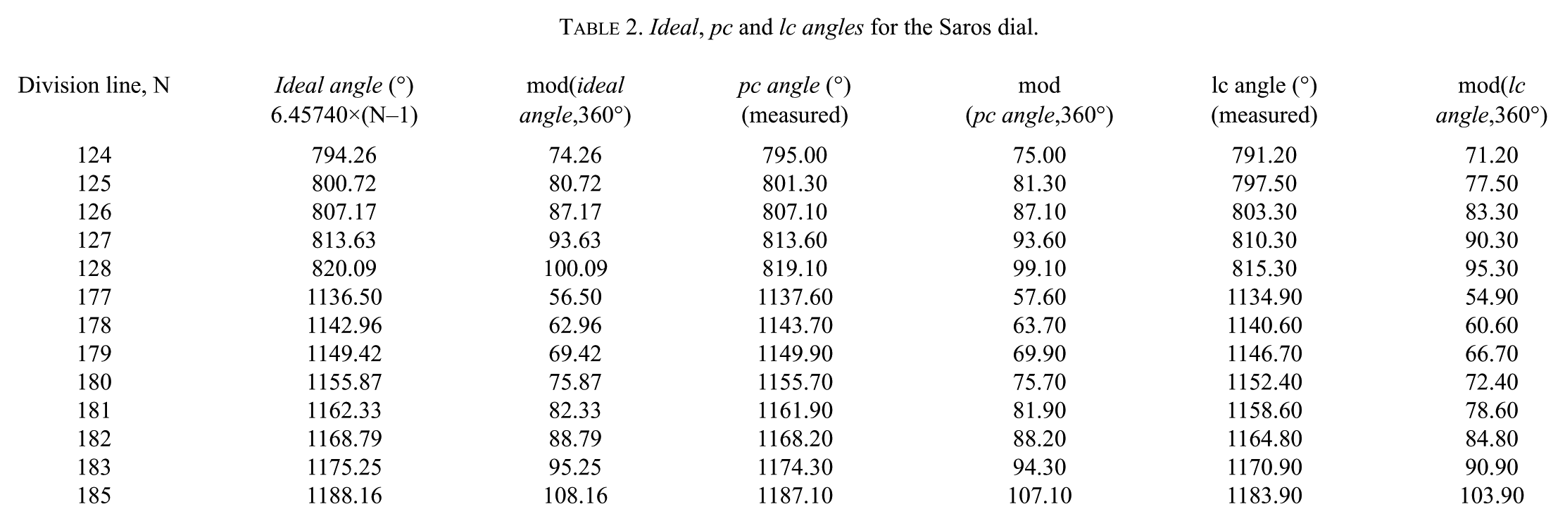
As we worked with the PTM image of Fragment A, we used only the cell divisions that were visible on its surface. Table 2 presents the aforementioned angles that were measured and calculated for cell divisions 124 to 128 and 177 to 185. For the plots of Figure 12, the mod function, mod(angle, 360°), for the ideal, pc and lc angles was used — without the multiples, N*360° of the windings — (Table 2). Division line 184 was excluded as it is not visible.
Ideal, pc and lc angles for the Saros dial.
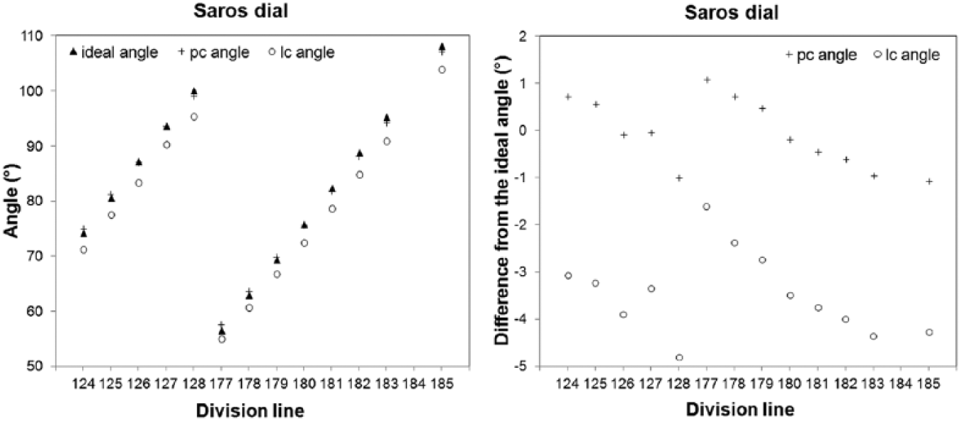
The Saros dial. Left: Plot of the ideal, pc and lc angles v. the cell divisions. Right: Plot of the differences of the pc and lc angles from the ideal angle.
The pc angle values being closer to the ideal angles than the lc ones confirms the hypothesis examined, i.e. that the convergence centre of the cell divisions is the centre of the pointer, ensuring that no eccentricity was produced in the readings.
4.2. Investigation of the Saros Spiral Taking into Account its Divisions
4.2.1. Analysis using Fragment F
The CT scans of Fragment F revealed a very well preserved part of the Saros dial that fitted nicely to the right edge of Fragment A and provided almost an extra quarter of the spiral, almost completing, with Fragment E, the right part of the Half Circle spiral. Fragment F preserves also the right bottom edge of the back plate, which facilitates very well the correct orientation of the preserved part of the dial. As the centre of the Saros dial is in Fragment A, two methods of analysis had to be applied to Fragment F (whose centre is the lower centre (lc)) in order to check whether the cell divisions were drawn from the lower centre or not: (a) one that determined the centre of the windings, and (b) one that determined the centre of the cell divisions. A two-fragment analysis, i.e. an analysis that would fit Fragment A and Fragment F and would then use the centre of the dial, preserved on Fragment A, was avoided as such an analysis involves uncertainties as to how exactly the two fragments fit (rotation, scale, and position would have to be taken into account). Moreover, the windings at Fragment A are somewhat damaged, making the fitting even more imprecise.
For both methods, an image stack of the CT scans of Fragment F was used. The origin of the coordinate system in both cases was the upper left corner of this image stack and the analysis was performed with all values referring to the image size. The values cited in the paper refer to Fragment F and are the ones that were found after calculating the scale factor between the image stack and Fragment F.
(a) The centre of the windings
In order to find the centre of the circular windings, the (xi, yi) coordinates of Ni well-spaced points (approximately 5 for each winding) were determined.
Using these values and applying the iterative Solver method,
22
provided by Excel, the centre of the windings of Fragment F was found to be at the position wc1 = [47.13mm, 35.39mm]. The variables for the Solver method were the (xwc, ywc) coordinates of the lower centre and the radii of the windings (rw). The position of all points (i) was determined using the centre (xi,w –xwc, yi,w –ywc). The points of same winding were naturally set to have the same radius (rw) (as it was proven in §3) and the error was calculated by the formula
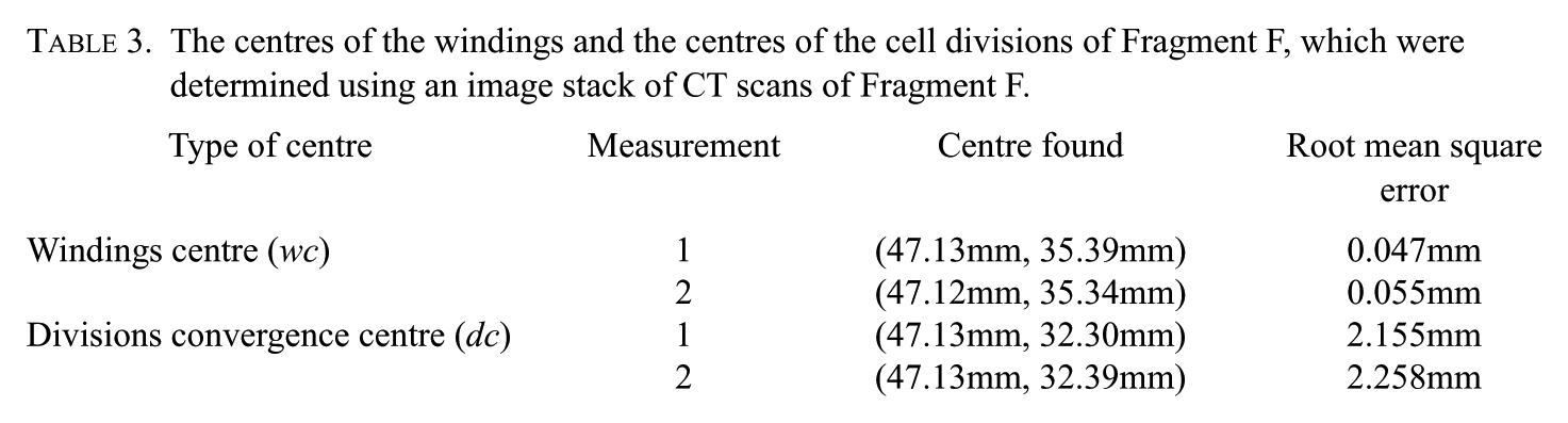
The analysis was repeated again with a new set of coordinates and the new centre that was found was wc2 = (47.12mm, 35.34mm), very close to the previous one, confirming that the method is basically correct. The root mean square error after the application of the method was 0.055mm. Table 3 summarizes the centres of windings that were found.
The centres of the windings and the centres of the cell divisions of Fragment F, which were determined using an image stack of CT scans of Fragment F.
(b) The centre of the cell divisions
Using the same image stack, the convergence centre (xdc, ydc) of the lines of the divisions was determined by applying again the Solver method. The exact points that were used were the points where each division line intersected the outer part of the gaps. Two different sets of measurements were used so that the results could be compared. The division lines that are missing from the second set of coordinates are those with a rather poorly determined intersection point.
Using the first set of measurements, the convergence centre of the cell divisions was found at the position dc1 = [47.13mm, 32.30mm], while with the second set it was found at dc2 = [47.13mm, 32.39mm] (Table 3). The xdc coordinate was set to be equal to the already determined xwc of the centre of the windings, as both centres should be on the vertical midline (using the right bottom edge of the back plate, our set of pictures was vertically-oriented).
The variables for the Solver method were the (xdc, ydc) coordinates of the convergence centre of the division lines. The position of all division lines (i) was again determined using the centre (xi–xdc, yi–ydc) and the error was calculated by the formula
The root mean square error that was found was quite large (around 2.2mm). Plotting the error for each division line, we got the upper graph in Figure 13 which shows that the large errors come from the cells at the end of each winding. Calculating the angular width (lower graph in Figure 13) of the cells of Fragment F (by measuring the length of the chords of these cells and using the mean radii of the windings that were found in Section 3), it becomes clear that these cells (mainly cells 25, 81, 136 and 192) are wider than the others cells of the dial. As Fragment F seems wholly undistorted, the plots of Figure 13 probably reflect an unintentional error of the craftsman 23 who inscribed the division marks. 24 We reapplied the Solver method again after omitting the errors of these division lines. The new centres were found to be at (47.13mm, 31.91mm) and (47.13mm, 31.93mm) respectively, which are very close to the previous found centres (so the convergence centre is not affected), and the root mean square errors were much smaller (around 0.7mm).
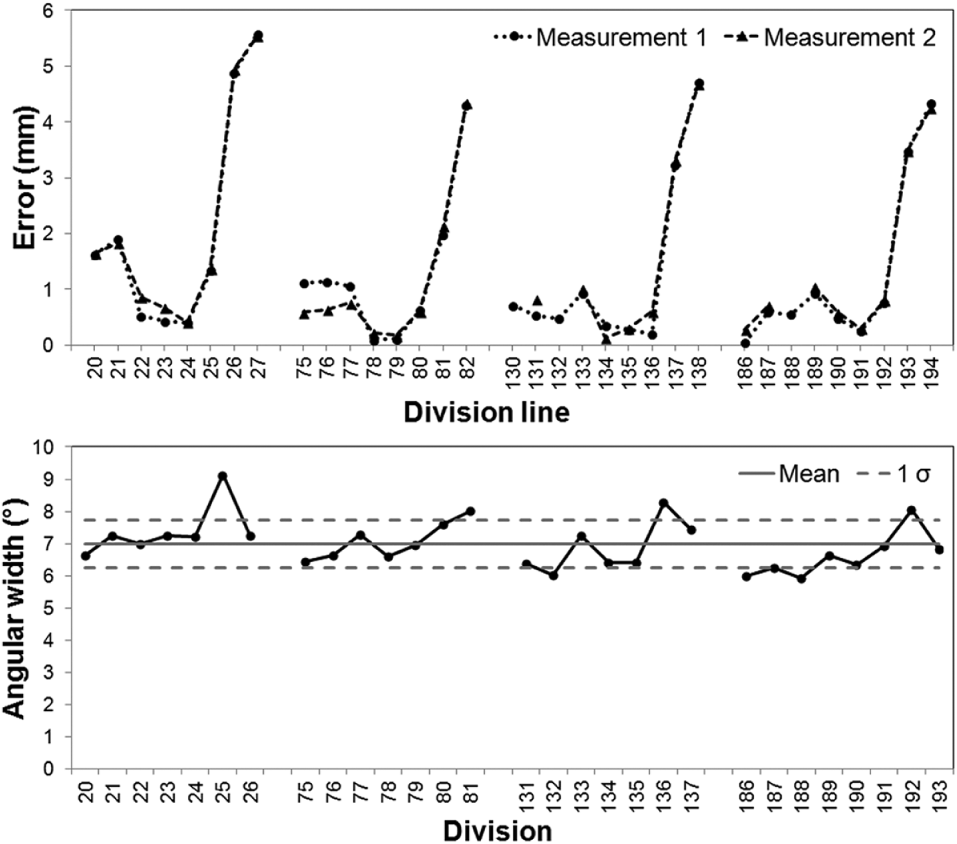
Plot of the error of each division line of Fragment F, for both sets of measurements (top) and plot of the angular width of the divisions of Fragment F (bottom). (Note that the numbers in the upper graph refer to the division lines with division line 1 being always the first line of each dial, while the numbers in the lower graph refer to the divisions with a division N extending from division line N to N + 1. Note also that the upper graph reflects the error of each division line from the calculated dc centre and that is why more cells (compared to the ones of the lower graph) seem to be problematic.)
(c) The distance between the two centres, wc and dc
Figure 14 shows one of the slices of the image stack that was used for the analysis described in §4.2.1(a) and §4.2.1(b) of Fragment F together with the two centres, wc and dc, (indicated at the upper left corner) that do not coincide. The centre of the division lines, dc, is 35.39 – 32.30 = 3.09mm above the centre of the windings, wc. This distance is almost equal to half the distance between the gaps of the windings, as it can be seen in Figure 14, where we placed the symbols (○ and +) marking the two centres next to (a rotated image of) the windings of the Saros spiral (top inset of Figure 14). The centre of the division lines, dc, thus coincides with the pointer centre and so the eccentricity problem is avoided.
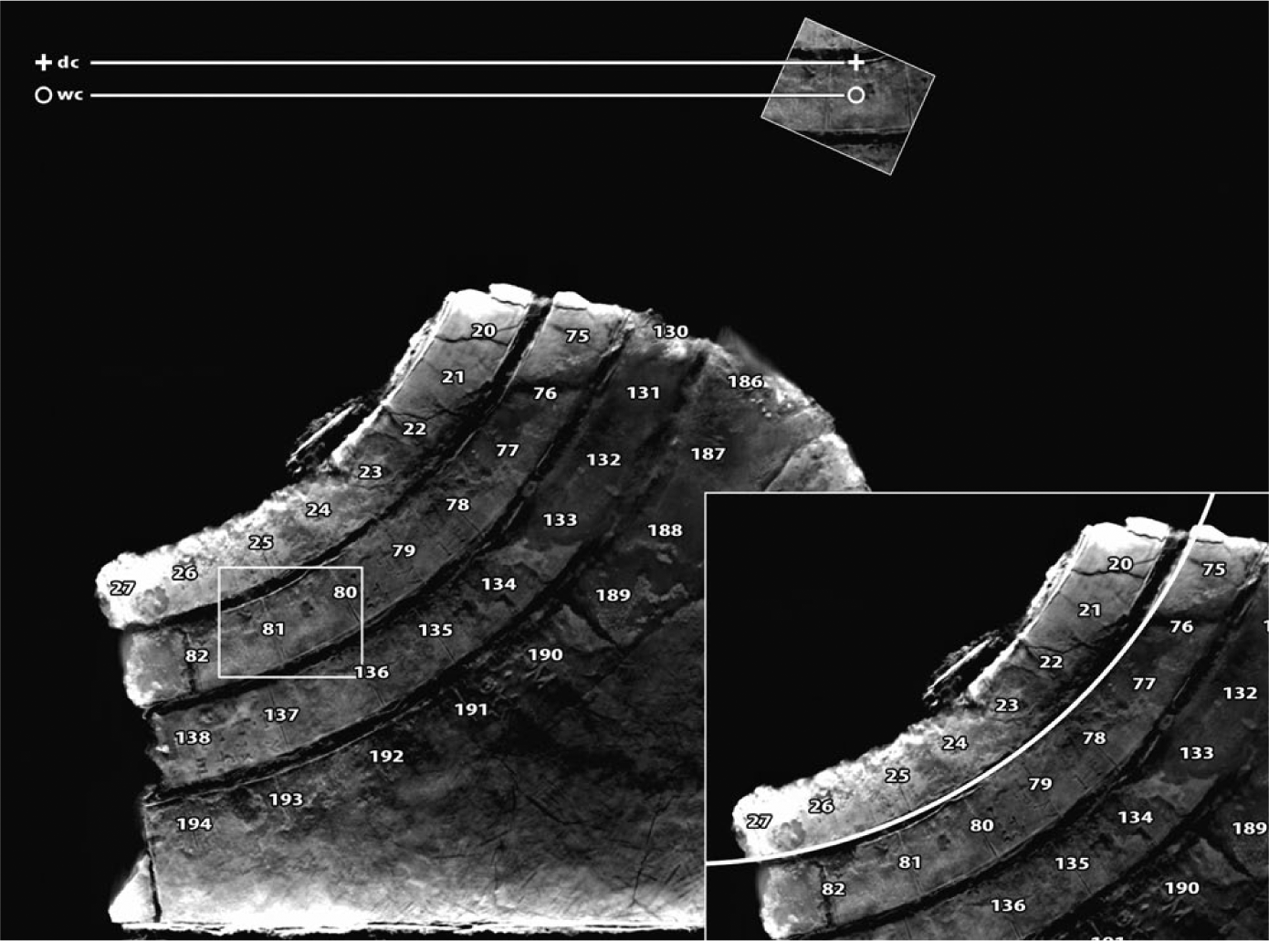
Part of the Saros dial preserved in Fragment F, annotated with the division numbers. The inset above shows a detail of the spiral, rotated so that part of the windings becomes horizontal. The symbols indicate the position of the windings centre (wc, ‘+’) and divisions centre (dc, ‘o’). It is evident that the distance between the two centres (wc and dc) is almost exactly half the distance between the windings. The image is cropped so the origin of the coordinate system (at the upper left corner of the image stack) is not visible. The inset below shows how a circle drawn from the centre of the division lines does not fit the curvature of the windings.
The distance of 3.09mm is quite different from the mean distance of 4.5mm (half the distance between the gaps of the windings) that was found in §3.3. As explained in Appendix B of the online edition, there seems to be a difference between the calibration of the two fragments when they were scanned in 2005. Half the mean distance between the gaps of the windings as measured on Fragment F with VGStudio Max is approximately 4.0mm. The distance of 3.09mm found above is quite close to the mean distance of 4.0mm, as it is also indicated by the image evaluation of Figure 14.
If the centre of the windings coincided with the centre of the division lines then a circle drawn from the centre of division lines, dc, should fit the edge of a gap at all points. The inset at the bottom edge of Figure 14 shows that this is clearly not the case.
4.2.2. Analysis using Fragment E
The poor state of Fragment E prevented us from applying an analysis similar to that applied to Fragment F. As can be seen in Figure 15, Fragment E is broken into 4 main pieces with just 2–3 division lines in each piece. Only the upper right piece that has some lines of text written on it could be orientated correctly. However, only two division lines are preserved on it, a very small number for any analysis.

CT slice of Fragment E showing the four broken parts. At the upper right part of the fragment, two division lines as well as some text can be seen.
4.3. The Length of the Arcs of the Cells
The use of the pointer centre for the drawing of the cell divisions of those windings designed from another centre (in this case, the lower centre) would result in differences of the cells arc lengths and angular widths. The geometry of the construction of the right half of the Saros spiral from the lower centre with cell divisions pointing to the pointer centre theoretically would result in cells gradually becoming wider as we move clockwise along the winding, as Figure 16 shows (in this image, for clarity and simplification, each semicircle was divided into 6 arcs (and not (223/4)/2 ≈ 28 arcs)). The equal arcs of the cells of a circle, drawn from the pc (i.e. the left semicircle and its mirror image (double-dash line) to the right side) can be calculated from equation:

where θ (in °) is the corresponding central angle of each arc and R2 is the radius of this circle, while the increasing values of the arcs of the cells of the first right semicircle, drawn from the wc but converging to the pc, can be calculated from the following equation:

where R1 is the radius of this (semi)circle. The above equation can be easily derived by setting the origin (0,0) to the pc and by defining the equations of the two (semi)circles (C1 for the right semicircle and C2 for the left semicircle) as follows:

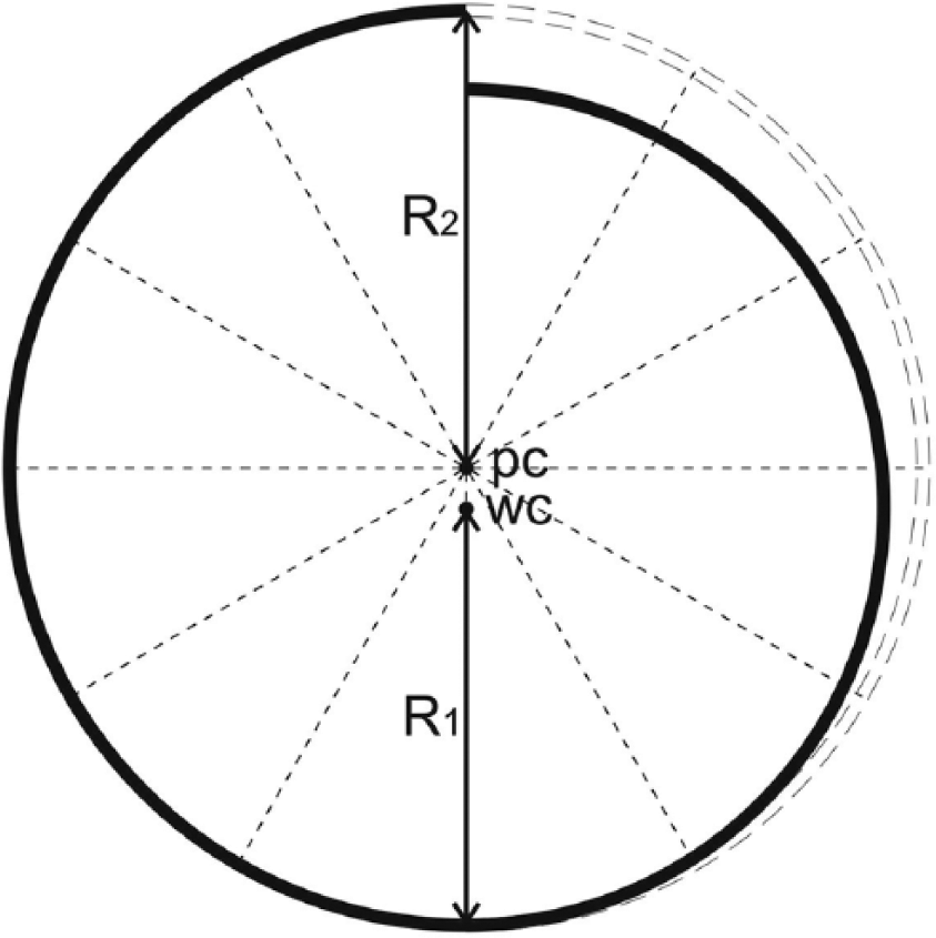
A Half Circles spiral showing the equally spaced arcs (bold left-half and double-dashed right-half) from the pointer centre (pc) and the unequally spaced arcs (bold right-half) from the windings centre (wc).
Measurements of the chords of all clearly visible cells were also made so as to check the above anticipated effect that would independently corroborate our result of the analysis of §4.1 and §4.2.1. We should note that due to the small angle of each division (of the order of 6.6°) the length of the chords is slightly smaller than the length of the corresponding arcs. For the Metonic dial, only the length of the chords of the 1st winding was measured as the chords of the rest of the windings are proportional to the ones of the 1st winding. All chords were measured from their points of intersection with the outer part of the gap. Figure 17 shows the plot of these measurements for both spirals. The arcs of the right Saros windings of Fragment F and Fragment A show clearly a general linear increase (visible also at the bottom plot of Figure 13), unlike the ones of the right winding of the Metonic spiral (measurements from Fragment B). The mechanic knew how to brilliantly design the divisions of the spirals.
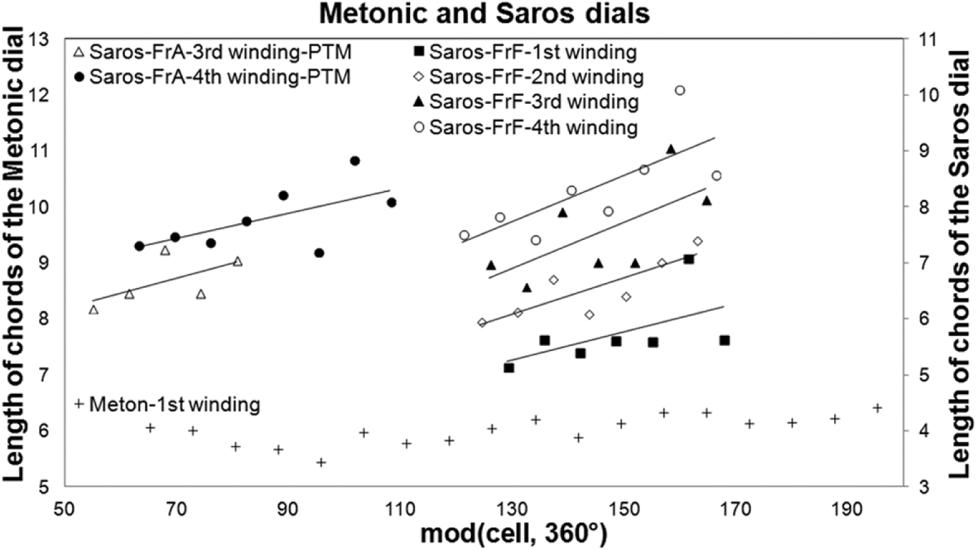
Plot of the measurements of the chords of the cells of the first winding for the Metonic spiral and of several windings for the Saros spiral.
5. Conclusions
The back face of the Antikythera Mechanism consisted of two main spiral dials. The pointer of the Metonic dial is the only pointer of a spiral on the Antikythera Mechanism that has survived. A careful examination at the point where it was attached to its axis reveals the structure of its pivot, a very clever mechanism that transferred the motion of the axis to the pointer allowing it at the same time to freely move so as to follow the gap between the windings of the spiral. Furthermore, the structure of the pivot of the pointer is quite extensively described on the back cover inscriptions of the Mechanism, confirming our reconstruction.
The analysis of the type of the spirals confirms Wright’s first report 25 that the spirals are Half Circles Spirals. The results show that both the Metonic and the Saros dial of the back face of the Antikythera Mechanism were designed as Half Circles Spirals, drawn from two different centres. The two centres of the Metonic dial are the pointer centre and an upper centre while the two centres of the Saros dial are the pointer centre and a lower centre.
The difference between the placement of the two centres in the two spirals may seem at first as a peculiarity in the way the mechanic worked, as one would expect the extra centres to be either both upper or both lower centres. This difference however is due to the different structure of the two spirals. The mechanic worked in the same way in both spirals, e.g. beginning from the extra centre in order to draw the first semicircle of each spiral (the left one for the Metonic dial, the right one for the Saros dial) and moving on to the pointer centre (this being also the visible one when the Mechanism was constructed) in order to draw the opposite semicircle. He could have of course worked the other way around, beginning from the last semicircle.
The eccentricity that would be produced, by the half-circle spiral construction, to the readings of the semicircles that were not drawn from the pointer centre was skilfully avoided as these cell divisions are proven to have been drawn so that they all point to the pointer centre. The increasing length of chords seems to be a technique, well known to the constructor of the Antikythera Mechanism. Besides the Saros spiral (§4.3) a similar construction with increasing chord lengths has been proposed for the front zodiac dial by Evans et al. 26 In the case of the zodiac dial it is proposed for producing a desired eccentricity, while, for the back dials, it was done for avoiding an unwanted eccentricity. The mechanic’s way of thinking and working is ingenious.
Footnotes
Acknowledgements
The authors acknowledge the cooperation of the Antikythera Mechanism Research Project and the National Archaeological Museum in Athens. In particular they would like to thank Mary Zafeiropoulou for the use of fragments E and F and Professor D. Papadopoulos for assistance in formulating ![]() . All CT slices are copyright of the Antikythera Mechanism Research Project. We would also like to thank an anonymous referee for improving the clarity of this article. M. Anastasiou would like to express her gratitude to the Aristotle University for a Ph.D. scholarship and to A. Anastasiou for his assistance in designing the reconstruction of the pointer mechanism.
. All CT slices are copyright of the Antikythera Mechanism Research Project. We would also like to thank an anonymous referee for improving the clarity of this article. M. Anastasiou would like to express her gratitude to the Aristotle University for a Ph.D. scholarship and to A. Anastasiou for his assistance in designing the reconstruction of the pointer mechanism.
Notes on Contributors
Anastasiou Magdalini (
John H. Seiradakis (
Christián C. Carman (
Kyriakos Efstathiou (
References
Supplementary Material
Please find the following supplemental material available below.
For Open Access articles published under a Creative Commons License, all supplemental material carries the same license as the article it is associated with.
For non-Open Access articles published, all supplemental material carries a non-exclusive license, and permission requests for re-use of supplemental material or any part of supplemental material shall be sent directly to the copyright owner as specified in the copyright notice associated with the article.