
Abstract
Open microcellular polylactic acid foams with a fibrous polytetrafluoroethylene additive were prepared by a coreback foam injection molding technique. The effects of this fibrous additive on the foam cell structure were investigated. Fibrous polytetrafluoroethylene forms a network structure in polylactic acid in metering and mixing processes. The fibrous polytetrafluoroethylene network increased the viscoelasticity of polylactic acid and provided polylactic acid with a strain-hardening property. The network also provided heterogeneous bubble nucleation sites for physical foaming. However, because of the slow crystallization rate of polylactic acid, the fibrous polytetrafluoroethylene additive did not promote the nucleation of polylactic acid crystals under fast cooling conditions. During fast cooling, such as injection molding cooling conditions, the crystals induced by the fibrous polytetrafluoroethylene network could not behave as bubble nucleation sites. Thus, changes in rheological properties and the increased number of heterogeneous sites contributed to the decrease in cell size, the increase in the number density of cells and the increase in the open cell content. As the number density of cells increased, the cell walls with the fibrous polytetrafluoroethylene fibrous additive became so thin that they could be easily fibrillated by a stretching operation during the coreback operation, while their strain-hardening property prevented the walls from complete breakage. Synergistically conducting cell reduction and stretching (coreback) operations, high expansion ratio foams with high open cell content were prepared. When we adjusted the foaming temperature and holding time, five-fold expansion (i.e. 80% void ratio) foams with cell diameters less than 25 µm and open cell contents (OCC) higher than 80% were produced.
Keywords
Introduction
Currently, polylactic acid (PLA) is the most well-known bio-based polymer because of its high compostability and biocompatibility.1–5 PLA has been used as a substitute for petroleum-based plastics in various applications, such as food trays, packaging, and medical parts. In tissue engineering, porous PLA has been studied for use as a polymer scaffold because of its biocompatibility.6–8 One way to prepare porous PLA is physical foaming. However, PLA is known as a difficult polymer to foam because of its slow crystallization rate and low melt tension. In a review, Nofar and Park 4 summarized several attempts to improve the foamability of the PLA family. For example, PLA’s degree of crystallinity and mechanical, rheological, and gas barrier properties have been controlled by manipulating the ratio of L- and D-lactic acid stereoisomers. 9 The melting properties of PLA have also been modified by several methods, such as adding a branching chain structure with a chain extender,10–12 changing the molecular weight 13 and adding nanoclay.14–16 Several processing techniques, such as batch foaming,11,13,17 extrusion foaming,12,18,19 bead foaming,4,20 and foam injection molding21–23 have also been tested to foam PLA. Among these techniques, structural foam injection molding has been intensively studied to control cell nucleation and coalescence and to create a microcellular foam. However, the porosity (void fraction) or expansion ratio of the obtained foams was not very high until the coreback operation (precise mold opening) technique was combined. The reported porosity of structural foaming without the coreback operation was approximately 5–15%. 23 To increase the porosity of the foams, structural foam injection molding was combined with the coreback operation.14,15 When the coreback operation is combined with microcellular foaming, the expansion ratio can be increased. Ameli et al. 15 prepared a nanocomposite PLA foam with a porosity of 65% and a minimum average cell size of 38 µm using a high-pressure foam injection molding with a coreback operation. Ameli et al. also adopted a short-shot foam molding technique to produce the foam-injected samples, and they achieved a fine cell PLA foam with an average cell size of 20 µm and a porosity of 30%. To the best of our knowledge, no foaming techniques have yet produced PLA foams with porosity greater than 65% and open cell content (OCC) greater than 60%.
In this study, employing a coreback foam injection molding technique and improving the foamability of PLA with a polytetrafluoroethylene (PTFE) additive, open cellular PLA foams with both porosity and OCC above 80% were prepared. The PTFE additive forms a fibrous network structure in the polymer during the melt blending process, 24 resulting in the so-called in situ micro-fibrillary composites (MFCs).25–27 Rizvi et al. 25 used a commercially available PTFE as an MFC for polypropylene extrusion foaming and demonstrated its excellent performance in reducing cell size. The fibrous network can also be formed in PLA by melt blending during the injection molding process. The presence of the network structure provides PLA with a strain-hardening property and an increase in elongational viscosity. 28 The strain-hardening property makes large stretching deformations possible, and the higher elongational viscosity makes cell size reduction possible. Furthermore, this property increases the specific surface area and increases the heterogeneous bubble nucleation sites for physical foaming. 25
The coreback operation technique, i.e. the mold opening technique, can decouple the foaming process from the injection process and thus enable high porosity with uniform cell morphology. 29 In addition to those advantages for physical foaming, the coreback technique can add a large degree of stretching deformation to cell walls during foaming and can induce cell opening phenomena during high expansion ratio foaming. As the number density of cells increases and the cell size decreases, the cell walls become so thin that they can be easily fibrillated by higher stretching deformation. Synergistically conducting cell reduction and stretching operations in the coreback foam injection molding process, high expansion ratio foams with high OCC could be prepared.
Experimental
Materials
The base polymer used in this study was polylactic acid (PLA, TP-4000, UNITIKA Ltd, Japan), which is equivalent to a 4032D grade polymer (Nature Works, LLC, USA). The melt flow rate of the PLA was 3 g/10 min, and the D-isomer concentration was 1.5%. The in situ MFCs used in this study were acrylic-modified PTFE (Metablen A3000, Mitsubishi Chemical Co., Ltd, Japan), which is commercially available. Before conducting the injection molding, the PTFE was blended with the base PLA at 1.5 wt.% and 3.0 wt.% concentrations. All materials were used as received. N2 gas (Izumi Sangyo Co., Ltd, Japan, 99.7% purity) was used as a physical blowing agent.
Experimental setup
A 35-tonnage injection molding machine (JSW J35ELIII-F, MuCell®, Japan Steel Work Ltd, Japan) and a supercritical fluid (SCF) delivery system (SCF system SII TRJ-10-A-MPD, Trexel, Inc.) were used. Figure 1 shows a schematic diagram of the injection molding machine and SCF delivery system. N2 was pressurized to 24–27 MPa by the SCF delivery system, delivered into the molten polymer in the barrel of the injection machine through an injector valve and dissolved into the molten polymer under a high shear rate and pressure. The concentration of N2 in the molten polymer was adjusted by manipulating the injector valve’s open period. The polymer containing N2 was injected into a mold cavity for foaming. The mold had a box-type cavity with a 1.5 mm diameter gate. The cavity geometry is shown in Figure 2. The cavity size was 50 mm in width, 70 mm in length, and 2 mm in initial thickness, which could be expanded in the thickness direction to 10 mm. A data logging system (Mold Marshaling system EPD-001S, Futaba Corp., Japan) was mounted on the mold to monitor the pressure and temperature of the injected polymer in the cavity; this system acquired data every 20 ms. Two ejector-pin-type pressure sensors (EPSEJL-04.0, Futaba Corp., Japan) and two infrared temperature sensors (EPSSZL-04.0, Futaba Corp.) installed at the mold cavity location are shown in Figure 2.
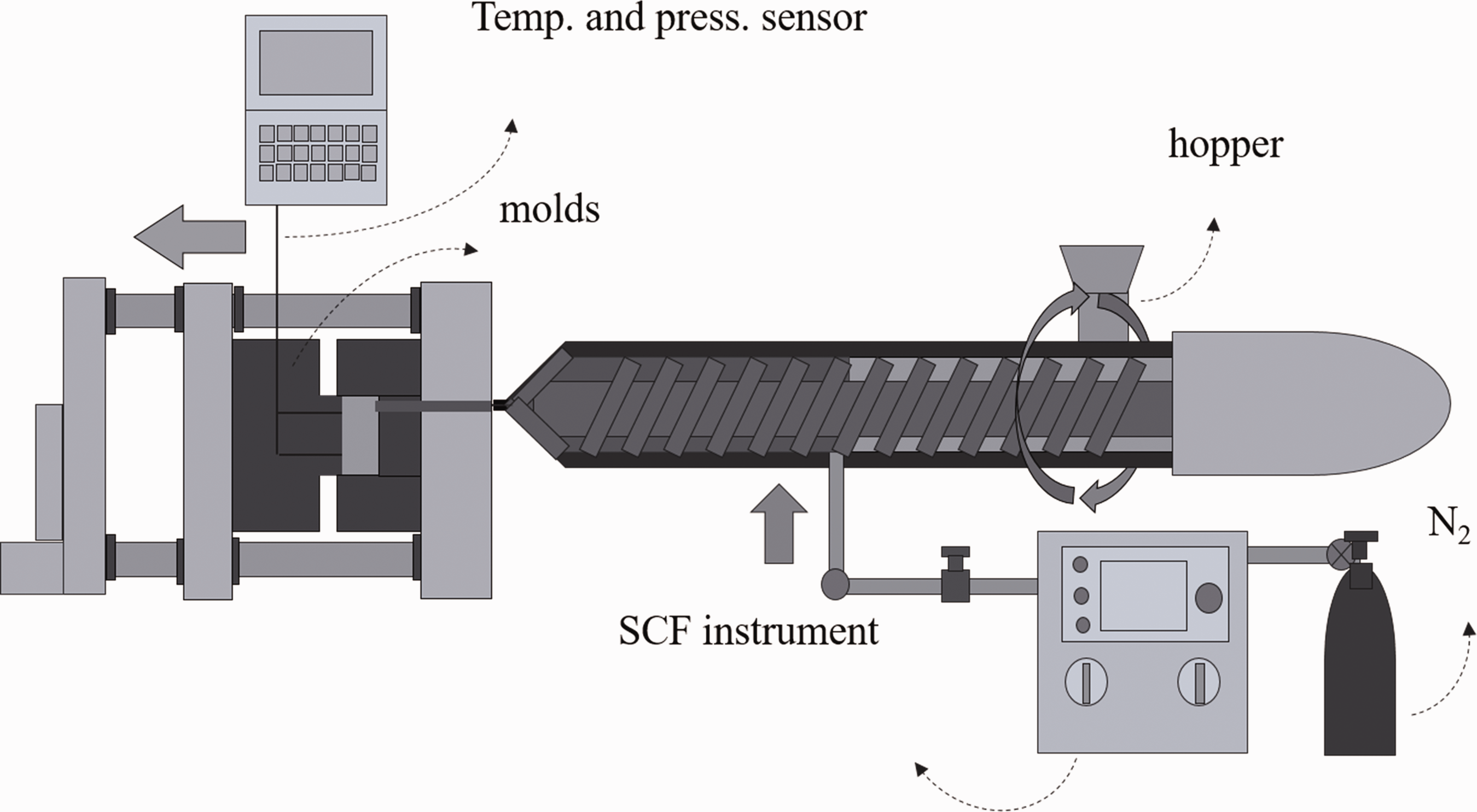
Schematic of the foam injection molding machine.
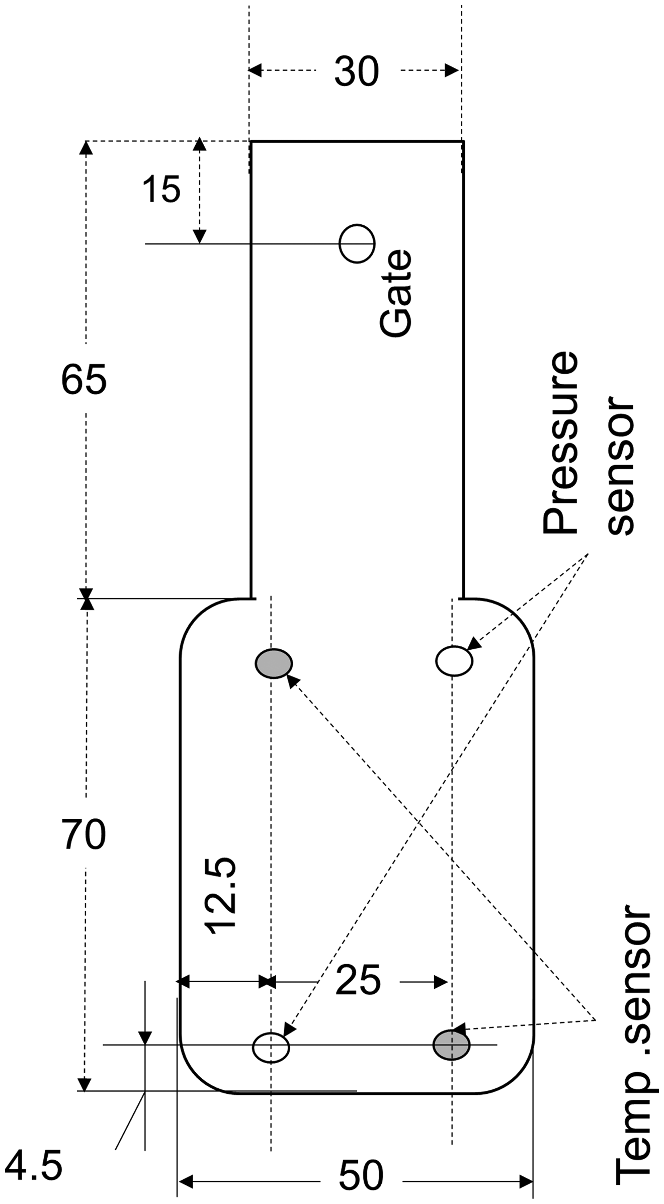
Schematic of the mold.
The coreback operation makes the structural injection molding process slightly differ from that of the conventional foam injection molding process. The difference is observed at steps after the polymer is filled in the mold. After the mold is filled with the polymer, dwelling (holding) pressure is exerted. At the end of the dwelling time, a portion of the mold is moved to quickly increase the mold cavity volume, which rapidly reduces the cavity pressure. Figure 3 shows an example of the pressure and temperature profiles of polymer in the mold cavity, which were monitored in real time by the data logging system. As shown in Figure 3, both the temperature and pressure gradually decreased after the completion of injection. The pressure dropped suddenly when the coreback operation commenced. The sudden pressure reduction induced the polymer to foam. The temperature at the time of pressure reduction was considered the foaming temperature, which is calculated by averaging the measurements of the two temperature sensors. The foaming temperature and the polymer viscosity at the time of foaming could be tuned by changing the dwelling (pressure holding) time, which is the period between the completion of injection and the initiation of the coreback operation, as indicated in Figure 3.
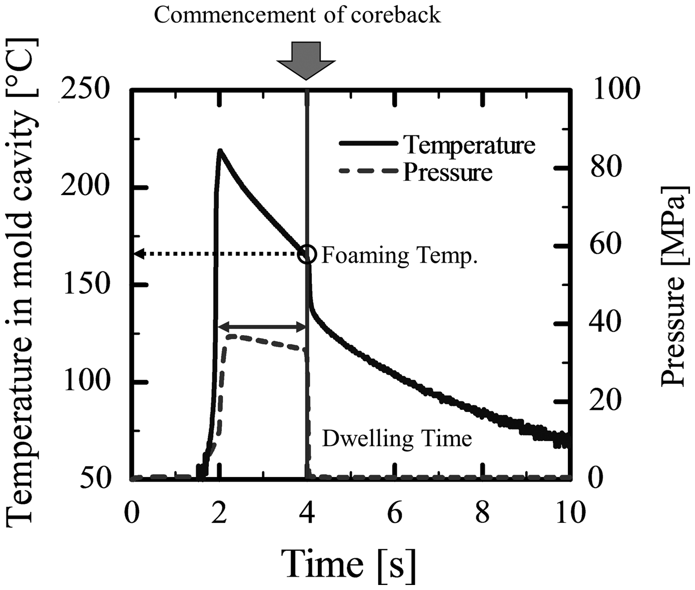
Temperature and pressure profiles in the mold cavity.
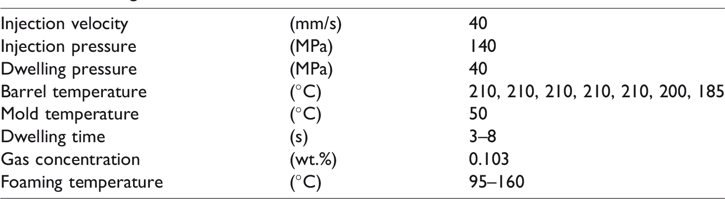
Table 1 shows the coreback foam injection molding process operating conditions. PLA foams were prepared with different weight percentages of PTFE and varying expansion ratios.
Molding conditions of PLA and PLA/PTFE foam.
Characterization of cell morphology
The expansion ratio, Eratio, of foam is calculated by equation (1)
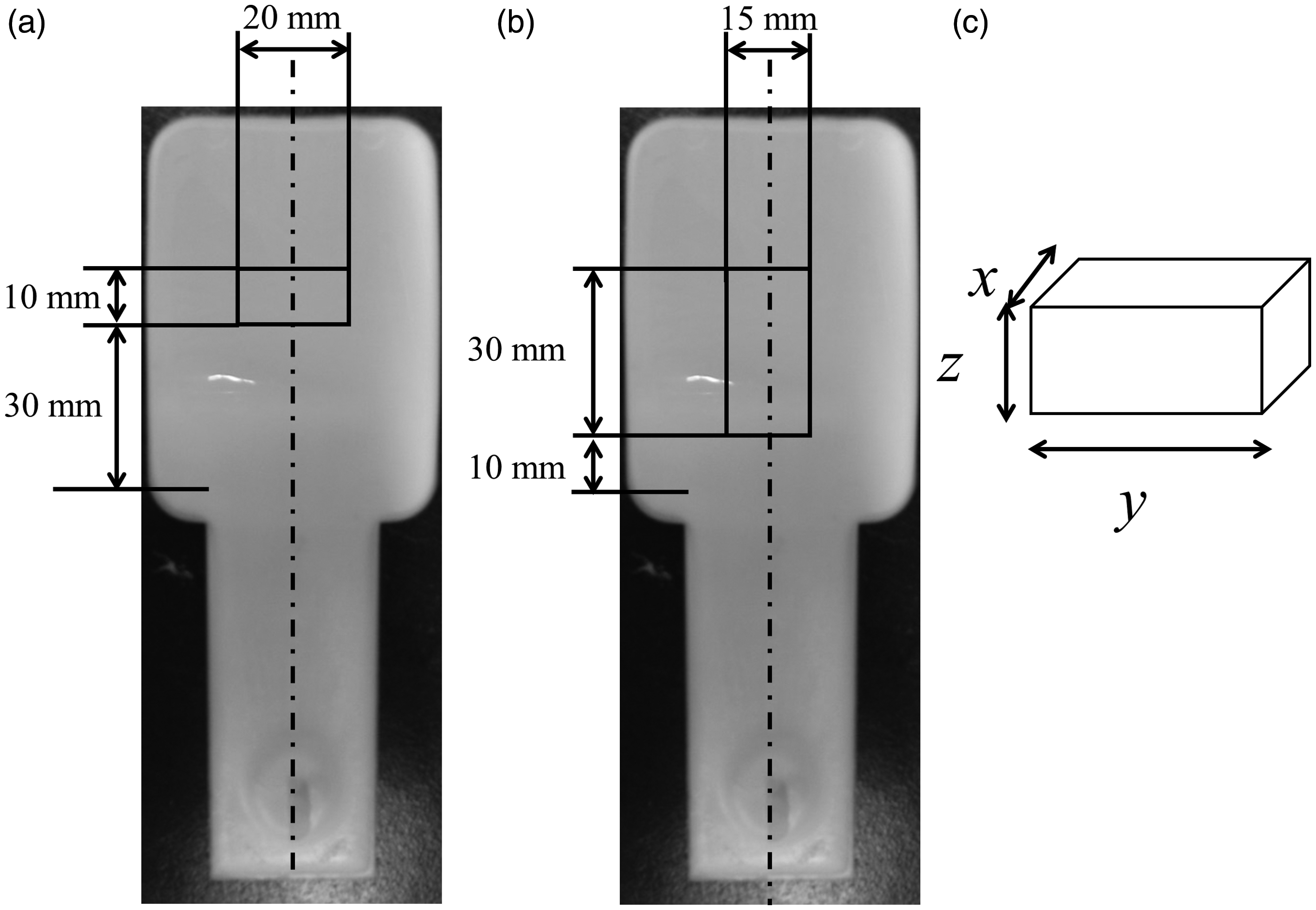
Digital camera images of the foamed samples and the location cut out for the (a) SEM specimen, (b) pycnometer specimen, and (c) schematics of the pycnometer sample.
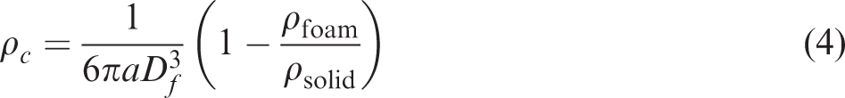
The foams were prepared by moving a mold part from 2 mm to a designated distance in the coreback direction. Therefore, the cells tended to be elongated in the coreback direction with elliptic foams at lower expansion ratios and fibrous foams at higher expansion ratios. In contrast, the cell shapes observed from the perpendicular view tended to be spherical foams at lower expansion ratios. When the cell shape can be regarded as spherical, the average cell diameter, Df, and the number density of cells, ρc, were calculated from the SEM images using equations (2) and (3)
30
However, the cells are elongated in the coreback direction, and the cell shapes change to elliptic and fibrous as the coreback distance is increased. The degree of elongation in the coreback distance was calculated by measuring the aspect ratio of cells from the SEM images. The aspect ratio was defined by the ratio of cell size, Df, to the average length, L, of each cell as measured from the SEM images taken in the direction parallel to the coreback direction. Then, when the shape of the cells is elliptical, the number density of the cells is modified with the aspect ratio of the cell, a, by equation (4)
29
Measurement of OCC
The apparent density of foam, ρfoam, was measured by cutting a 30 × 15 mm specimen from the foamed injection molded samples as shown in Figure 4(b) and (c). A pycnometer (AccuPyc2000, Shimadzu Corp., Japan) with N2 was used for the measurement. The OCC (volume fraction of open cellular) was then calculated from the density using equation (5)

Measurement of rheological properties
The rheological properties of PLA and PLA/PTFE composites were measured by rheometer (ARES, TA instruments Inc.). All rheological measurements were carried out after drying the sample for one day in an oven at 50°C.
For the elongational viscosity measurement, specimens of 10 × 18 × 0.8 mm in width, length, and thickness, respectively, were prepared using a hot press (Imoto Ltd, Japan) for 5 min at 40 MPa compression pressure at 200°C. The elongational viscosity was measured using the rheometer with an extensional viscosity fixture at 172°C and four different strain rates, i.e. 0.1, 0.2, 0.5, and 1.0 1/s.
For the viscoelasticity measurement, specimens 25 × 2 mm in diameter and thickness were cut out from the non-foamed injection molded sample. The storage and loss moduli and the complex viscosity were measured at 175°C at frequencies from 10 to 0.01 rad/s with 1% strain. The temperature dependency of those viscoelastic properties was also measured in a temperature range from 120 to 200°C by cooling the specimen at a rate of −2°C/min from 200°C. The same parallel plate device was used for the measurement with 1% strain at 0.63 rad/s.
Observation of crystallization behaviors of PLA and PLA/PTFE blends
Using a fast scanning chip calorimeter (Flash DSC1, Mettler Toledo International Inc.) and a conventional differential scanning calorimeter (DSC, Pyris 1, ParkinElmer Inc.), non-isothermal crystallization behaviors of PLA and PLA/PTFE composites were investigated at different cooling rates. The thermograms at the normal cooling rates of −5 and −10°C/min were obtained with the conventional DSC, and those at the rapid cooling rates of −5, −10, −15, −20, −120, −300, and −900°C/min were obtained with the flash DSC. To see the effect of the presence of PTFE on the PLA crystallization behavior, PLA/PTFE composites were prepared at three different weight percentages of PTFE (0, 1.5, and 3.0 wt.%) and measured by both types of DSC. All the measurements were conducted under N2 purge.
Observation of the fibrous structure of PTFE in PLA
To observe the presence of a PTFE fibrous network structure, PLA and PLA/PTFE foams were immersed in chloroform (purity 99%, Wako Pure Chemical Industries Ltd., Japan) for 6.5 h to leach PLA from the foams. The residuals were observed by SEM after drying.
Visual observation of batch foaming of PLA/PTFE
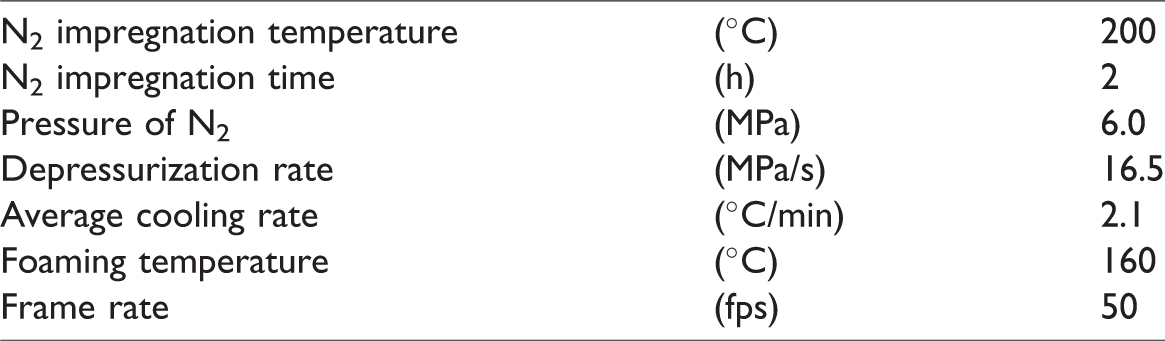
To confirm the effect of PTFE on foaming, visual observation experiments were conducted. The experimental apparatus details can be found elsewhere.31–33 For visual observation, a disc-shaped specimen with a 5 mm diameter and 0.5 mm thickness was prepared for each PLA and PLA/PTFE (3.0 wt.%) composite. The specimens were made from a non-foamed injection molded sample. The sample was cut into small pieces, and a piece was hot-pressed at 210°C under 40 MPa compression force for 5 min. After hot pressing, the specimen was quenched and dried for 1 day. A specimen was set into the view cell and N2 gas was dissolved into it by pressurizing the cell with N2 at 5.4 MPa and holding the temperature at 200°C for 2 h. Then, the specimen was cooled down at an average cooling rate of −3°C/min. When the temperature reached a designated level, the view cell was depressurized by releasing the N2 from the cell, and the specimen foamed. Table 2 shows the batch foaming conditions.
Batch foaming conditions of PLA and PLA/PTFE foam.
Results and discussion
Effects of PTFE on rheological and crystalline properties
Figure 5 shows the temperature dependence of the storage modulus and the absolute value of complex viscosity of both PLA and PLA/PTFE composites. With decreasing temperatures, the storage modulus and the complex viscosity increased. As the weight percentage of PTFE increased, the storage modulus increased. Both the absolute value of complex viscosity and the storage modulus of PLA alone rapidly increased at 115°C, while those of PLA/PTFE rapidly increased at 140°C. These rapid increments indicate the onset of crystallization of PLA. Thus, we demonstrated that adding PTFE to PLA promoted crystallization and shifted the crystallization temperature, Tc, to a higher temperature. Figure 6 shows the frequency dependence of storage and loss moduli measured at 175°C with 1% strain. In the low frequency region from 10−2 to 10−1, both moduli increased with the increase of the weight fraction of PTFE and leveled out at the low frequency region. These results demonstrated the presence of a network structure, which suppresses the strain relaxation and produces elasticity. Figure 7 shows SEM images of the surface of the PLA/PTFE foam after chloroform solution treatment. A network of PTFE fibers was observed.
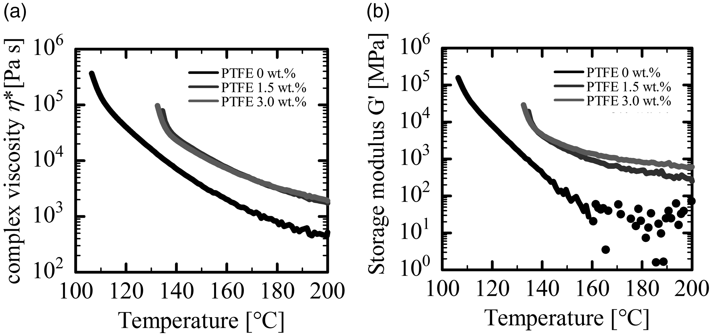
(a) Complex viscosity and (b) storage modulus of PLA/PTFE as a function of temperature.
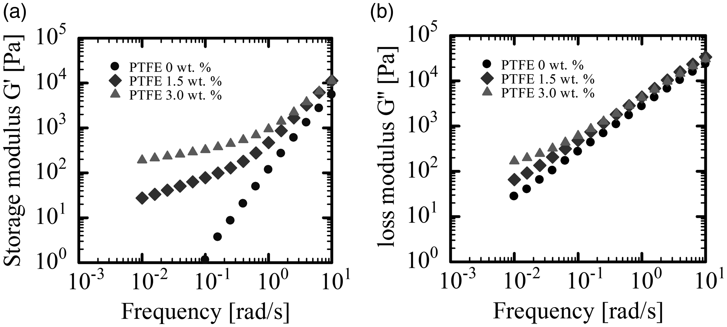
(a) Storage modulus and (b) loss modulus of PLA/PTFE as a function of frequency.
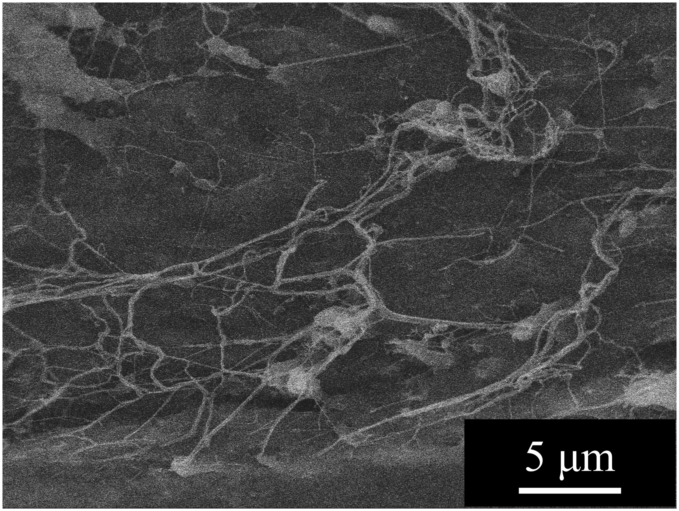
Network structure of PTFE in PLA foam.
Figure 8(a) shows DSC thermograms for non-isothermal cooling of PLA alone and PLA/PTFE (1.5 wt.% and 3.0 wt.%) composites, which were measured at a cooling rate of 5°C/min. There was no peak in the cooling curves of PLA alone. This result indicates that the crystallization of PLA alone is far slower than 5°C/min. In contrast, an exothermic crystallization peak was observed in the cooling curves of the PLA/PTFE composites. As seen, the crystallization enthalpy and crystallization temperature, Tc, increased with the PTFE content. These results showed that the PLA crystallization was enhanced by the presence of PTFE. It is conceivable that heterogeneous crystallization of PLA was enhanced by the presence of PTFE.
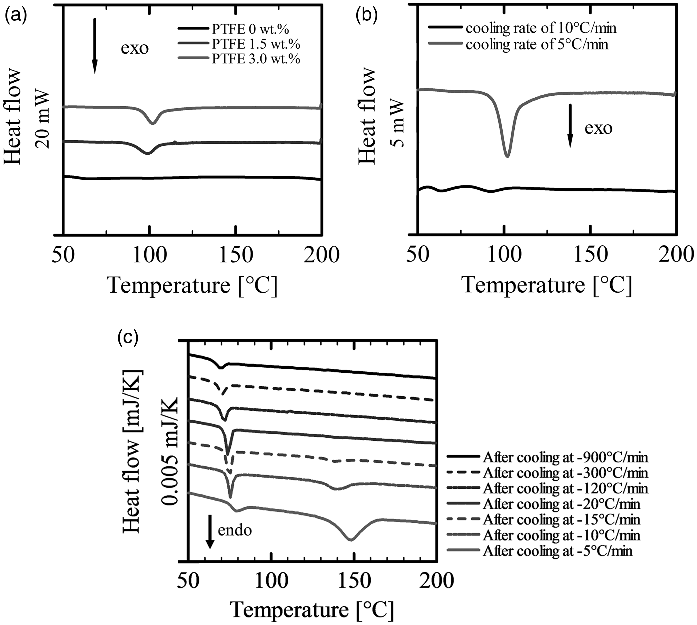
Non-isothermal DSC thermographs of PLA/PTFE (3.0 wt.%) at cooling rates of (a) 5°C/min, (b) 10°C/min, and (c) the second cycle after conducting the first cooling process at various cooling rates.
Figure 8(b) shows DSC thermograms for non-isothermal cooling of PLA/PTFE (3.0 wt.%) at a cooling rate of −10°C/min. The crystallization exothermic peak disappeared from the cooling curve measured at the rate of −10°C/min. Figure 8(c) shows flash DSC normalized thermograms by heating rates for non-isothermal heating of the PLA/PTFE blend with 3.0 wt.% PTFE. The heating curves were obtained in the second cycle after the cooling process of the first cycle conducted at different cooling rates from −5°C/min to −900°C/min. The endothermic melting peak completely disappeared when the cooling rate of the first cycle became faster than −20°C/min. These results indicate that PLA could not be crystallized at cooling rates faster than −20°C/min. The cooling rate of the polymer in the mold was approximately −14°C/s in our injection molding experiment, which is approximately two orders of magnitude faster than the cooling rate of the DSC measurements. It is plausible that the crystals themselves do not affect foaming, i.e. they do not play a role as heterogeneous cell nucleation sites in coreback foam injection molding.
Figure 9 shows the elongational viscosity of PLA alone and PLA/PTFE blends at two different PTFE contents, 1.5 and 3.0 wt.%. The measurements were conducted at 168°C for PLA alone and 172°C for PLA/PTFE composites. Plateau regions appeared in every elongational viscosity curve, which corresponds to infinitesimal deformation. 34 As seen in Figure 9, the elongational viscosity increased and the strain hardening behavior was enhanced by blending PTFE. Therefore, when the PLA/PTFE composites were used for foaming, the cell growth could be suppressed, and the operation window would be widened due to the emerging strain-hardening characteristic.
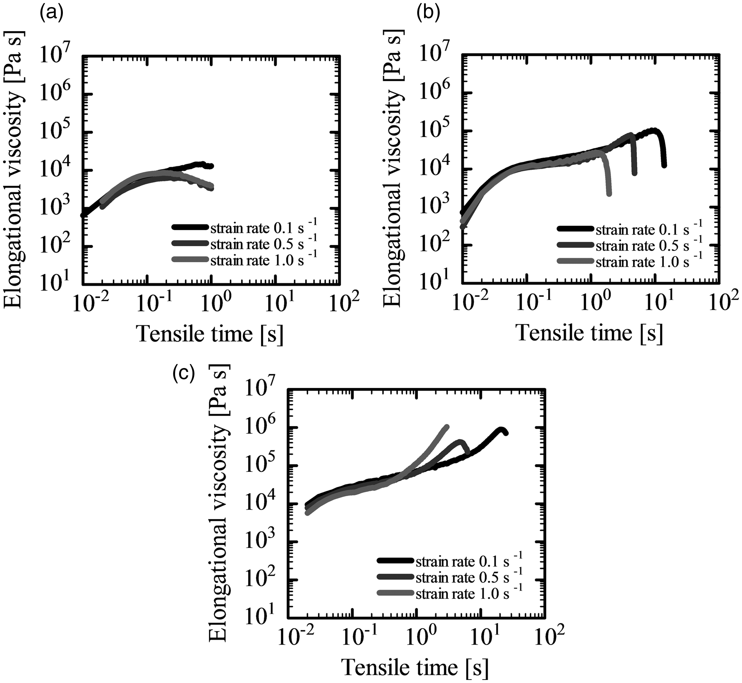
Elongational viscosity of (a) PLA alone, (b) with PTFE at weight fractions of 1.5 wt.%, and (c) 3.0 wt.%.
Effects of PTFE on cell structure
Figure 10 shows SEM images taken from the view perpendicular to the coreback direction of the PLA and PLA/PTFE foams with two-fold expansion ratios. To produce the two-fold expansion foams, the coreback operation commenced when the polymer temperature in the cavity was 105°C. It is clear that the cell size was reduced with the increase of PTFE weight fraction. The increase in complex viscosity could suppress the cell growth, and PTFE itself plays a role as a nucleation agent that increases the heterogeneous nucleation sites for physical foaming.
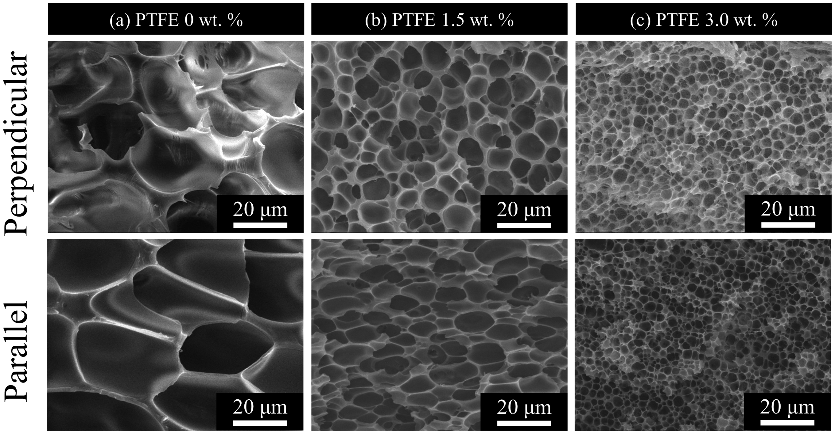
SEM images of cross-section of two-fold expansion rate PLA/PTFE foams with weight fractions of (a) 0 wt.%, (b) 1.5 wt.%, and (c) 3.0 wt.% at a foaming temperature of 100°C.
In our previous study of batch foaming of PLA with CO2, 17 it was shown that the growing crystals could provide active bubble nucleation sites and increase the number of bubbles. In the previous section, DSC analysis clarified that the presence of PTFE in PLA could enhance crystallization; however, in the fast cooling conditions of injection molding, the crystallization could not occur in PLA even in the presence of PTFE. To confirm that the increase in the number of bubbles and the decrease in cell size did not relate to the crystallization of PLA, visual observation experiments were conducted.
Figure 11 shows visual observation snapshots of the batch foaming behavior of PLA and PLA/PTFE. For visual observation, foaming was conducted at 130°C for PLA alone and 160°C for PLA/PTFE. As shown in Figure 5(a), the complex viscosity of PLA alone at 130°C is approximately the same as that of PLA/PTFE (3.0 wt.%) at 160°C. Comparing the snap shot of foaming of PLA alone with that of PLA/PTFE, the number of cells observed in the snap shot of PLA/PTFE batch foaming was larger than that observed for PLA alone. At 160°C, which is higher than Tc, the crystallization did not occur in PLA/PTFE. At 130°C, the crystallization did not occur in PLA alone. Thus, the increase in the number of cells (cells) in PLA/PTFE was not caused by the crystallization of PLA but rather by the presence of PTFE itself. In the foam injection molding process, crystallization did not occur at cooling rates faster than −20°C/min. As the DSC-based thermogram shown in Figure 8 and the visual observation of batch foaming experiments indicated, the increase in the number of cells was not caused by the crystallization or viscosity differences. PTFE granted a degree of heterogeneity that enhanced heterogeneous bubble nucleation.
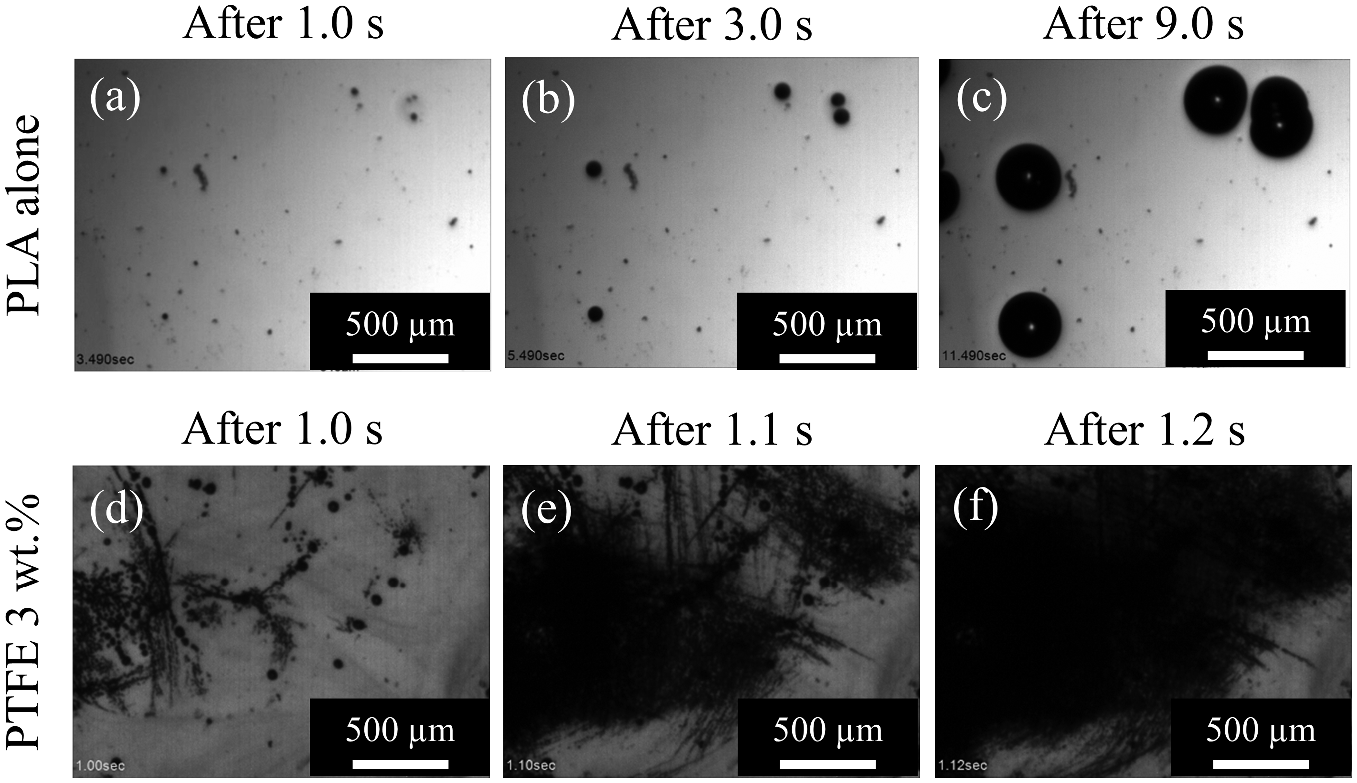
Foaming behavior of PLA sample with batch foaming process after (a) 1 s (b) 3 s, and (c) 9 s from decompression at foaming temperature of 130°C and PLA/PTFE (3.0 wt.%) sample with batch foaming process after (d) 1 s, (e) 1.1 s, and (f) 1.2 s from decompression at foaming temperature of 160°C.
Figure 12 shows the cell diameter and the number density of cells of two-fold expansion PLA foams as well as those of PLA/PTFE foams with varying PTFE contents. Foams were produced by the coreback foam injection molding process with different coreback timing to examine the effect of foaming temperature. With the increase in PTFE content, the cell diameter was reduced and the number density of cells was increased, especially in the temperature range of 90–110°C. For temperature dependency, the cell diameter was reduced, and the number of cells was increased as the foaming temperature was lowered. It is apparent in Figure 5 that the addition of PTFE as well as the reduction of foaming temperature increases the viscoelasticity, and the higher complex viscosity suppresses the polymer cell growth.
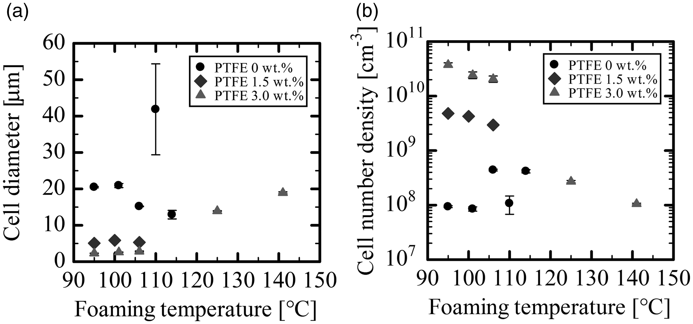
(a) Cell diameter and (b) cell number density of two-fold expansion PLA/PTFE foams as a function of foaming temperature.
The cell diameter of PLA and PLA/PTFE with 1.5% PTFE foams could not be measured in the temperature range from 125 to 140°C because cell wall rupture or coalescence occurred and because a large hollow structure was created in the foams. Even in the temperature range between 100 and 120°C, the cell morphology of PLA alone foams was unstable to some extent because the cell wall opening easily occurred given that the cell wall thinned as the cell size was reduced. In contrast, the PLA/PTFE (3.0 wt.%) foam showed a stable cell morphology even in the temperature range from 125 to 140°C and yielded a foam with cell size approximately 20 µm, slightly larger than those of foams prepared at temperatures lower than 120°C. These data clearly show that the operating temperature window of foaming was widened by fibrillated PTFE.
Figure 13(a) plots the OCC of two-fold expansion foams of PLA and PLA/PTFE with different contents against the foaming temperature. As the foaming temperature increased, the OCC of PLA alone and PLA/PTFE composites both increased, while it decreased in PLA/PTFE (3.0 wt.%) foam after reaching a maximum at a foaming temperature of approximately 110°C. The OCC of PLA alone and that of PLA/PTFE (1.5%) could not be measured at foaming temperatures higher than 110°C because of corrupted cells. For PLA/PTFE, cell corruption seemed to be suppressed by the presence of PTFE. Even though PTFE prevented cell corruption, the cell growth rate was increased, and the number density of cells decreased with the increase in foaming temperature. Then, because of the increase of cell size, the cell wall thickened, the cell wall opening was reduced, and OCC was reduced as the foaming temperature rose higher than 110°C.
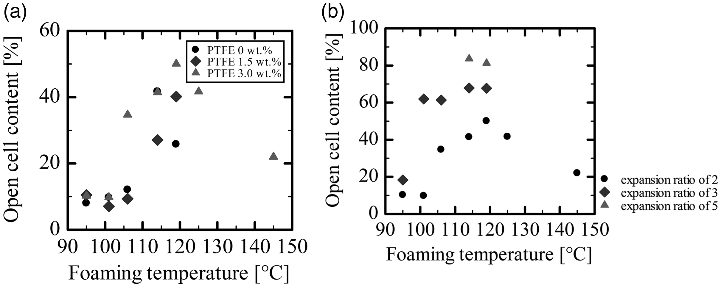
Open cell content of PLA alone and PLA/PTFE composite foam without skin layers: (a) two-fold expansion foams and (b) PLA/PTFE (3.0 wt.%) foams with different expansion ratios (2, 3, and 5).
At foaming temperatures below 110°C, the complex viscosity increased with the decrease of the foaming temperature. Even though the cell size decreased, and the cell wall became thinner, the OCC was reduced since the degree of deformation or stretching of the cell wall was not large enough to promote cell opening at lower foaming temperatures. Figure 13(b) shows the OCC of PLA/PTFE composite foams at three different expansion ratios (2, 3, and 5) prepared at various foaming temperatures. At a foaming temperature of approximately 110°C, the OCC increased as the expansion ratio increased. The maximum OCC that could be prepared was 80% in the five-fold expansion foam of PLA/PTFE without skin layers. OCC was closely related to cell wall thickness and the degree of cell wall deformation.
Figure 14 shows the cell morphology of PLA/PTFE (3.0 wt.%) at different expansion ratios. The images were taken from the view perpendicular to the coreback direction. The cell morphology became fibrillated as the expansion ratio increased. Without adding PTFE, the maximum expansion ratio that could be realized was three. The high elongational viscosity with the strain-hardening property fibrillated the cell morphology by preventing breakage and corruption of foams. A fibrillated open-cellular structure was produced by the large degree of stretching in the coreback operation.
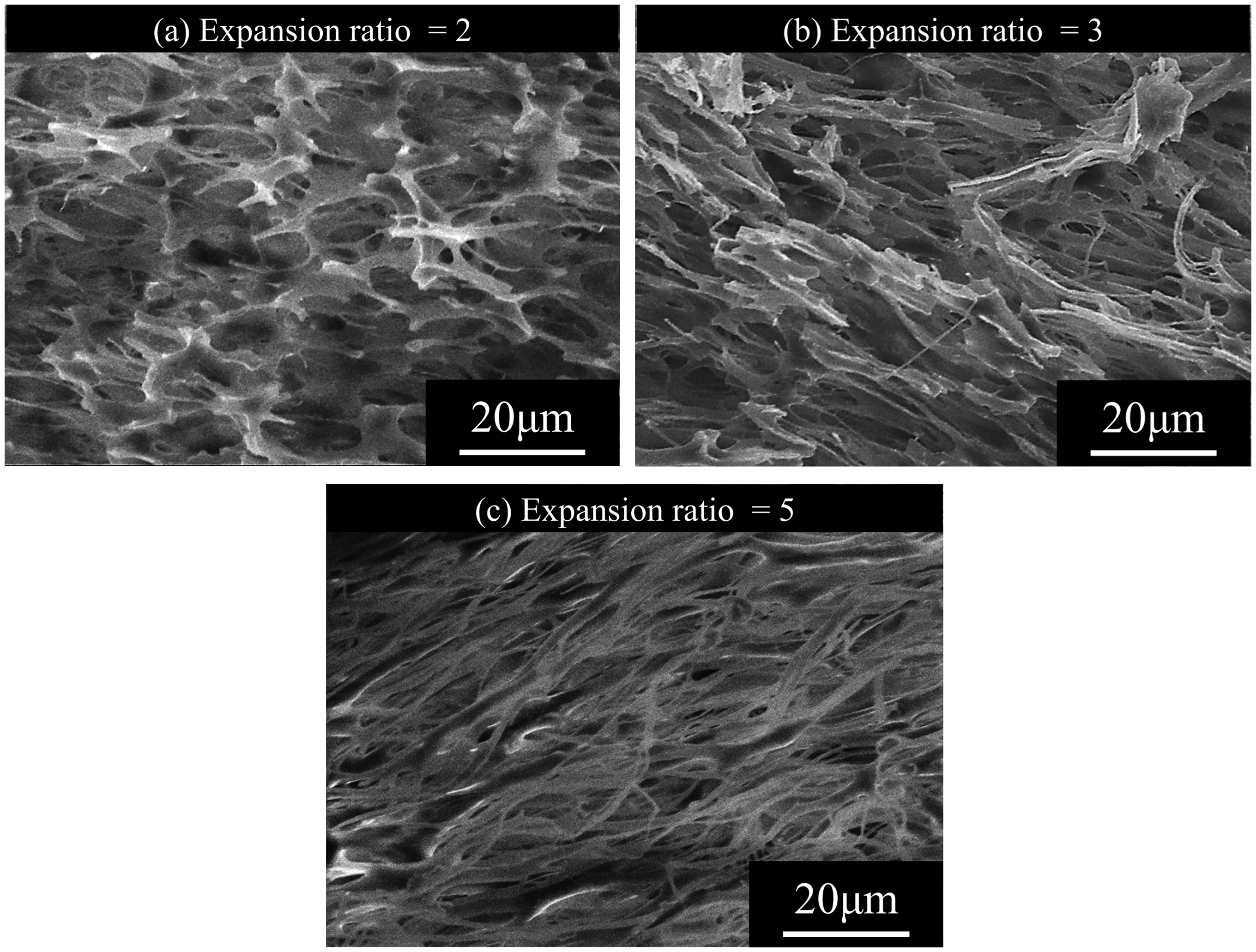
SEM images of parallel sections of (a) two-fold expansion, (b) three-fold expansion, and (c) five-fold expansion PLA/PTFE foam with a weight fraction of 3.0 wt.% at a foaming temperature of 110°C.
Conclusion
Fibrous PTFE was added to PLA to improve its foamability. PTFE forms a fibrous network structure in the polymer during the melt blending process. The complex viscosity increased and a strain-hardening property was produced with the addition of PTFE. PLA/PTFE foams were prepared by coreback foam injection molding. With the increase in PTFE content, the cell diameter was reduced, and the number density of cells was increased. The presence of PTFE in PLA enhanced the crystallization of PLA and shifted the crystallization temperature higher. However, in the rapid cooling process of injection molding, the rate of cooling was too rapid for PLA to crystallize. Even in the presence of PTFE, PLA could not be crystallized in the mold before coreback foaming. Thus, the heterogeneity that provides bubble nucleation sites came from PTFE itself, not from PLA crystals. The high elongational viscosity with strain-hardening property made higher expansion foams possible and could keep foams within the fibrillated structure by preventing cell structure disruptions. With the cell reduction and higher stretching, an OCC 80% was realized, and the operating temperature window was additionally widened by the addition of PTFE.
Footnotes
Declaration of Conflicting Interests
The author(s) declared no potential conflicts of interest with respect to the research, authorship, and/or publication of this article.
Funding
The author(s) received no financial support for the research, authorship, and/or publication of this article.