
Abstract
In recent years, triple periodic minimal surfaces (TPMS) have attracted attention in many applications such as biomaterials, aerospace, defense industry etc. lightweight components with high strength and functionally graded material (FGM). In particular, the mechanical properties and deformation behavior of these structures under load should be examined. In this study, it was aimed to evaluate the manufacturability and mechanical performance of fixed pore size and functional graded porosity (FGP) lattice structures produced by fused deposition modelling (FDM) method. TPMS primitive and gyroid lattice structures designed in the dimensions of 20 × 20 × 20 mm with fixed 20% pore size and functional graded (FG) from 20% to 40% pore size were used in the experiments. In order to reveal the effects of pore size on mechanical performance, uniaxial compression tests were carried out. In addition, for the validation of the experimental results, compression tests with the finite element method (FEM) were simulated for each sample. In the two different pore size changes tested in the study, the gyroid lattice structure showed the highest mechanical performance compared to the primitive lattice structure. In addition, the FEM results were in good agreement with the experimental results.
Keywords
Introduction
Lattice structures are periodic structures with repeating unit cells in three dimensions. 1 Especially lattice structures are used in different industrial areas due to their lightness, good energy absorption under load, good thermal conductivity and sound insulation.2–10 These structures are classified according to the shape and arrangement of the porosities. Basically, lattice structures are divided into two groups: stochastic structures that do not show a certain order and non-stochastic structures that periodically repeat each other in a certain order. 11 Lattice structures, which have an important place among porous structures, are also one of the non-stochastic structures. In contrast to the stochastic structures, non-stochastic structures manufacturing 3D printing technologies allow engineers to design and produce polymer structure having engineered lattice structures. 12 Triple periodic minimal surfaces (TPMS)-based lattice structures within non-stochastic lattice structures are of great interest. TPMS-based lattice structures defined by a certain equation provide superiority over other lattice structures with interferable cell repeats and volume fractions for different lattice structures. In addition, when compared to computer aided design (CAD)-based lattice structures classified in non-stochastic porous structures, it also reduces the stress concentration that occurs under load. 13
There are multiple factors for determining the mechanical properties of lattice structures. These are cell topology, 14 cell size, 15 strut diameter, 16 pore size, 17 relative densities of unit cells, 18 and deformation behavior under load. The change in pore size of unit cells also has a significant effect on mechanical properties. By varying the porosity per unit volume, functional graded (FG) porosity can be created in lattice structures. 19 In this way, it can be made more functional compared to uniform lattice structures in terms of mechanical properties.
In the literature, it is frequently used in experimental studies, especially because of because of easy, economic processing, extensive material customization, reliability, dimension stability with the FDM technique and the cheapness of polylactic acid (PLA) production material.20,21 In addition to experimental studies, finite element method (FEM) provides both time and cost benefits in the estimation of stresses that may occur in lattice structures. For this reason, studies using different unit cells, different pore sizes and different production methods in the literature on the determination of the mechanical properties of TPMS-based lattice structures draw attention. Kadkhodapour et al. (2014) 22 applied compression tests to primitive and diamond lattice structures with uniform 30% and 60% pore sizes produced by polyjet technique. Afshar et al. (2016) 23 produced TPMS-based primitive and diamond lattice structures using fused deposition medelling (FDM) technique for the production and mechanical characterization of pore sizes by functional grading. They stated that primitive lattice structures show stress dominant deformation behavior, while diamond lattice structures show bending dominant deformation behavior. Maskery et al. (2017) 2 investigated their mechanical performance by producing TPMS-based primitive, gyroid and diamond lattice structures with polymer additive manufacturing method. When the elastic modulus is compared, they found that the primitive lattice structure is lower, and the primitive lattice structure can absorb more energy due to the stress-dominant deformation behaviors. Yu et al. (2019) 24 produced TPMS-based primitive and gyroid lattice structures by grading both homogeneity and porosity with the additive manufacturing technique. The mechanical performances and energy absorption abilities of the fabricated lattice structures were investigated. As a result of the mechanical tests, they stated that while the stress fluctuations of the primitive lattice structures were evident, the stress fluctuations were not evident in the gyroid lattice structures. In addition, when their energy absorption capabilities were compared, they found that primitive lattice structures were more successful than gyroid structures. Palaniyappan et al. (2021) 25 investigated the effects of printing parameters on the production of TPMS-based gyroid lattice structure containing PLA material to achieve maximum compression strength. In the experiments, were used three different printing speeds (10 mm/sec, 20 mm/sec, 30 mm/sec and 40 mm/sec), layer height (0.10 mm, 0.15 mm, 0.20 mm and 0.25 mm) and nozzle temperature (190°C, 200°C, 210°C and 220°C). The specimen produced at a nominal printing speed of 20 mm/sec and a layer height of 0.10 mm obtained the highest compressive strength and lower buckling during the compression test. Higuera et al. (2021) 26 investigated the mechanical properties and energy absorption of TPMS-based gyroid lattice structures produced in different thermoplastics (acrylonitrile butadiene styrene, polylactic acid, thermoplastic polyurethane and polyamide) and design parameters (cell size and volume fraction). Experimental results showed that elastic geometric stiffness increased for higher volume fractions and smaller cells in PLA fabrication material. Kladovasilakis et al. (2021) 20 investigated the mechanical behavior of TPMS-based gyroid, daimond and primitive lattice structures. They produced lattice structures at 10%, 20% and 30% relative densities by FDM technique using PLA and tested them under quasi-static compression. In their results, they revealed that the mechanical properties of TPMS-based lattice structures deteriorate with the decrease of relative density. Saleh et al. (2022) 27 produced TPMS-based daimond, gyroid and primitive lattice structures from PLA and PLA + carbon fiber (CF) materials using FDM technique. Uniaxial compression test was performed to determine the effect of CF on the mechanical properties of the lattice structures. They found that all CF-based TPMS constructs showed a higher compression modulus. Peng et al. (2022) 28 proposed new TPMS-based honeycomb structures (gyroid-honeycomb and primitive-honeycomb) with adjustable mechanical responses. In the results, they found that primitive-honeycomb exhibited higher elastic modulus and plateau stress than gyroid-honeycomb at various relative densities.
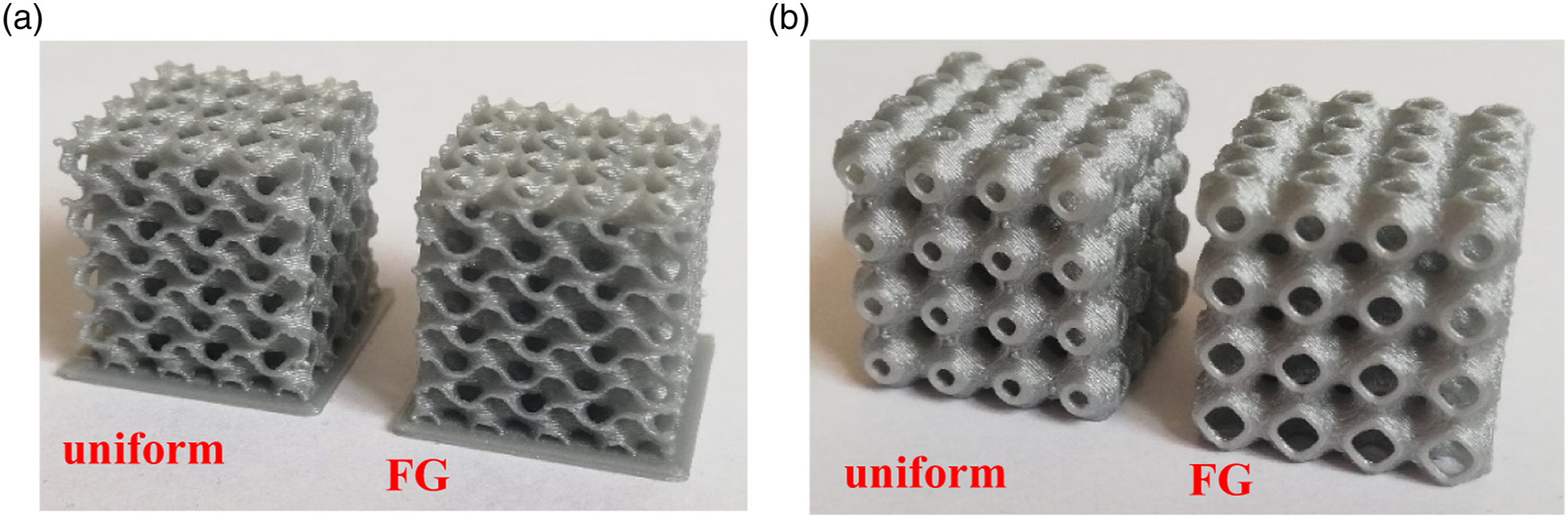
In this study, it was aimed to investigate the effects of pore sizes on mechanical properties of TPMS-based lattice structures, which are non-stochastic porous structures. In this context, TPMS-based primitive and gyroid lattice structures, which are uniform and functionally graded from 20% to 40% pore ratio, were produced using the FDM production method. The mechanical properties, deformation behavior and energy absorption capabilities of the lattice structures under the quasi-static loading are discussed. In addition, the results obtained by FEM analysis were compared with the experimental study. In the results obtained, the superiority of the FG lattice structures over the uniform lattice structures in mechanical properties was clearly revealed. The results obtained were given in detail in the sub-sections.
Experimental procedure
Design and fabricated of lattice structure
Primitive and gyroid lattice structures were used in the study to determine the mechanical properties of TPMS-based lattice structures. The lattice structures were created with the help of the level set equations given in equations (1) and (2) defined in the literature.
29
Lattice unit cells: (a) gyroid, (b) primitive. Lattice structures: (a) gyroid, (b) primitive.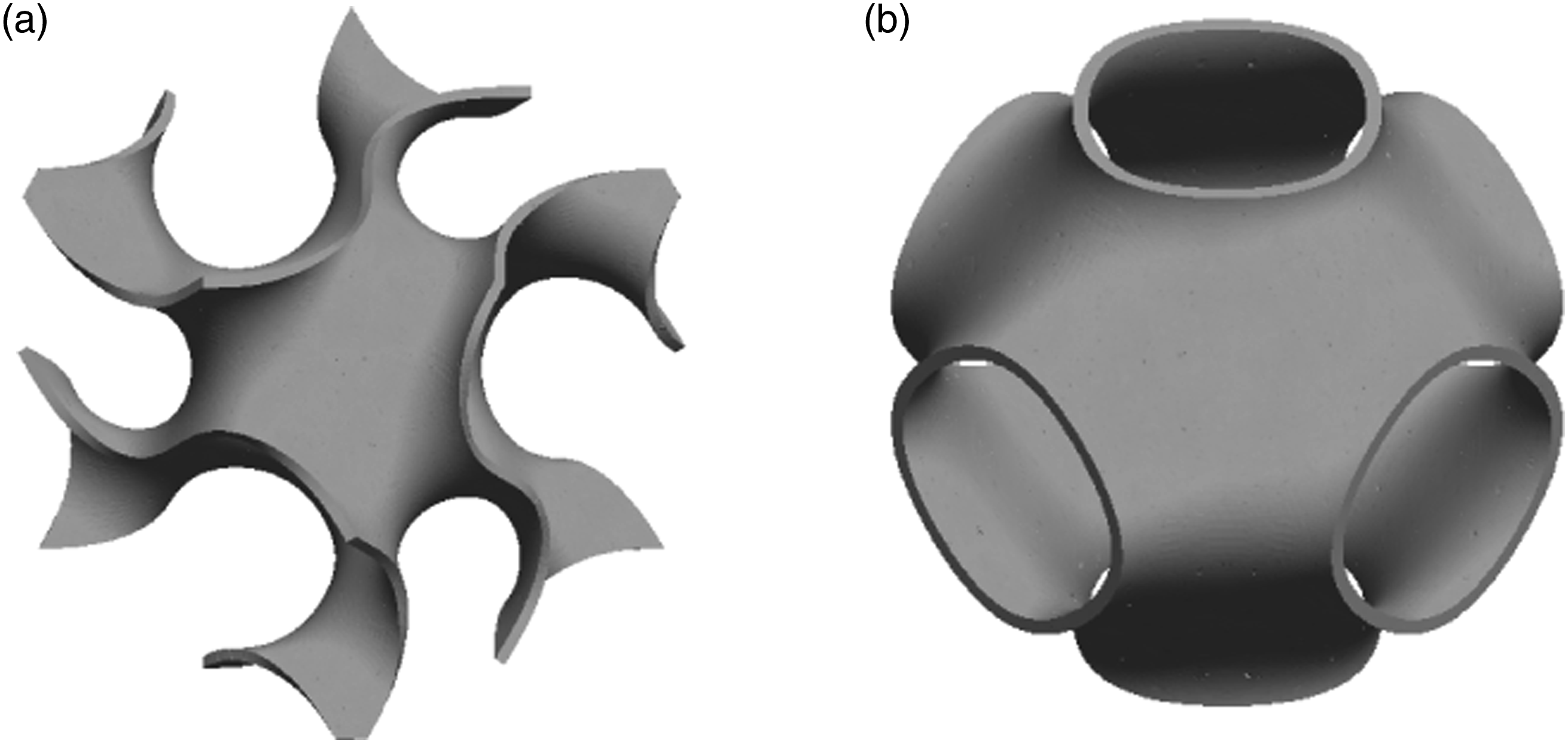


Compression test
In order to determine the mechanical properties of the lattice structures, quasi-static compression tests were carried out on the MTS brand test device (Figure 3). At the beginning of the test, the final strain value for all test specimens was 0.6 or terminated when the loading force exceeded the limit, and the constant loading rate was determined as 1 mm/min. The pressure was provided by the movement of the pore size of the moving head in the FG direction (−y). As a result of the experiments, stress-strain values were obtained for each lattice structure. In addition, the camera was recorded throughout the test in order to interpret the deformations that occurred. In the experiments, two pieces of each lattice structure (gyroid and primitive) were produced and mechanical tests were performed twice. According to the results obtained, the developed lattice structures showed similar results. Thus, the accuracy and precision of the lattice structures were confirmed. Compression test procedure.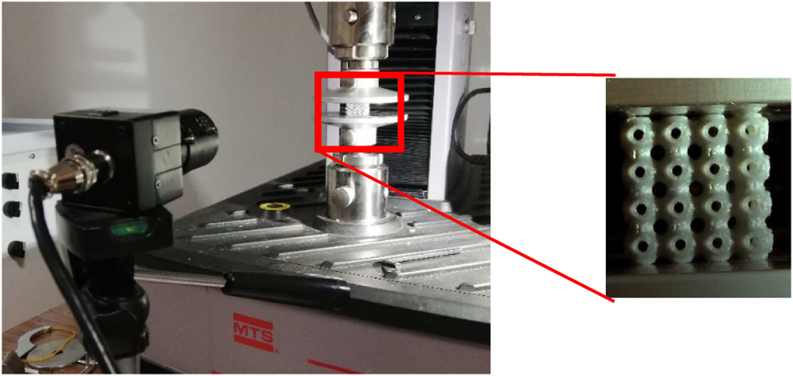
Finite element analaysis method
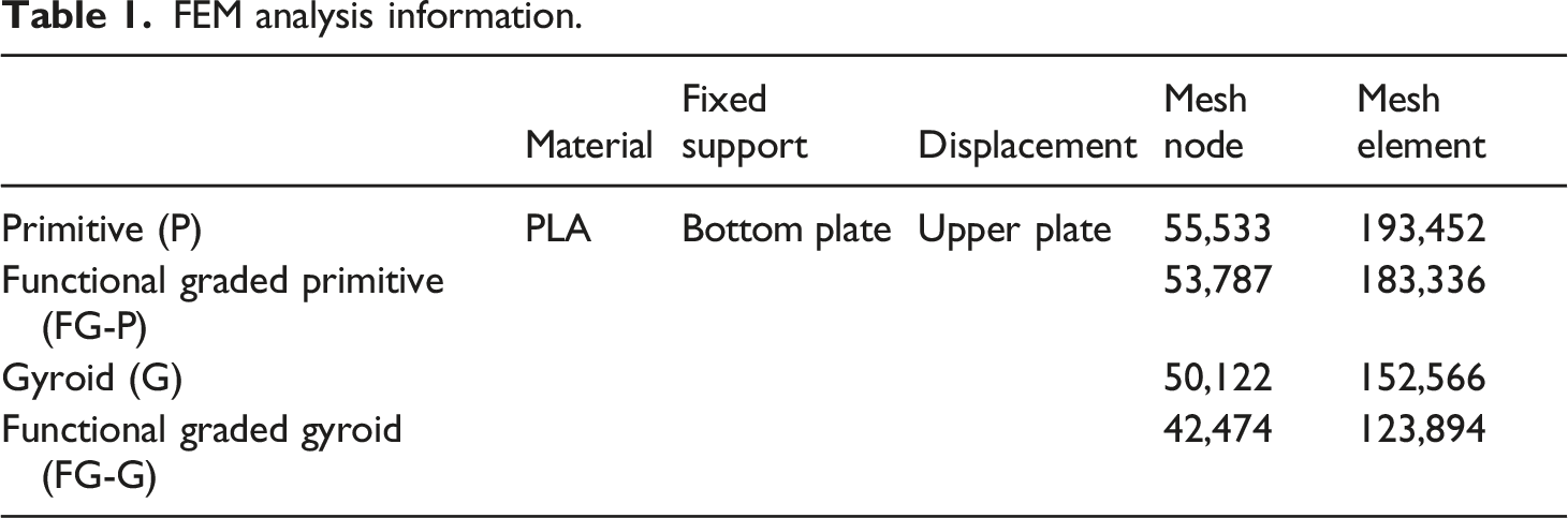
In order to interpret the compression response and energy absorbing capabilities of TPMS-based gyroid and primitive lattice structures with uniform pore size and functionally graded pore size, analysis were performed in the ANSYS/Explicit Dynamics interface. Rigid plates are modeled as top and bottom as shown in Figure 4. For uniaxial compression tests, the bottom plate was fixed while the top plate was moved in −y direction. In addition, a friction coefficient of 0.2 was defined between the plates and the lattice structure. For PLA material, it was modeled using an elastoplastic structural model with the von-Mises isotropic yield criterion. Mechanical properties were defined as density 1.24 g/cm3, Poisson ratio 0.36 and Young’s modulus 3500 MPa. Analysis information are given Table 1. Compression test FEM procedure. FEM analysis information.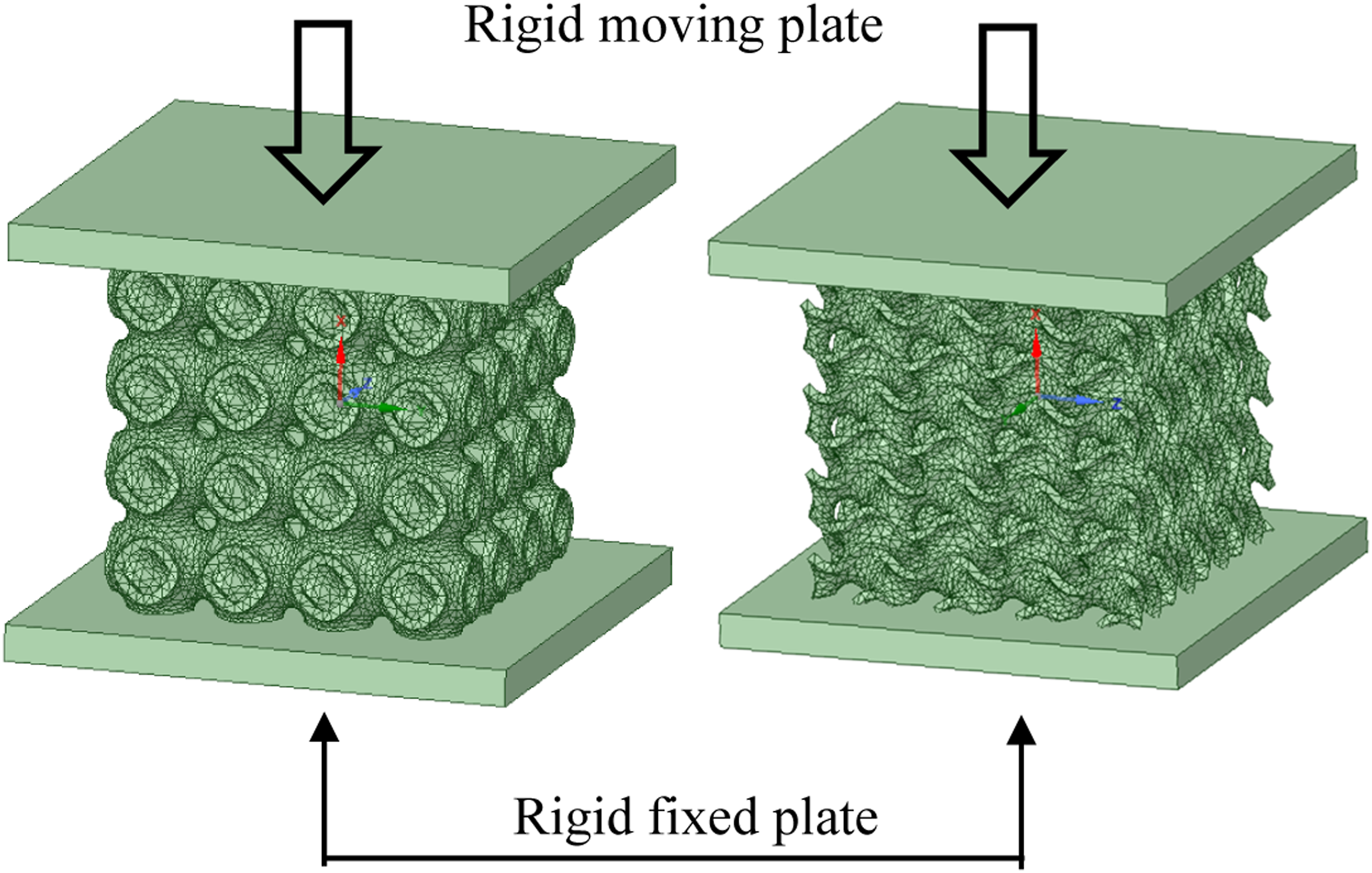
Results and discussion
Deformation behavior
Figure 5 shows the camera images taken during the compression tests of the uniform and FG primitive and gyroid lattice structures. At the initial strain (0%), all lattice structures are seen to be undamaged. In the obtained images, failure occurred in the uniform primitive lattice structures at an average of 0.05 strain (Figure 5(a)). Then, at 0.1 strain (10%), the unit cells in which breakage in the lattice structure began to collapse. The deformation behavior of primitive lattice structures is similar to conventional lattice or honeycomb structures. This is mostly because they all have distinct hollow layers.
24
With the increase of stress concentration in the lattice structure, the uniform primitive lattice structure collapsed significantly at approximately 0.3 (%30) strain. As a matter of fact, similar results have been reported in their studies on the mechanical deformations of primitive lattice structures in the literature.24,30 At 0.5 strain (50%), the lattice structure is fully deformed and concentrated. In the FG primitive lattice structure, the first deformation occurred in the lowest layer with the largest pore size (0.1 strain) (Figure 5(b)). This is due to the fact that the unit cells start from the region with the lowest wall thickness under load. Then, the deformation spread towards the direction where the pore size decreased in the form of collapse of the adding layer. At 0.5 strain (50%), the lattice structure is completely deformed. Experimental images obtained at different strain values; (a) uniform primitive, (b) FG primitive, (c) uniform gyroid, (d) FG gyroid.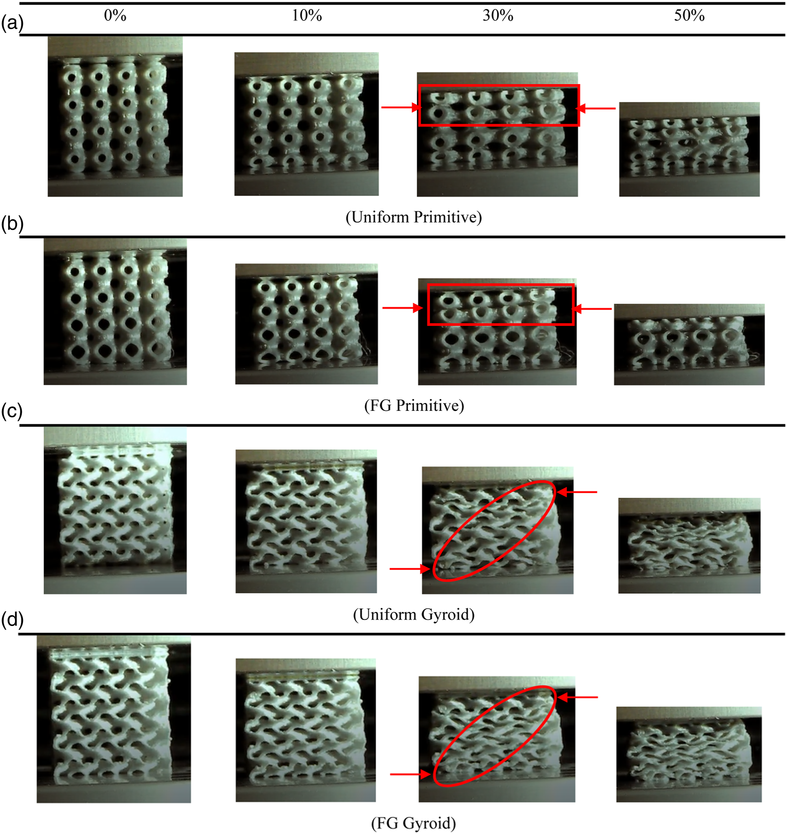
Gyroid structures deformation behavior is not as pronounced as primitive structures. Direct contact of interconnected cellular structures and inconspicuous hollow layers takes place. Thus, it buffers the deformation behavior and causes slip band and layer cracks that are not noticeable during the compression period of the gyroid structures.24,31 It started to deformation very slightly in the diagonal direction at approximately 0.1(%10) strain in the uniform gyroid lattice structure (Figure 5(c)). Shear band deformation behavior became increasingly evident when the strain value was about 0.3 (%30) strain. As a matter of fact, it has been reported in the literature that gyroid lattice structures deform in the form of a shear band under load.24,31 The direct contact of next gyroid unit cells with each other during deformation quickly filled the cracks in the lattice structure. The resulting shear band formation has disappeared. At a strain value of 0.5 (50%), the deformation of the lattice structure due to filled cracks occurred as a layer-by-layer collapse from shear band formation. In the FG gyroid structure, as in the FG primitive lattice structure, the deformation started from the unit cells with the largest pore size and spread to the unit cells with the lowest pore size (Figure 5(d)).
Mechanical performance
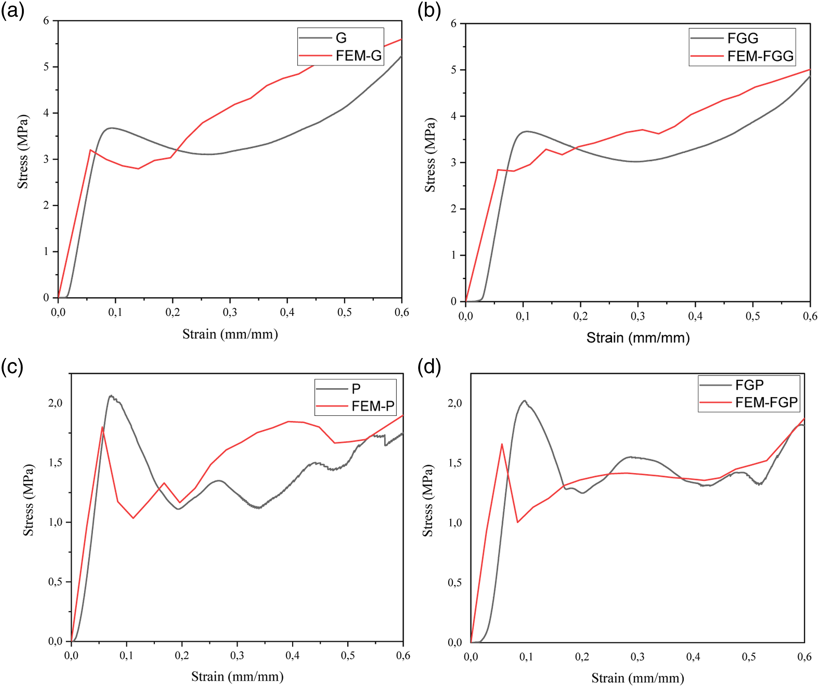
Figure 6 shows the stress-strain curves obtained from compression tests of uniform and FG primitive and gyroid lattice structures. Three phases occurred in all curves. These are the elastic stage, the plateau stage, and the densification stage. In the first stage, the stress-strain curve begins with a linear elastic region. With the slope of this region, the elastic modulus of the lattice structures is calculated. In the second stage, the highest stress value was observed just before the end of the elastic region. With the increase in stress, collapse occurs in the lattice structure. Plastic collapse occurred in the uniform primitive lattice structure at a strain value of 0.085, which corresponds to a stress of 2.11 MPa (Figure 6(a)). After this stage, the transition to the plateau region started with a sudden decrease in the stress value. In the plateau region, the behavior as a continuous increase and decrease in the stress value corresponding to the strain was observed. Especially in primitive lattice structures, deformed unit cells take longer to contact next unit cells than other lattice structures. Therefore, the difference between each peak and valley in the stress value is evident. In the last stage, all unit cells came into contact with each other and densification began at approximately 1.6 MPa stress and 0.56 strain, and the stress value showed a sudden increase. Stress-strain curve of %20 relative denstiy lattice; (a) primitive, (b) gyroid.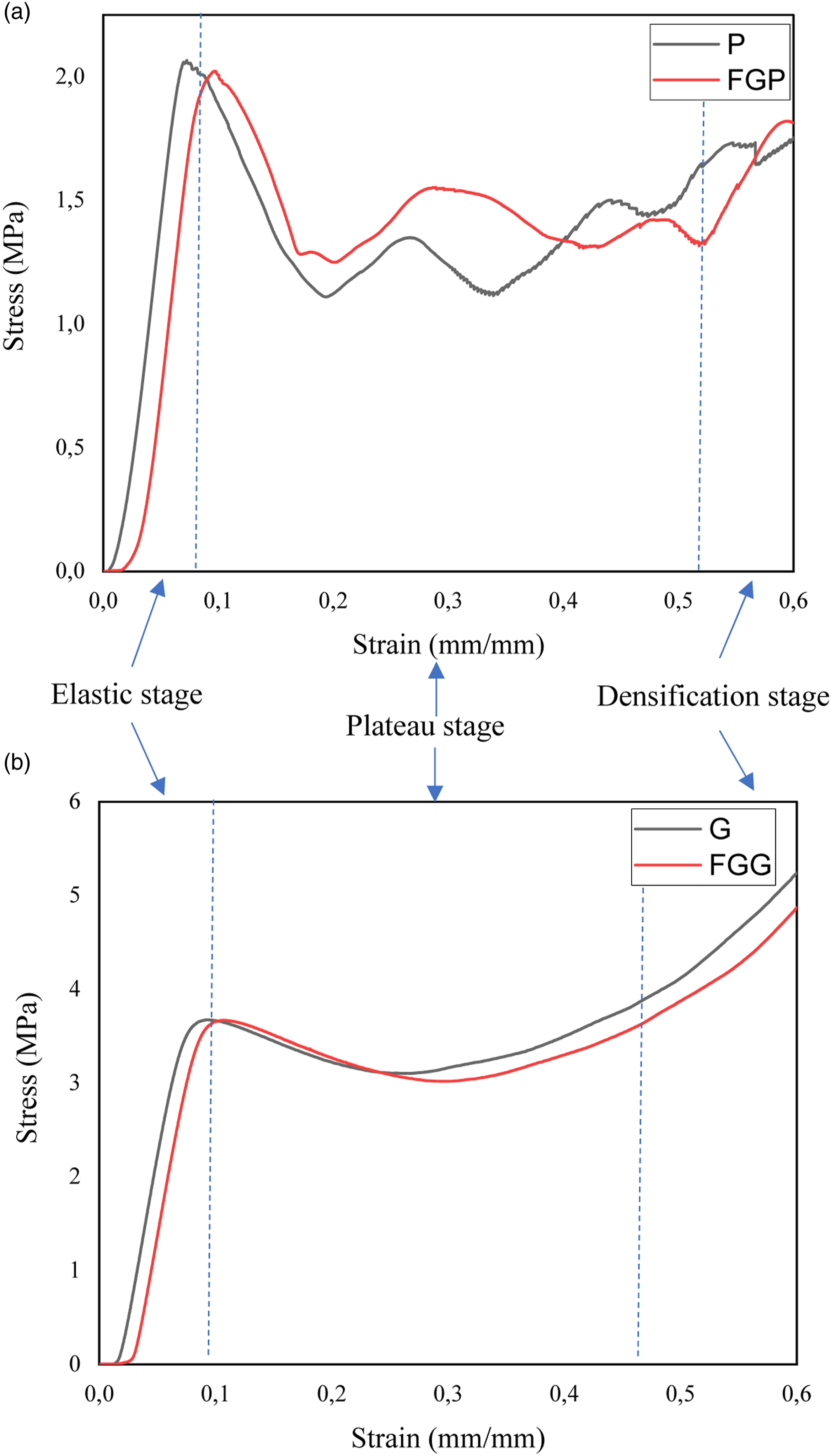
In the FG primitive lattice structure, plastic collapse occurred at 0.11 strain, which corresponds to 2 MPa stress. With the transition to the plateau stage, the tension increased and decreased continuously, as in the uniform primitive lattice structure. However, the stress value in the FG primitive lattice structure gradually increased continuously (Figure 6(a)). This means higher deformation resistance with reduced pore size. The condensation region, which started as a result of deformation of all unit cells, was found to be approximately 1.25 MPa stress and 0.52 strain.
Similar behavior was observed in the stress-strain curves for both gyroid structures (Figure 6(b)). While plastic collapse occurs in the uniform gyroid structure at a stress value of 3.63 MPa and at a strain value of 0.09; In the FG gyroid lattice structure, it occurred at a stress value of 3.61 MPa and a strain value of 0.105. Gyroid structures did not show significant flowing behavior compared to primitive structures. Different reasons for this situation have been discussed in the literature. Firstly, the occurrence of structural deterioration in the gyroid lattice structures is explained by their spread to the entire lattice structure and the closure of the formed cracks. 24 Another reason is that gyroid lattice structures show bending-dominant deformation behavior under stress values, which causes more ductile fracture behavior rather than sudden collapse.2,31 After the transition to the plateau stage, the fluctuation in stress values is not evident in the uniform and FG gyroid lattice structures, unlike the primitive lattice structures. As indicated in the deformation images given in Figure 5(c) and (d), it is experienced when the cracks occurring in the lattice structure immediately close with the contact of the unit cells. In addition, there are two faces vertical and parallel to the loading direction found in gyroid lattice structures. 24 While parallel faces increase the strength at the time of loading; vertical faces reduce the strength. This situation obscures the stress fluctuation in the plateau region of the gyroid lattice structures. Therefore, gyroid lattice structures behaved like a pure solid sample. With the end of the plateau phase, the stress value in the uniform and FG gyroid lattice structures ended with 5 MPa and 4.6 MPa, respectively.
FE results
FE tests were applied to predict the mechanical properties and deformation behavior of the uniform and FG lattice structures. Johnson-Cook damage criterion was used to observe the dynamic-mechanical response of the material and plastic deformation. The Johnson-Cook damage model is expressed as equation (3);
32

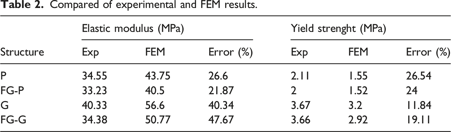
The results of the FEM compression test analysis applied to predict the mechanical properties and deformation behavior of the uniform and FG lattice structures are given in Figures 7 and 8 shows the stress-strain curves obtained experimentally and analytically to verify the reliability of the FEM. In addition, the relative errors of the predicted and experimental mechanical properties are given in Table 2. In general, when the experimental data and simulation results are compared, results are obtained with significant relative errors in the prediction of stress-strain curves for FEM uniform and FEM FG lattice structures. The prediction of elastic modulus and yield strength differed from the experimental data with relative errors of 47.67% and 26.54% for all truss structures, respectively. In particular, all FEM elastic modulus results were simulated higher than the experimental results. It is stated that these differences are due to the fact that the porosity and surface morphology of the lattice structures produced in the literature are not taken into account in the voxel-based model used in the numerical study.
33
It is also explained by the fact that it exhibits an earlier yielding behavior than it should be due to defects and structural errors during production. Finally, in the FEM and experimental results, between the uniform and FG lattice structures, the gyroid lattice structures showed higher mechanical properties than the primitive lattice structures. This shows that unit cell geometries are essential in determining the mechanical properties of lattice structures.
33
FEM analysis images obtained at different strain values; (a) uniform primitive, (b) FG primitive, (c) uniform gyroid, (d) FG gyroid. Comparison of lattice structures with FEM analysis results; (a) uniform primitive, (b) FG primitive, (c) uniform gyroid, (d) FG gyroid. Compared of experimental and FEM results.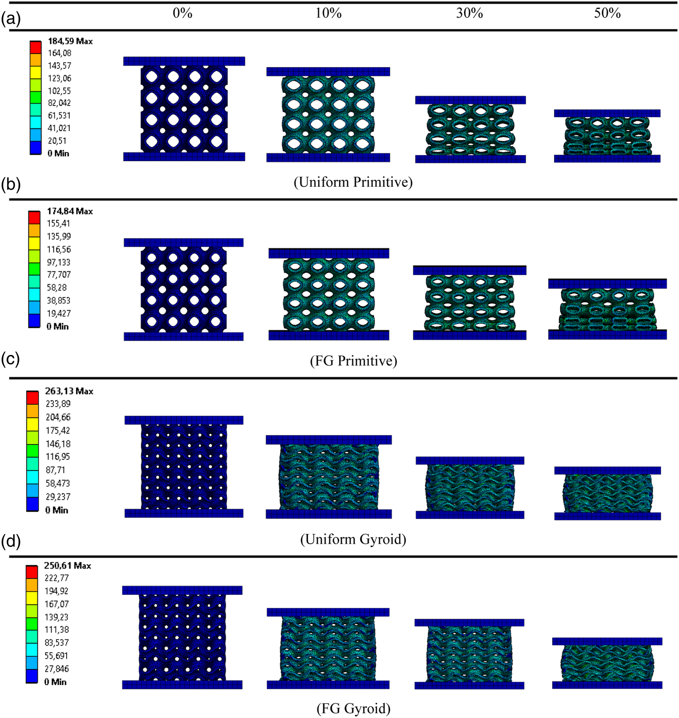
Similarities of experimental compression deformation behavior can be found with FEM. The mechanical properties of the lattice structure are significantly affected by the stress distributions occurring in the connection regions of the unit cells. Therefore, the stress distribution of the truss structures has been analyzed for each truss structure and is given in Figure 9. It has been found that the structural stress distribution clearly changes along the loading direction for both gyroid and primitive lattice structures. It has been analyzed that the deformation occurs in the form of layer-by-layer collapse with the change in the stress distribution. Stress distribution of three lattice structures in the loading direction; (a)uniform primitive, (b) FG primitive, (c) uniform gyroid, (d) FG gyroid.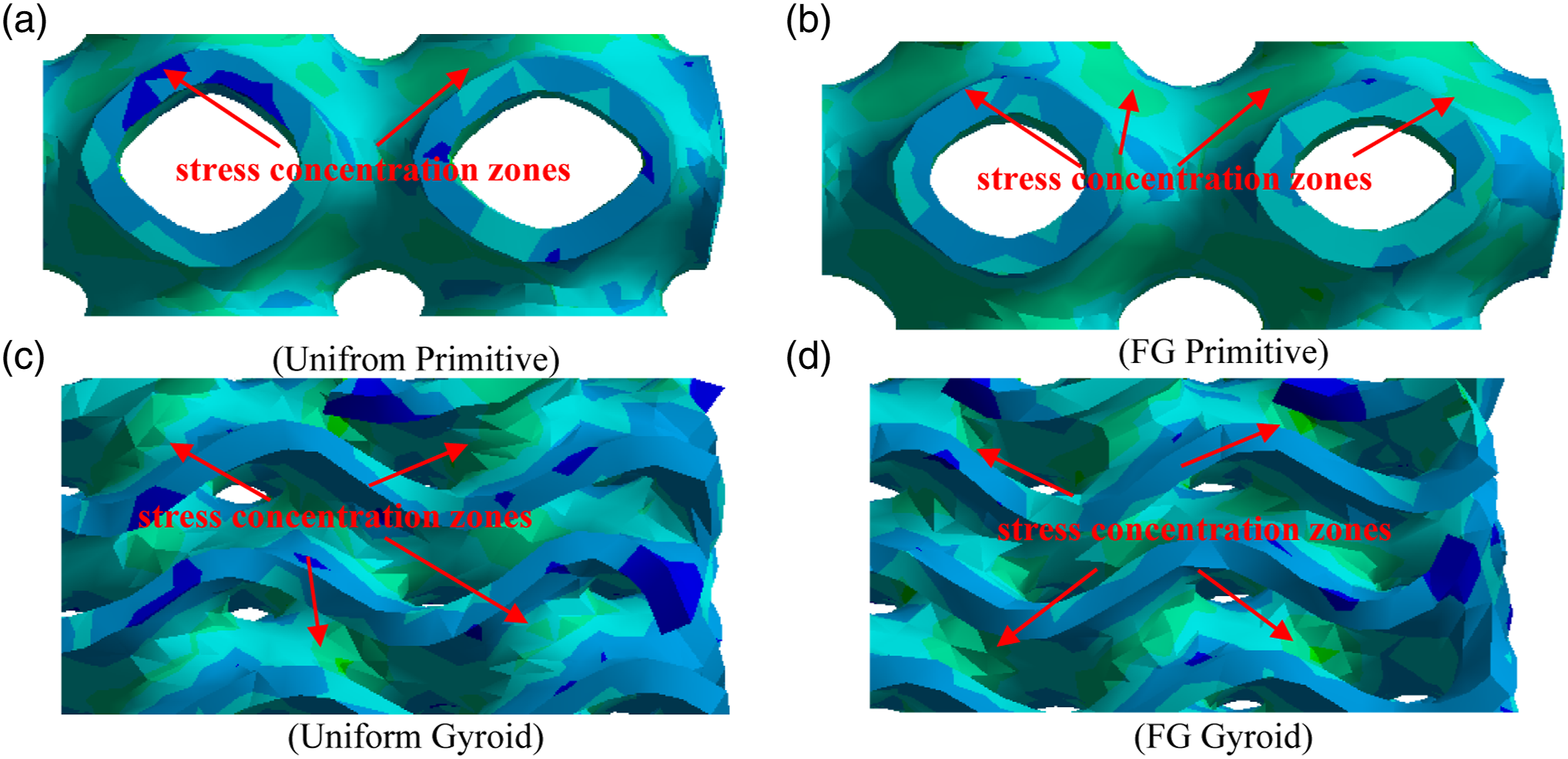
Energy absorption
As shown in Figure 6 in the stress-strain curves, the lattice structures absorb a large amount of energy until they are completely deformed. Figure 10 shows the energy absorption values of primitive and gyroid lattice structures calculated from the stress-strain curves obtained in uniform pore and FG pore sizes. In uniform and FG lattice structures, the gyroid lattice structure showed more energy absorption ability than the primitive lattice structure. This is due to the fact that the gyroid lattice structure does not show a significant yielding behavior while deforming, according to the stress-strain curves given in Figure 6(b). In addition, while the primitive lattice structure is deformed in the form of collapse layer by layer; The gyroid lattice structure is deformed by forming a slip band, and then all the layers are concentrated on each other, causing more energy absorption.
1
On the other hand, the energy absorption ability of the primitive lattice structure is relatively insufficient in the small strain stage, which reduces the energy absorption ability. Thus it exhibits a longer linear plateau region and consequently results in greater energy absorption. On the other hand, it was observed that there was no significant difference in energy absorption values in the uniform gyroid and FG gyroid lattice structure. Due to the deformation behavior of the gyroid lattice structure, the early contact of the unit cells with each other and the fluctuation in the stress obscure the area under the stress-strain curve. The strength of both lattice structures reached its highest value at approximately 0.45 strain. The energy absorptions calculated against this stress value in the uniform gyroid and FG gyroid lattice structures were approximately 187,377 MJ/cm3 and 199,058 MJ/cm3. The energy absorptions calculated against the strain value were approximately 82.82 MJ/mm3 and 83.26 MJ/mm3 in the uniform and FG primitive lattice structures. Energy absorptions of lattice structures.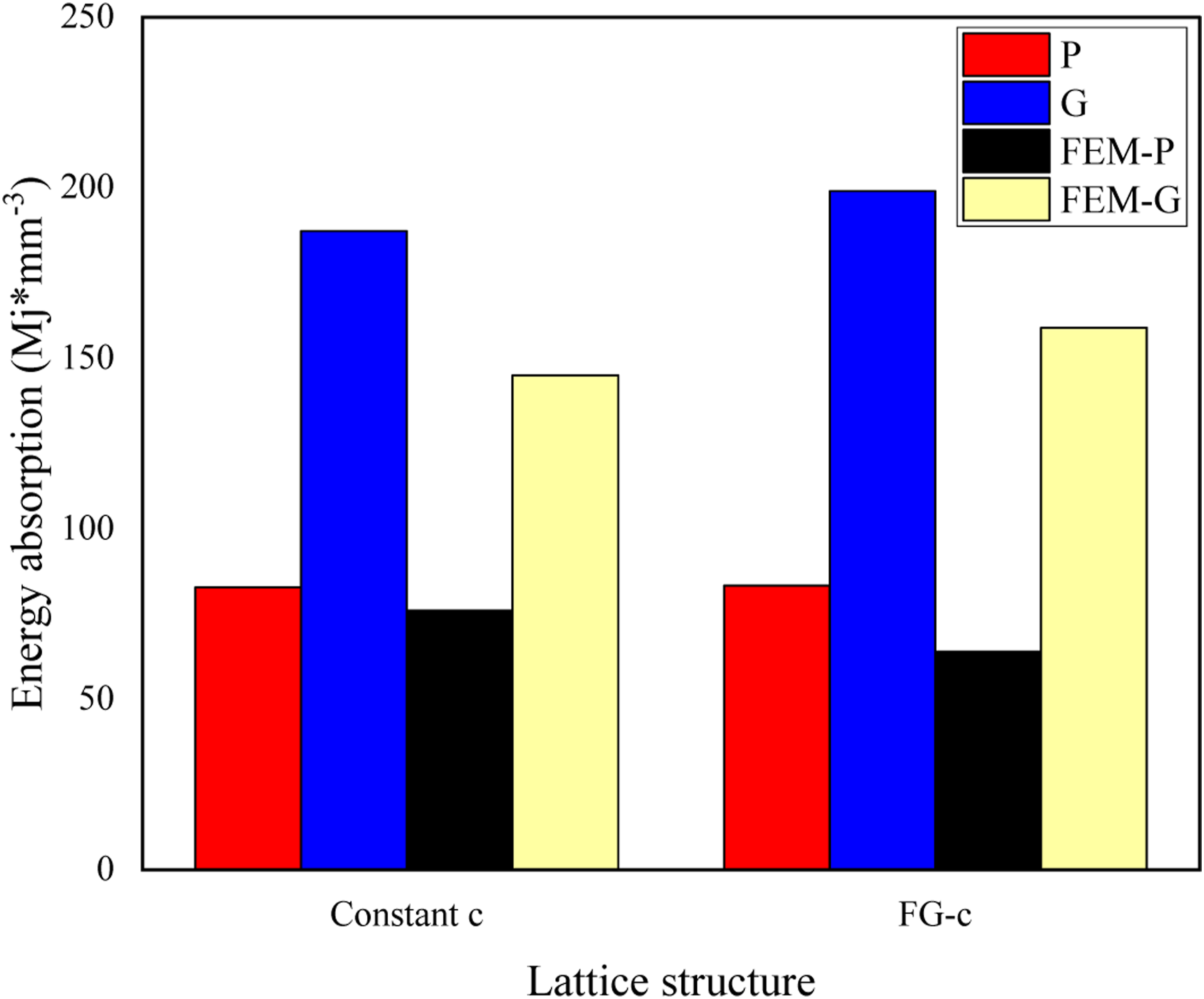
It is seen that both FG primitive and FG gyroid lattice structures absorb higher amounts of energy than uniform primitive and gyroid lattice structures. The energy absorption capacity of FG lattice structures relative to uniform lattice structures is mainly due to their distinctive deformation behavior during compression tests. 33 The FG gyroid lattice structure showed 6.41% more energy absorption ability than the uniform lattice structure. The degradation of the FG structure started from the layer with the lowest mechanical properties, then directly supported by the remainder, which eliminated high strength reductions and increased load bearing capability due to higher volume fractions. 33 It was determined that there was no significant difference between the amount of energy absorption in FG primitive and uniform primitive lattice structures. As shown in Figure 6(a), the stress value of the FG primitive lattice structure at a strain value of about 0.4 showed a sudden downward trend. Therefore, the end of the plateau region and the beginning of the densification region exhibited less energy absorption than the uniform primitive lattice structure. In addition, the energy absorption results obtained as a result of FEM analysis are given in Figure 10. According to the energy absorption results calculated with the experimental data, the deviation was measured 8.9% in the primitive lattice structure, 28.53% in the FG primitive lattice structure, 28.96% in the gyroid lattice structure and 25.15% in the FG gyroid lattice structure.
Conclusion
In this study, uniform and FG TPMS-based primitive and gyroid lattice structures were designed and produced using the FDM method. Then, quasi-static compression tests and FEM analysis were applied to determine the compression response and energy absorption capabilities. Obtained results can be listed as follows: 1. It has been observed that the mechanical performances of the lattice structures depend on the unit cell shapes and sizes. The gyroid lattice structure showed more energy absorption and yield strength than the primitive lattice structure. 2. The deformation behavior of the primitive lattice structures was in good agreement with the conventional lattice structures, while the gyroid structures exhibited inconspicuous cracks and collapses under compression. 3. In the deformation images, while the primitive lattice structure is deformed layer by layer, the gyroid lattice structure is deformed by the formation of a shear band after a certain strain value. 4. The compressive stress in FG primitive lattice structures gradually increases, reaching the maximum peak stress layer by layer. Uniform and FG gyroid lattice structures have equal peak tension and plateau tension. 5. It has been observed that the ability to absorb energy increases with the FG of porosity. 6. Significant changes were observed in the energy absorption of the lattice structures with the application of FG. The energy absorption value of the uniform gyroid lattice structure was 57% higher than the uniform lattice structure, and the FG gyroid lattice structure was 58% higher than the FG primitive lattice structure.
Gyroid lattice structures show good potential in terms of mechanical properties and energy absorption. However, in this study, only uniform and uniaxial FG designed lattice structures are focused. In future studies, with the development of FDM technology, it is planned to produce triaxial (x,y,z) FG designed lattice structures and investigate their mechanical properties. Furthermore, the effect of FDM production parameters (nozzle diameter, printing speed, fill rate etc.) on the mechanical properties of the lattice structures can be considered.
Footnotes
Declaration of conflicting interests
The author(s) declared no potential conflicts of interest with respect to the research, authorship, and/or publication of this article.
Funding
The author(s) disclosed receipt of the following financial support for the research, authorship, and/or publication of this article: This research was supported by Inonu University BAP (project number: FDK-2021-2617).
Data availability
All data generated or analysed during this study are included in this published article (and its supplementary information files).