
Abstract
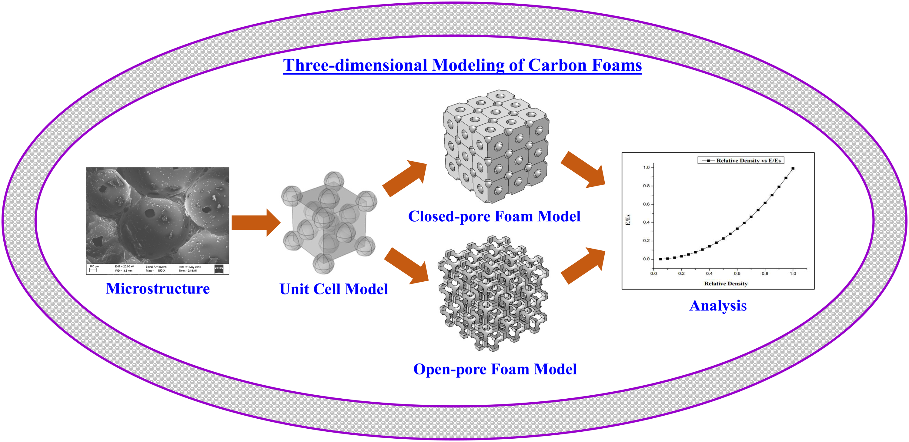
Carbon foams are versatile materials with a wide range of properties, making them suitable for many engineering applications. Like other cellular solids, the topology of carbon foam structures significantly influences their mechanical properties. To accurately assess the mechanical properties of the carbon foam, it is imperative to model the foam structure in a manner that closely resembles the foam’s actual three-dimensional geometry. The goal of this study is to accurately show the actual topology of carbon foams by using a computer model to capture the three-dimensional geometry of carbon foam based on real microstructures. Subsequently, finite element analysis (FEA) is performed to determine the effective mechanical properties, such as Young’s modulus and Poisson’s ratio. We further compare the FEA results with previously established open- and closed-cell models documented in the literature. The findings show how microstructural topology and relative density affect the mechanical properties of carbon foams, such as Poisson’s ratio and Young’s modulus. The findings indicate a close agreement between the finite element outcomes and the results documented in existing literature.
Introduction
The demand for structural engineering materials that possess high strength, low weight, and affordable cost has prompted advancements in the realm of advanced materials technology. Among these materials, carbon and carbon-based materials have emerged as notable contenders. Carbon foams are a type of cellular material that possess several unique characteristics. These include their affordability, low weight-to-volume ratio, ability to withstand high temperatures (up to 3000°C in an inert atmosphere), increased surface area, improved energy absorption capabilities, and versatile thermal and electrical properties.1,2 Over the past few decades, there has been a significant increase in the attractiveness of these materials due to their extensive prospective uses in many sectors such as aerospace, military, offshore industries, power generation, and other commercial domains. 3 According to Tsyntsarski et al., 4 carbon foams, as well as other carbon and graphite materials exhibiting low coefficient of thermal expansion (CTE) and high emissivity, can be considered as the optimal choice for utilization in both low and high-temperature settings. The inclusion of features such as thermal insulation and electrical conduction renders these materials a more favorable choice for thermal management systems.4,5 The hierarchical porous nature of carbon foam enables it to effectively absorb both partial and whole sound waves. The acoustic properties of carbon foams make them suitable for use as materials in sound absorption and sound fidelity systems.6,7 Various applications utilize sound absorption, such as aviation ventilation ducts, compressors, power units, automotive panels, and maritime applications, among others. Earphones, microphone covers, and stereo speaker grilles are among the applications commonly found in sound fidelity systems. 6 Carbon foams have a wide range of uses, such as their use as filters and devices for regulating fluid flow. They are also utilized as catalyst supports, materials for vibration damping, storage media, fuel cells, biomedical prostheses, internally cooled shape memory actuators, artificial skin, and non-slip surfaces for trays, tables, and floors. 6 Based on the findings of certain researchers and proponents of materialism, it is posited that carbon foam, as an emerging material, has the potential to supplant traditional materials including wood, ceramics, plastics, glass, rubber, and metals. 5
The mechanical properties of carbon foams must be thoroughly studied in order to be used in trustworthy structural applications. The characterization of mechanical properties in cellular solids is challenging due to the unique combination of features exhibited by cellular foams, including bulk material properties, relative density, pore size distribution, and cell size distribution, as well as the complicated three-dimensional topology of cell shapes. 8 Carbon foams, like polymeric or metallic foams, exhibit topological sensitivity, meaning that their mechanical properties may be modified by manipulating factors such as the micro-geometry of the cells, the relative density of the foam, and the shape of the cross-sections of the struts and ligament material. 9 To comprehensively assess the mechanical and thermal capabilities of a foam material, it is imperative to accurately describe the topological characteristics of its three-dimensional structure, closely resembling that of real foam. Therefore, it is imperative to integrate microstructural characteristics of carbon foams into the mechanical modeling process.
Several researchers have conducted experimental investigations on the impact of microstructure on the compressive response of carbon foams.10–14 The inability to isolate and study individual morphological parameters is a result of the intricate nature of manufacturing techniques and experimental testing procedures. The utilization of a specialized computational methodology that systematically incorporates intricate morphological aspects in a regulated manner can prove to be advantageous in this particular context. One significant benefit of employing numerical models at the micro-scale is the ability to explore the inherent connection between the deformation mechanisms of individual cells and the overall mechanical behavior observed at the macro scale.
Foam mechanical models typically rely on cell structure models. One such method for analyzing mechanical properties is the application of dimensional analysis. 15 This approach allows for the determination of the foam properties based on the relative density while disregarding the influence of cell geometry. However, it is necessary to know the constants associated with cell geometry by fitting experimental data.
One of the approaches employed in the modeling of foams involves the replication of a unit cell comprising the struts of the cell.9,16–18 This is achieved through the application of finite elements or structural mechanics techniques. In this approach, actual foam structures are approximated by employing uncomplicated cell geometries that closely resemble the precise cell geometry, such as bubble models, cubic, tetrahedral, or tetrakaidecahedral unit cell models. Additionally, to enhance computational efficiency, numerous models utilize periodic boundary conditions, wherein a representative volume element (RVE) is replicated to represent the entirety of the foam structure. 19 Provided that the mechanical properties of the solid are known, this approach can yield a comprehensive characterization of the foam’s behavior under stress or strain.
One potential strategy for introducing randomness into the foam model is the utilization of a random tessellation technique.20–23 This technique involves the generation of random open or closed-cell foam models by the utilization of randomly dispersed seed points in three-dimensional space. The subsequent determination of the self-regions associated with each seed point leads to the formation of random cell aggregation. An alternative methodology for modeling foam structures involves the utilization of micro-tomography instruments, which enable the digital scanning of actual micro-structures of foams. Subsequently, discrete finite element models can be generated based on these digital scans.24–27 The utilization of finite element modeling (FEM) is a prevalent method employed to investigate the impact of microstructural geometry of foam on its macroscopic properties.19,24,28,29 The Finite Element Method (FEM) employs a variational version of the linear elastic equations and determines the solution by minimizing the elastic energy using a rapid conjugate gradient method.
Numerous numerical formulas have been produced utilizing the aforementioned methodologies for both open and closed-cell foams within a restricted relative density range.15,16,19,21–23 Nevertheless, a restricted number of models can be efficiently utilized across the entire range of foam relative densities. Moreover, it is worth noting that neither of the models can be effectively utilized for accurate prediction of the mechanical properties of both open and closed-cell foams.
This study used a Finite Element Method (FEM) to assess the elastic characteristics of simulated carbon foam models across various relative density levels. The design of the foam models is derived from the authentic microstructures observed in carbon foams. Subsequently, a finite element stress analysis is conducted in order to ascertain the elastic characteristics of the carbon foam across various densities. Subsequently, the FEA outcomes are compared with existing open and closed-cell models documented in literatures. The findings illustrate the influence of microstructural topology and relative density on the mechanical characteristics of carbon foams, encompassing Young’s modulus and Poisson’s ratio. The obtained results have the potential to be utilized for predicting the properties of carbon foams, provided that their structure bears a resemblance to one of the established models. Additionally, these findings can be effectively employed for the appropriate interpretation of experimental data.
Modeling of the carbon foam
Design of the unit cell
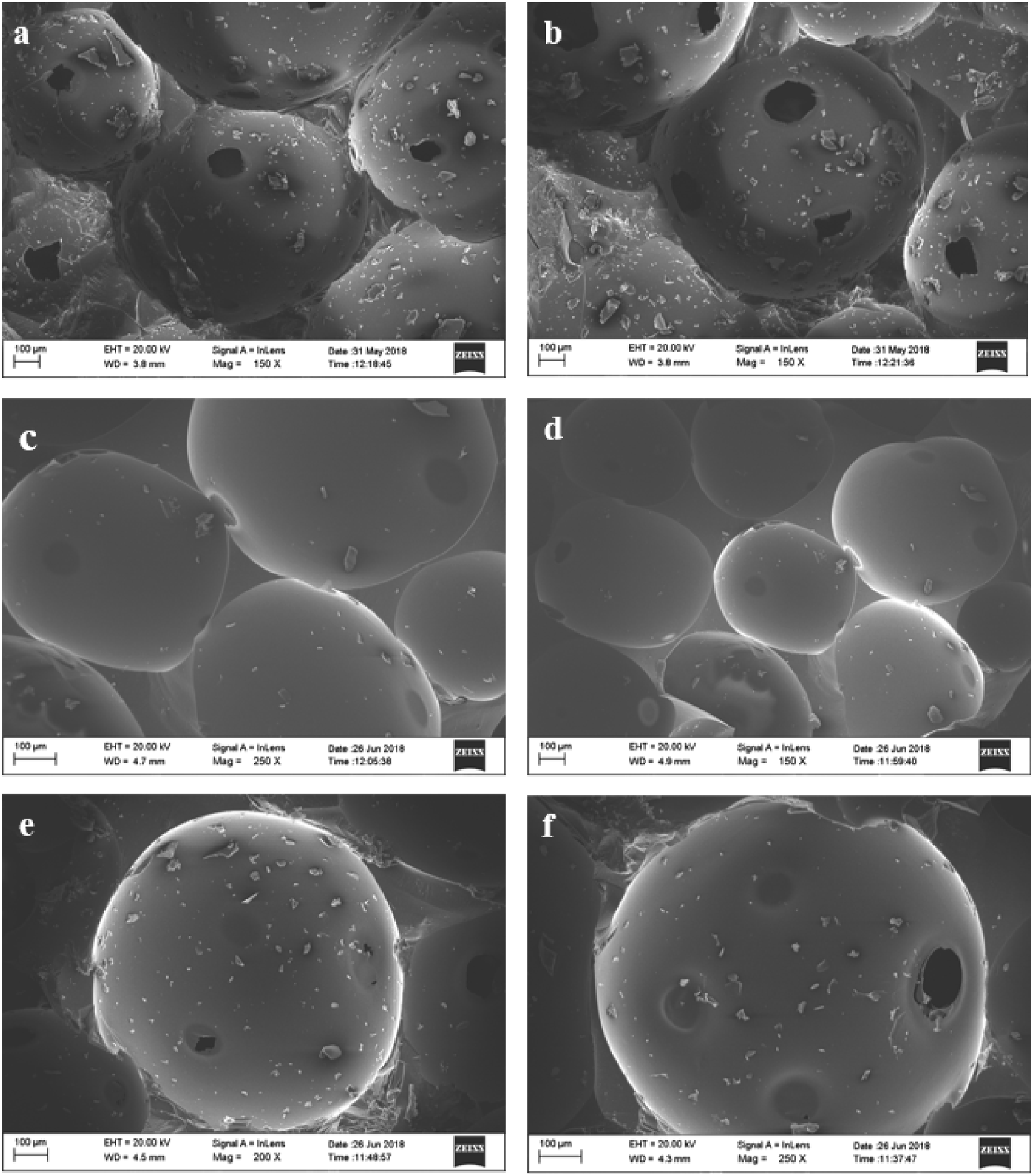
In our prior research endeavor, we successfully produced carbon foam from coal tar pitch by the utilization of an ambient pressure foaming technique, employing sodium bicarbonate as a solid foaming agent. The scanning electron microscopy (SEM) pictures of the carbon foam samples are depicted in Figure 1. Subsequent observations were recorded based on these images. 1. The foaming process is similar to the bubble formation as proposed by Plateau.
30
2. The foam structure consists of a combination of closed and open pores. 3. The shape of the pores is nearly spherical. 4. The foam cells exhibit a non-homogeneous distribution of pore sizes and are unevenly distributed within the foam structure FESEM microstructure of foam produced from coal tar pitch; (a, b) foam before carbonization, (c, d) foam sample after carbonization, (e) single closed spherical pore, and (f) single open spherical pore.
Based on the aforementioned data, it can be inferred that the pore diameter and pore position are the key factors that determine the presence of closed or open pores, under the assumption of a uniform pore size throughout the structure. When all the nuclei responsible for foaming are activated concurrently, the initial phase of nucleation involves a closed foam structure that gradually transitions into an open foam structure as the pore size expands.
After conducting microscopic examinations on the carbon foam material, it was determined that a unit cell with a hybrid cubic (HBC) structure would be utilized (as shown in Figure 2). This structure incorporates a combination of body-centered cubic (BCC) and face-centered cubic (FCC) locations for arranging the spherical voids within the unit cell. Different levels of porosity and porous structures, including open pores, closed pores, and mixed pores, were achieved by varying the radius of the void. Formulation of the proposed unit cell for the analysis.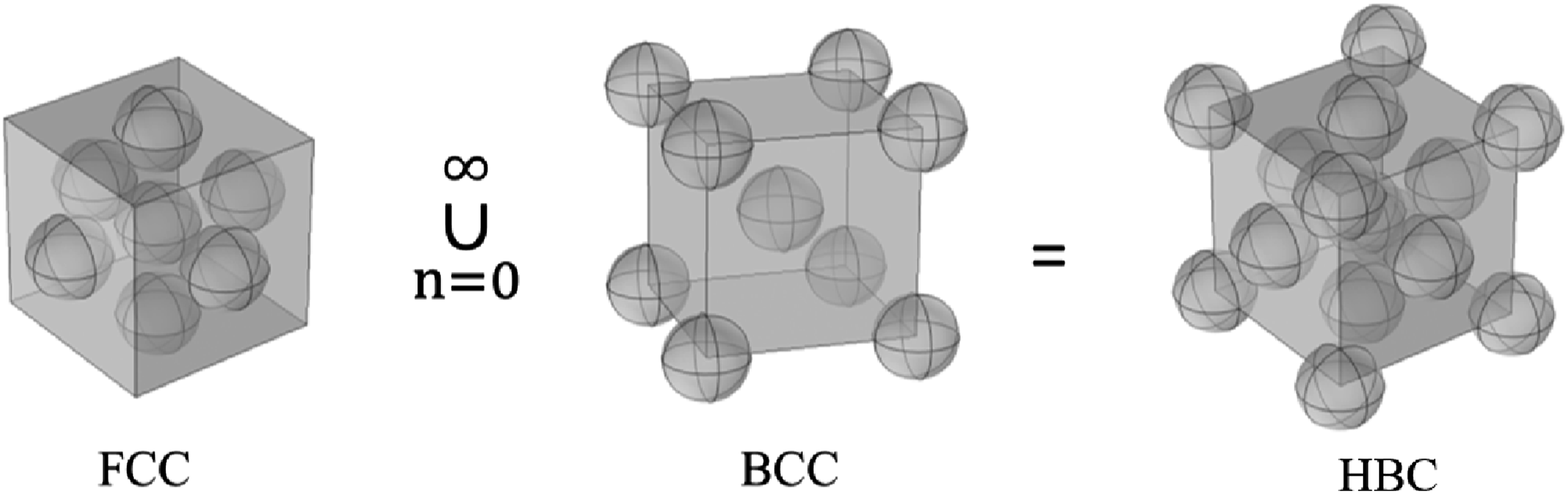
Generation of the foam structure
The 3D carbon foam models were generated using the COMSOL Multiphysics software. The steps are represented in Figure 3. Steps for generation of 3D foam structure by COMSOL Multiphysics.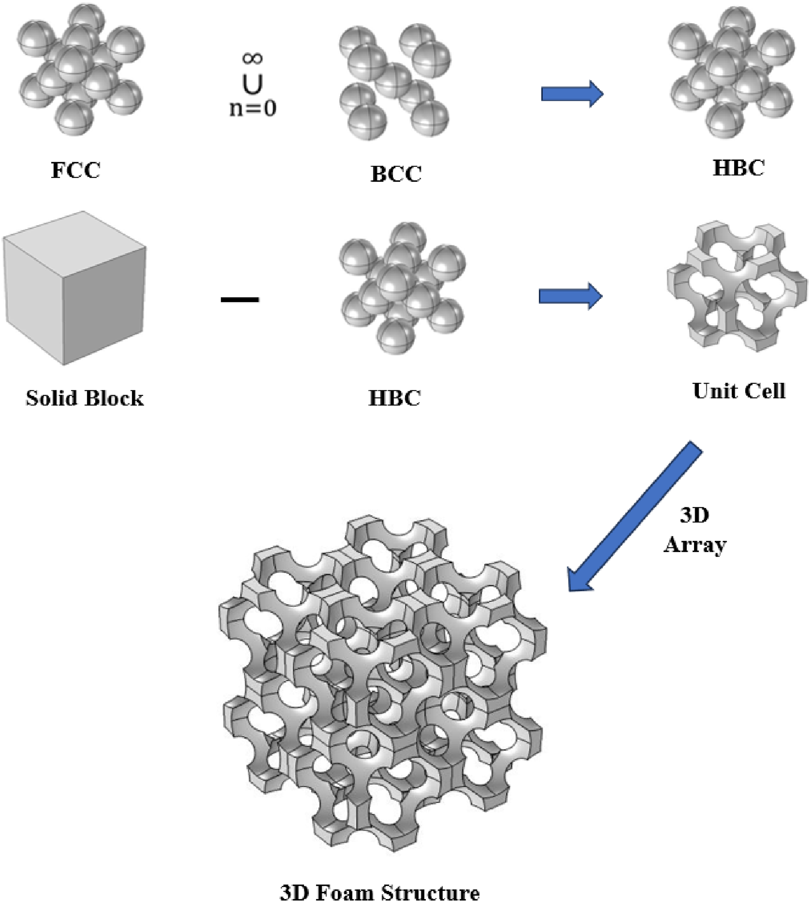
The evolutionary process of foam structures
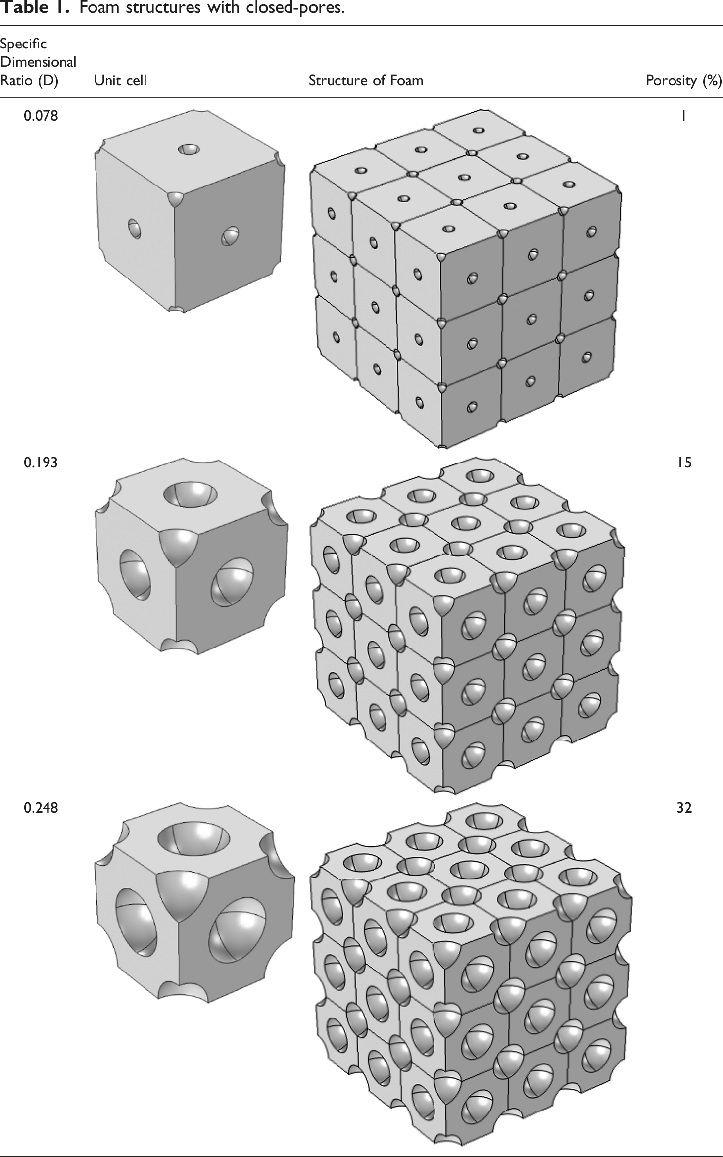
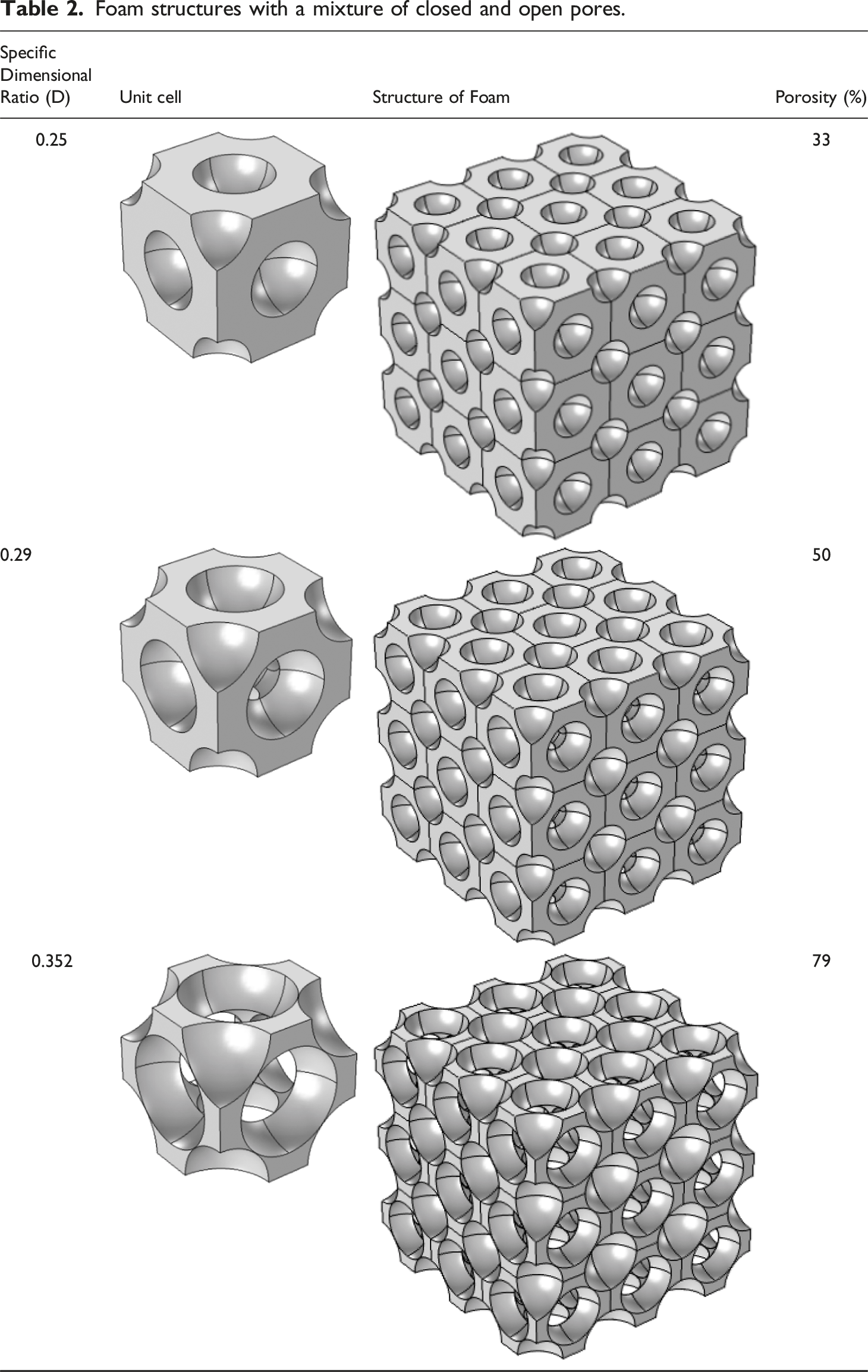
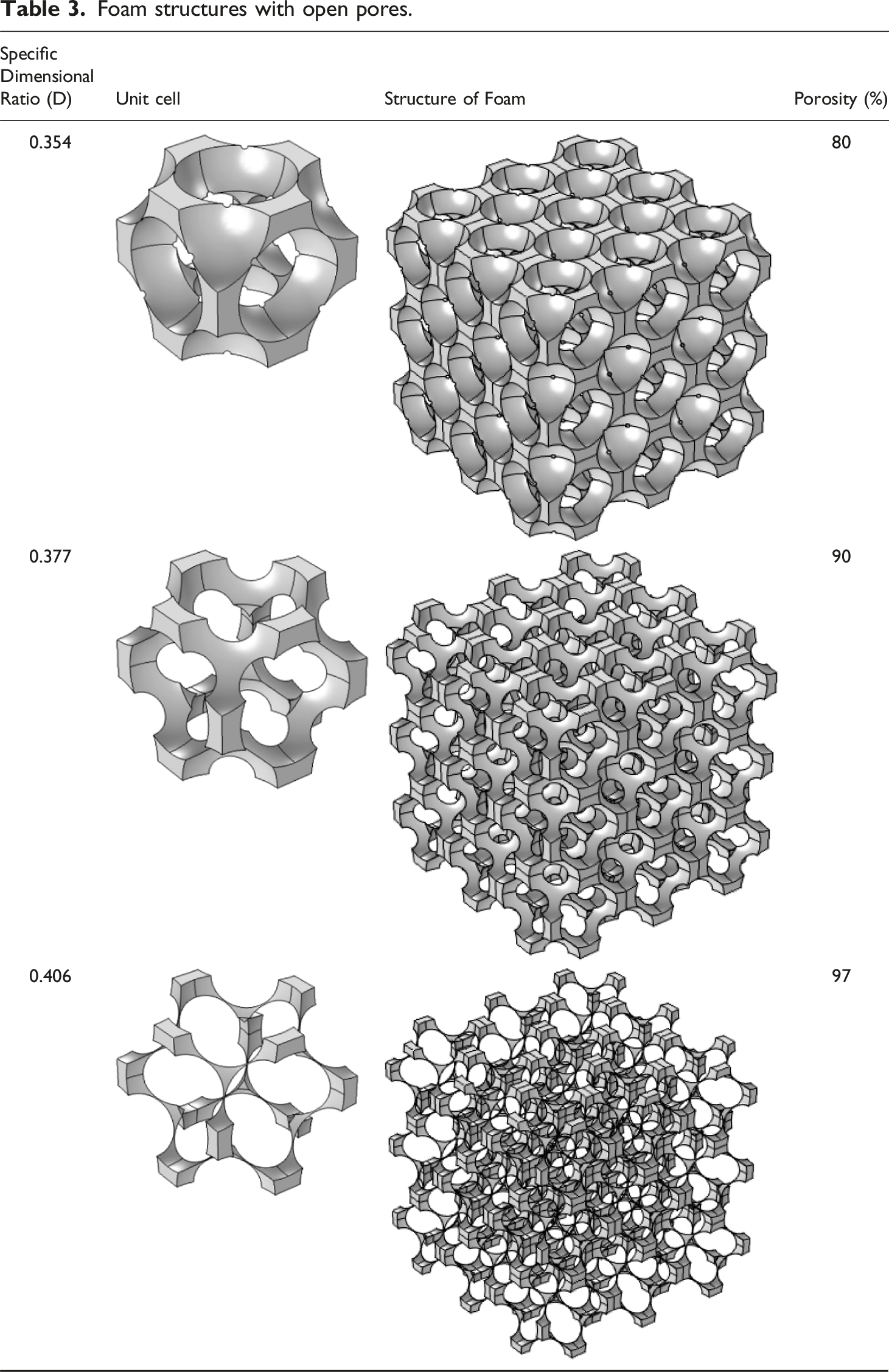
By keeping the unit cell length (a) constant and varying the pore radius (R), different pore configurations can be observed. These configurations range from closed pores to open pores, with an intermediate stage where both closed and open pores coexist. In this analysis, we define the specific dimensional ratio (D) as the ratio of the pore radius to the unit cell length, representing the porosity (φ) and relative density (ρ) of foam structures.
Foam structures with closed-pores.
Foam structures with a mixture of closed and open pores.
Foam structures with open pores.
Estimation of the relative density of the foam structure
Closed pore structure (high-density foam)
In the case of a closed pore structure, where each pore is isolated, the total volume of the void can be determined by summing the volumes of all the individual spherical voids.
The total no of spheres
So, the volume of the void
And, the volume of the cube,
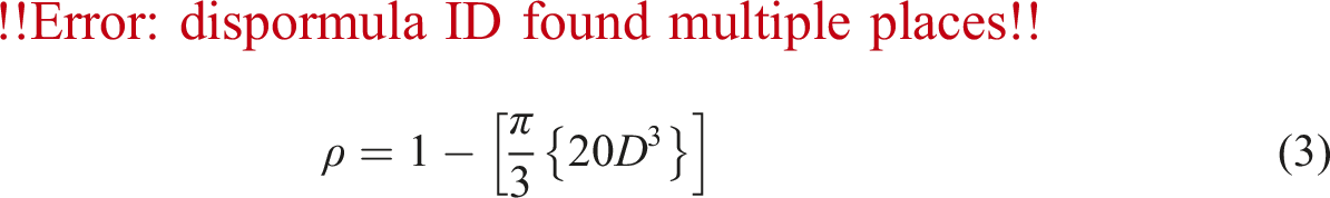
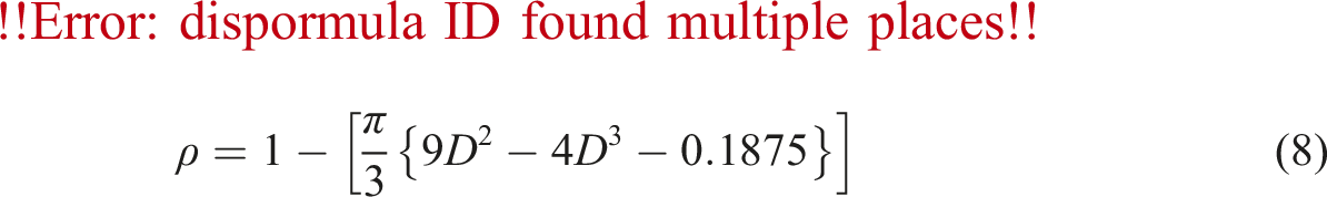
The porosity of the closed-foam structure is given by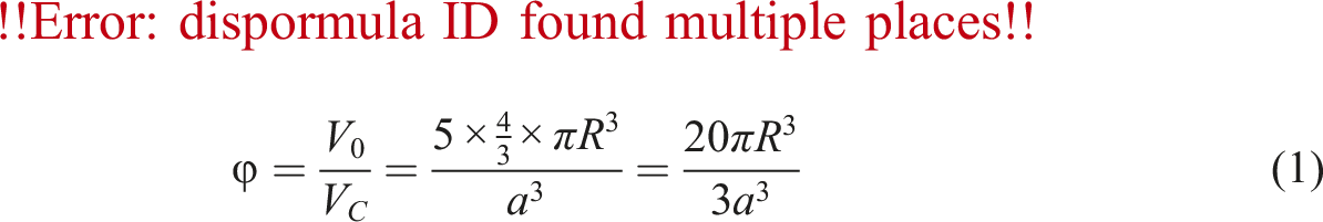
Hence the relative density of the closed-foam structure is given by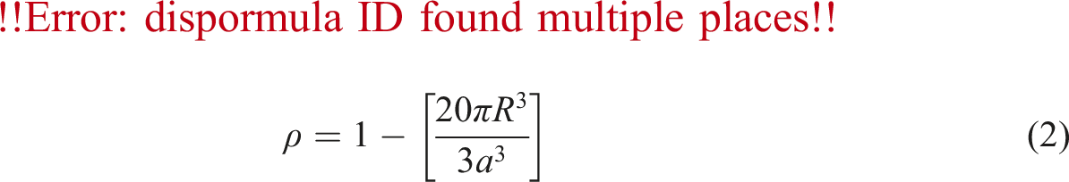
Structure with mixed of pores (moderate density foam)
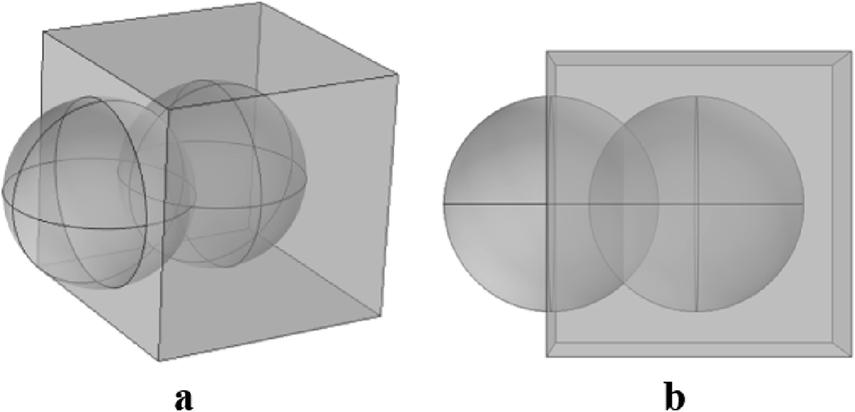
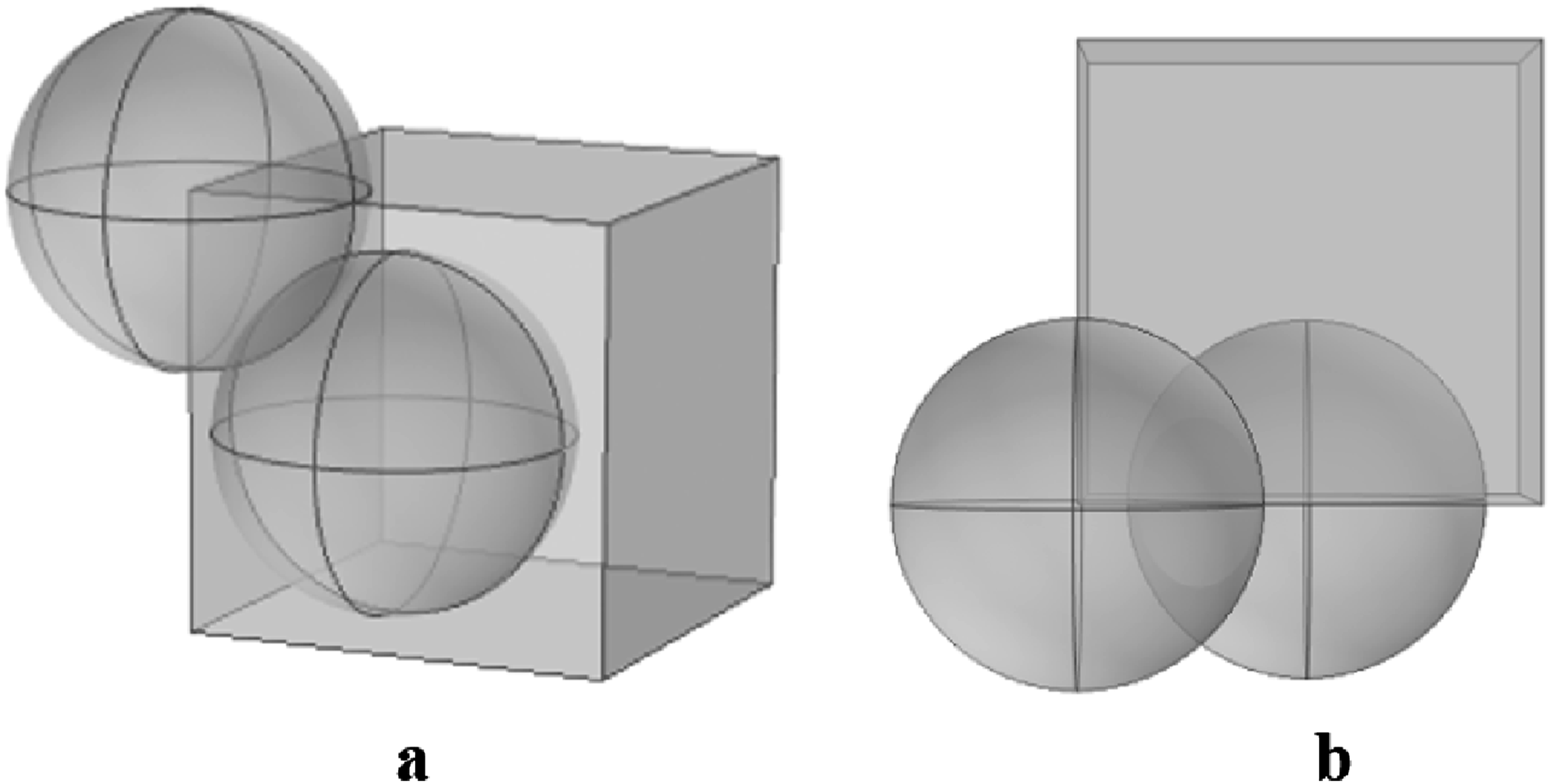
Here some of the pores are remained closed while others are converted into open form. Each sphere at the face center is overlapped with the sphere at the body center. The volume of the void is calculated by subtracting the overlapped spherical lens part (shown in Figure 4) from the volume of the spherical voids. Spherical lens formed by overlapping of two spheres.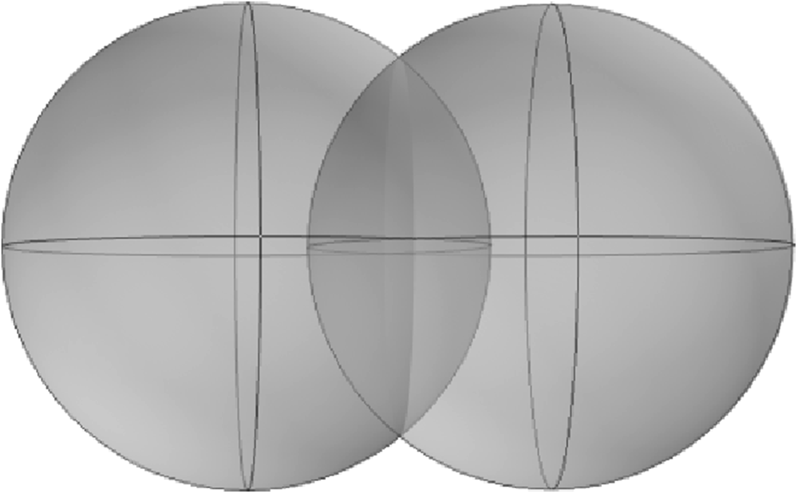
At first, the volume of a spherical lens formed by overlapping of two spheres is calculated as:
But the distance between two spheres centered at face center and body center; Overlapping of face centered and body centered spheres: (a) side view, (b) top view.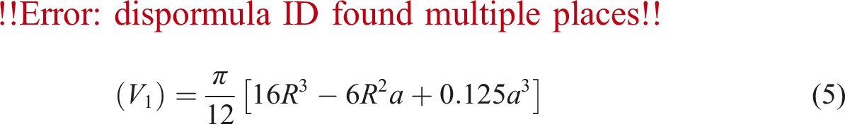
Volume of the void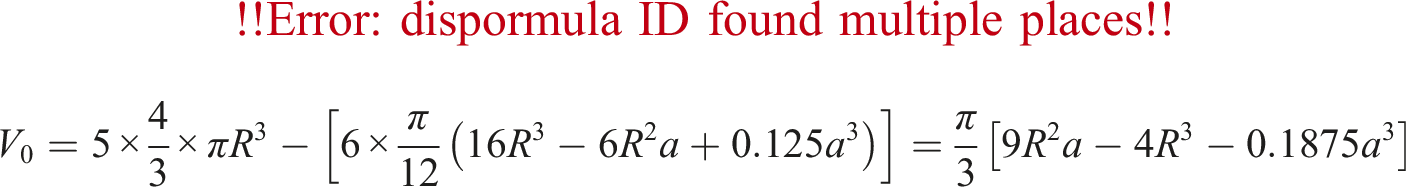
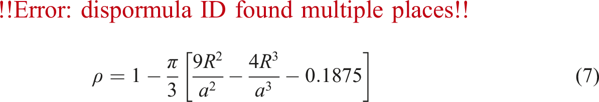
The porosity of the closed-foam structure is given by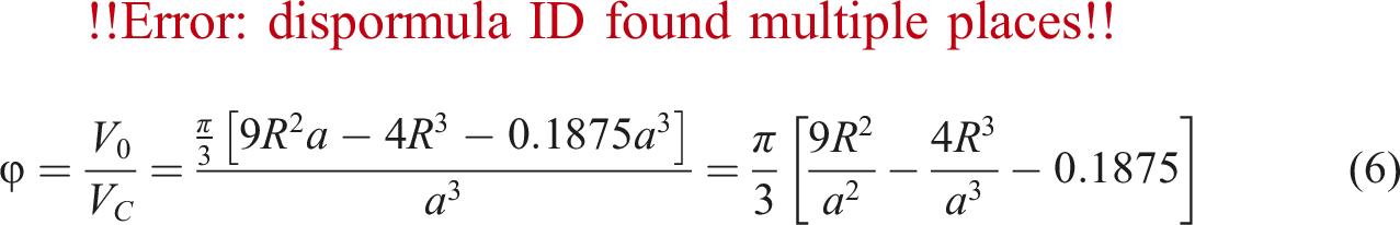
Open pore structure (low density foam)
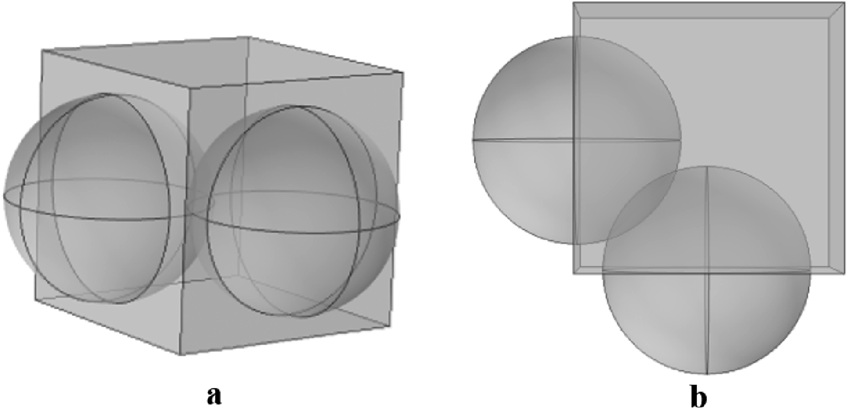
In the present instance, all of the voids are interconnected with adjacent voids, resulting in a collective structure that exhibits an open pore system. Each sphere located at the face center of the structure is in contact with 14 neighboring spheres, consisting of 8 face-centered spheres, 4 corner spheres, and 2 body-centered spheres. On the other hand, each sphere positioned at the corner of the structure is in contact with 12 neighboring spheres, all of which are face-centered. The sphere at the body center is overlapped exclusively with six spheres at neighboring six faces. The determination of the void volume entails the subtraction of the volumetric contribution of the overlapped spherical lens component from the total volume of the spherical voids.
The formula for the determination of the volume of a spherical lens generated by the overlapping of face-centered and body-corner spheres as shown in Figure 6, is given as follows: Overlapping of face centered and body corner spheres: (a) side view, (b) top view.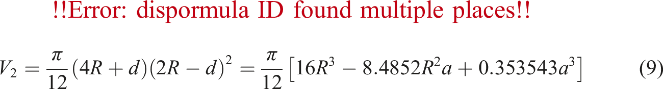
The calculation of the volume of a spherical lens resulting from the overlapping of two face-centered spheres, in Figure 7, is as follows: Overlapping of two neighbouring face centered spheres: (a) side view, (b) top view.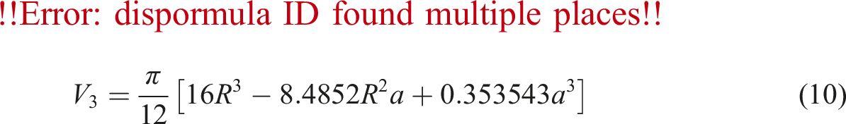
The calculation of the void volume is based on the presence of 24 spherical partial lenses, each contributing one-half of the total volume, and 12 spherical partial lenses, each contributing one-third of the total volume.
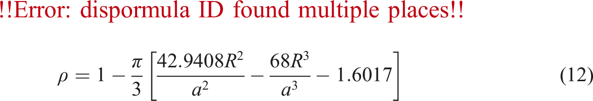
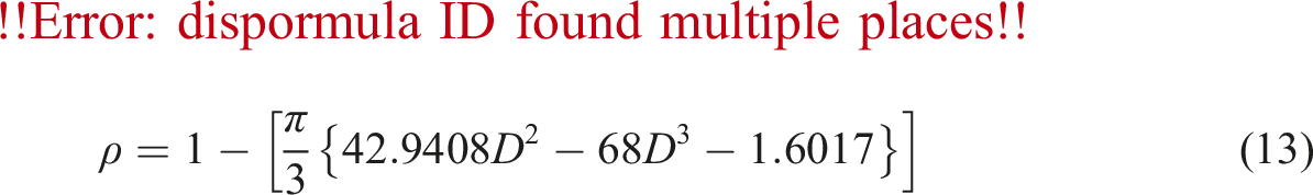
So, the volume of the void
The volume of the void
The porosity of the closed-foam structure is given by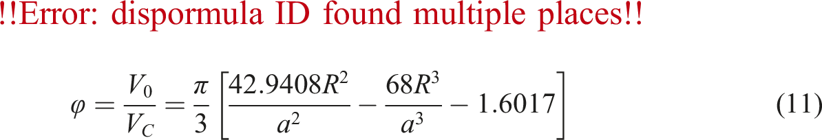
Therefore, we can use equations (1), (6), and (11) to determine the porosity of closed pores, mixed pores, and open-pore carbon foam structures, respectively. Similarly, we use equations (3), (8), and (13) as tools to determine the relative density of closed pores, mixed pores, and open-pore carbon foam structures, respectively. Figure 8 illustrates the specific dimensional ratio (D) in relation to both porosity (φ) and relative density (ρ) of the foam structure. Relation of specific dimensional ratio with relative density and porosity for carbon foams.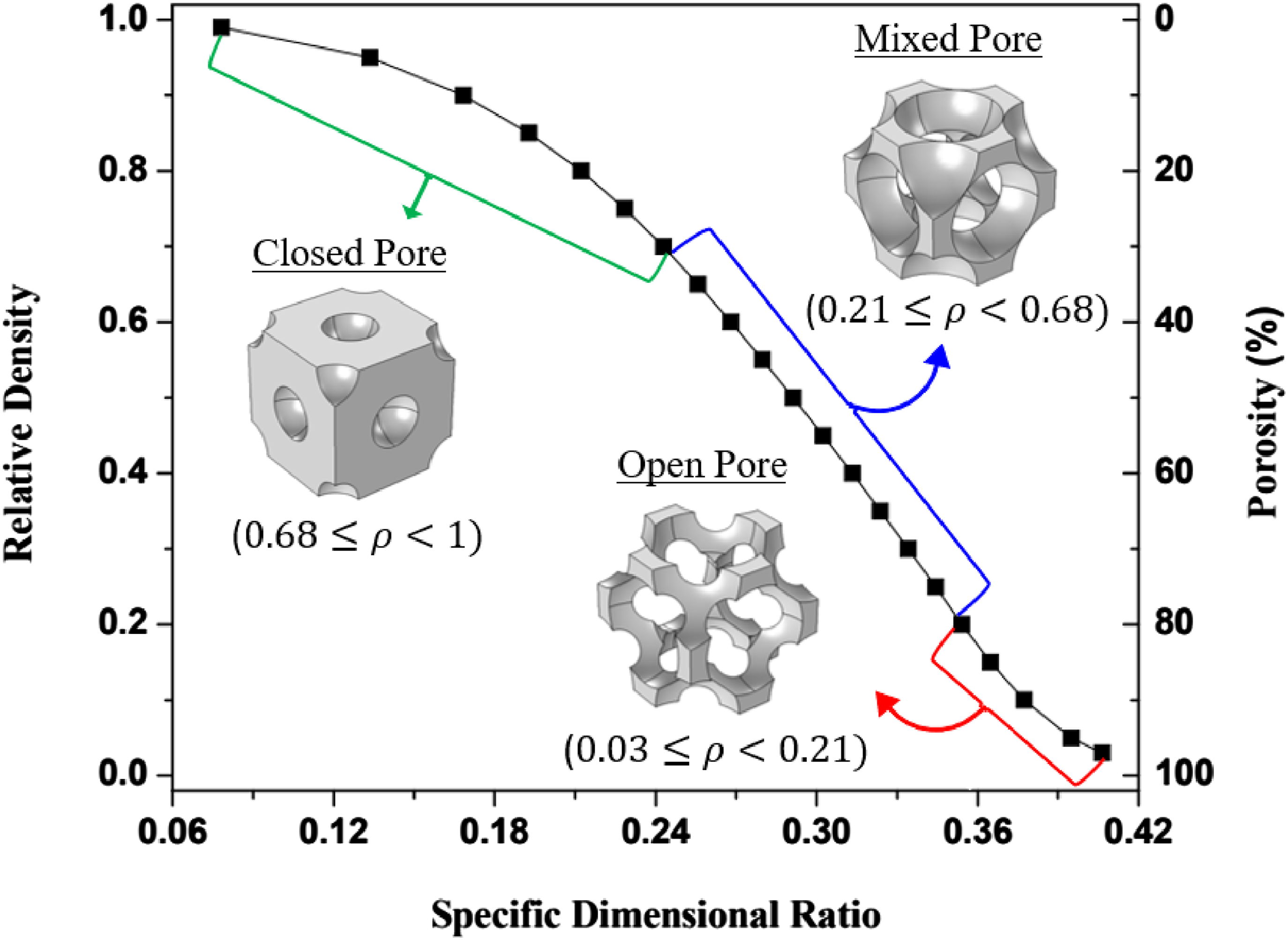
However, the current model is classified as an open-cell foam structure (
Prediction of mechanical properties by using finite element models
Methodology and simulations
The FEA technique is used to analyze the carbon foam structure under mechanical load. The model that is being used is linear elastic, it uses constant material characteristics, and it only takes into consideration very small deformations. Consequently, it does not exhibit significant deformations or geometric discontinuities, which is consistent with the brittle characteristics of carbon foams. The study results enable the determination of the effective Young’s modulus and Poisson ratio of the carbon foam structure.
The carbon foam’s 3D solid model is placed between two solid metallic plates to enforce boundary conditions. It is assumed that there is a rigid mechanical contact between the carbon foam and the metallic plates, without any penetration, in the direction perpendicular to the surface. The carbon foam and the metallic plates are connected by a mechanical connection that is specifically engineered to reduce friction in the tangential direction, enabling unrestrained deformation. In addition, a friction coefficient of 0.2 was defined between the carbon foam structure and metallic blocks.
31
The force equilibrium equation governs the displacement field in the assembly, which consists of the metallic plates and the carbon foam, as follows;
The solid phase of the carbon foam exhibits constitutive behavior that is characterized by a linear elasticity model, relating stress and strain, as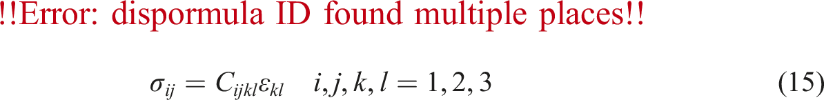
The variables
The mechanical analysis is subject to the following boundary conditions: ➢ The lower bottom surface of the lower solid plate is completely restricted. ➢ The normal directions of two neighboring sides of the carbon foam have constraints to prevent translation. ➢ The normal directions of two neighboring sides of the upper solid plate have constraints to prevent translation. ➢ A uniform compressive load is applied perpendicular to the top surface of the upper solid plate.
To ensure consistent boundary conditions on the upper and lower surfaces, the carbon foam structure is sandwiched between two solid metallic plates. The assembly was generated using the COMSOL Multiphysics software platform. It includes a 3D model of carbon foam structure and two metallic plates. The finite element analysis (COMSOL Multiphysics) is employed to solve equation (14) using the ‘Solid Mechanics’ module. Following generating the foam model, essential finite element methods such as material selection, body meshing, and boundary condition specification are applied. The isotropic nature of the bulk material of carbon foam is presumed, despite the presence of an anisotropic cell ligament structure. The Young’s modulus (E) and Poisson’s ratio (ν) are assumed to be 15.61 GPa and 0.33, respectively, for the bulk material. 32
The foam model partition function inside the COMSOL software was employed to facilitate the division of the foam core volume into simpler components, hence enabling the straightforward meshing of the entire body. Foam structures employ tetrahedron elements (as shown in Figure 9) due to their intricate three-dimensional topology. One dimensional load in z-direction is applied; the normal stress Finite element discretization of 3D carbon foam structure sandwiched with metallic plates; open cell (left), closed cell (right).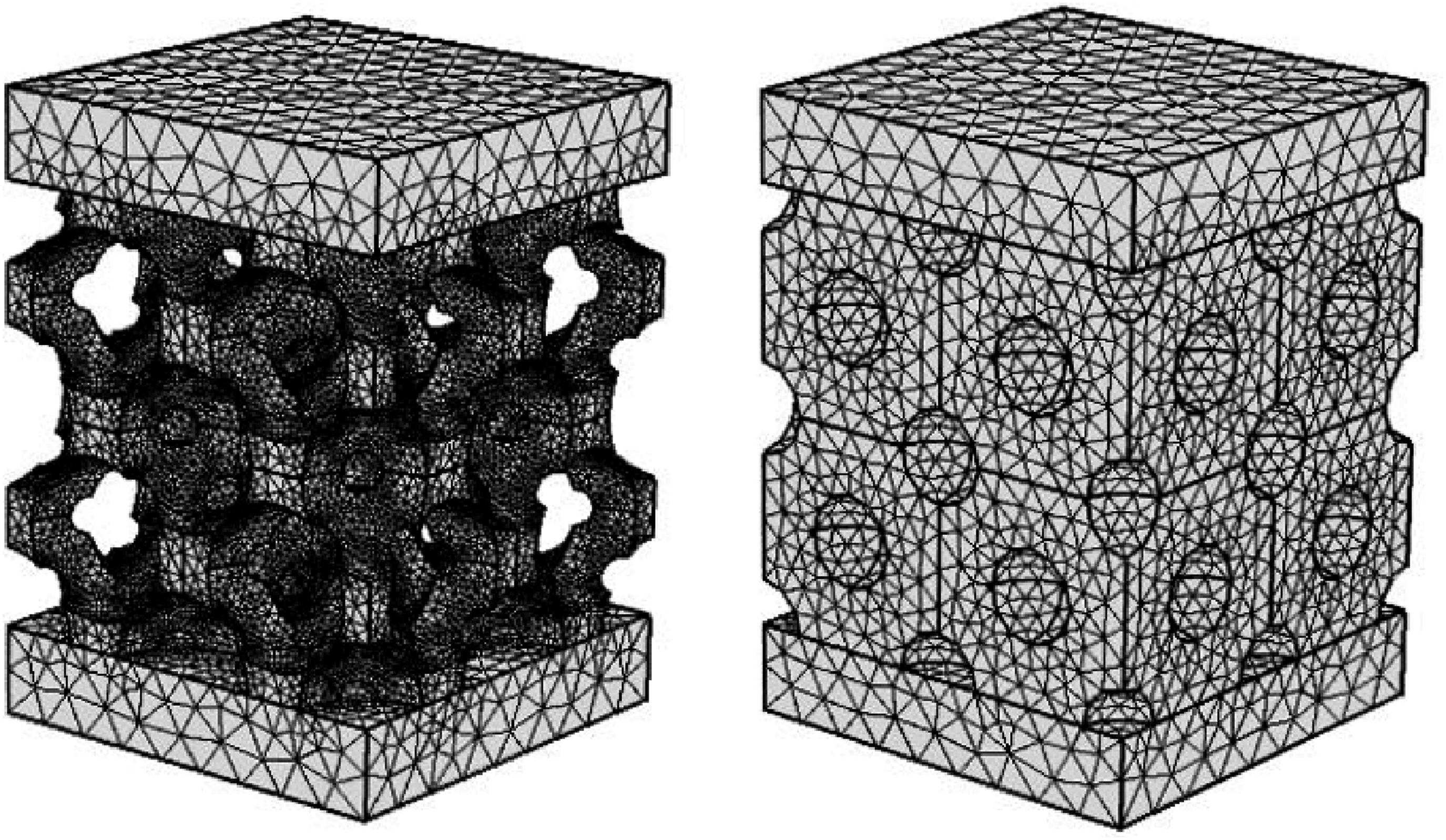
Young’s modulus of carbon foam structure can be determined using Hooke’s law for a one-dimensional stress scenario, as follows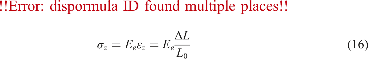
Here,
The Poisson’s ratio is similarly defined as,
Under the assumption of macroscopic isotropic elastic behavior, the effective Poisson’s ratio can be computed as,
The dimensionless effective young’s modulus for carbon foam is determined as;
The symbol
Result and discussion
FEA results
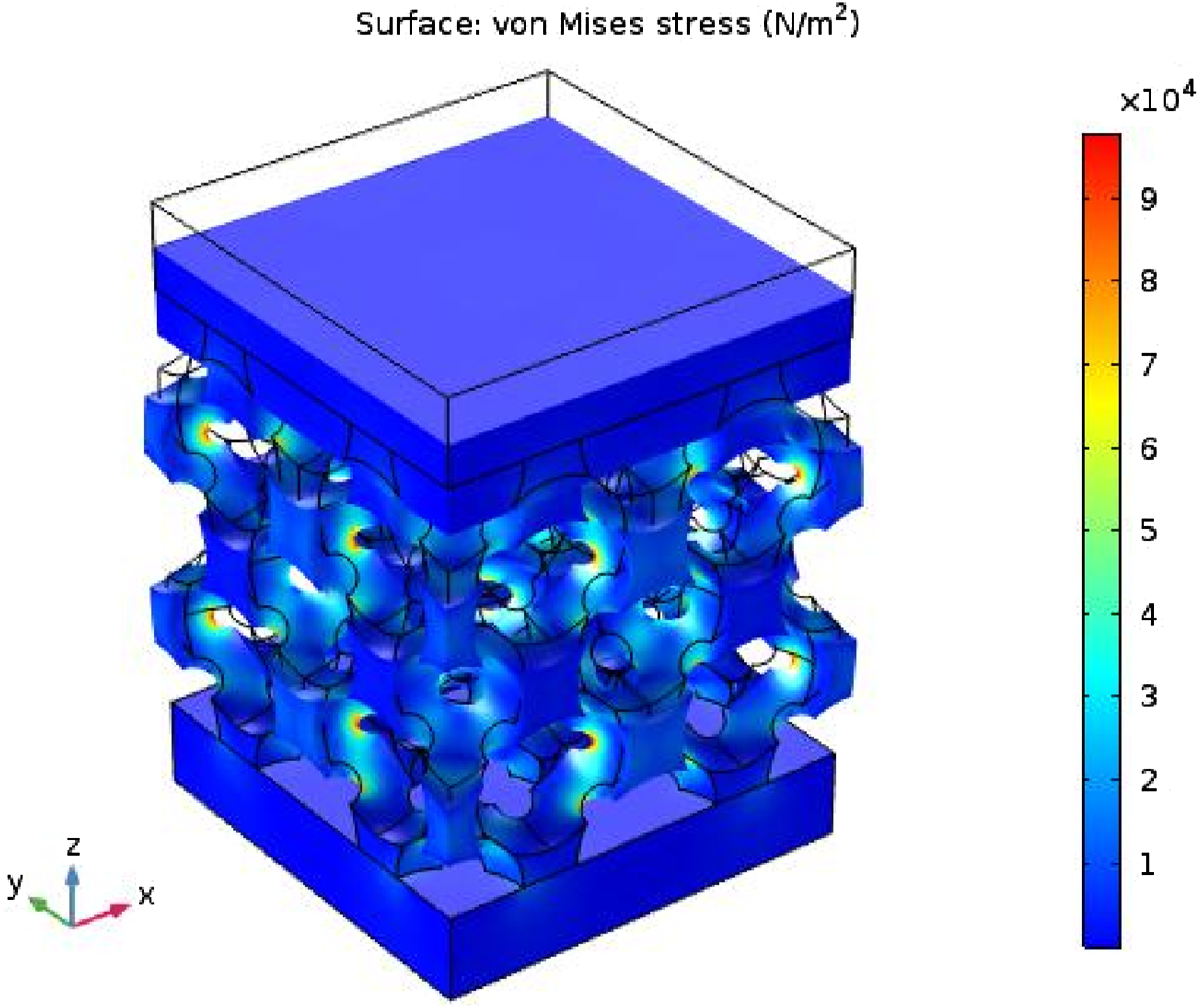
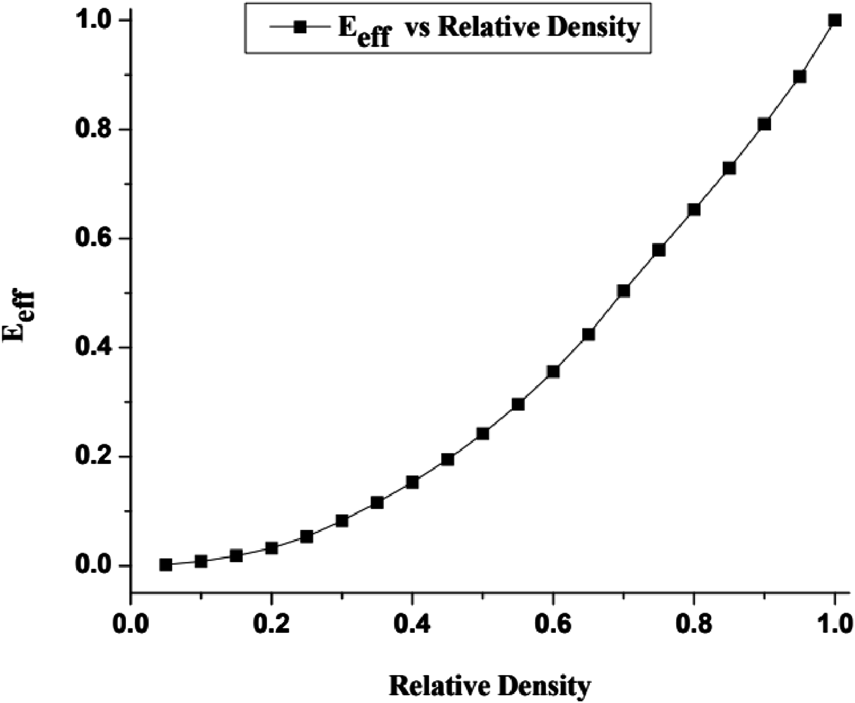
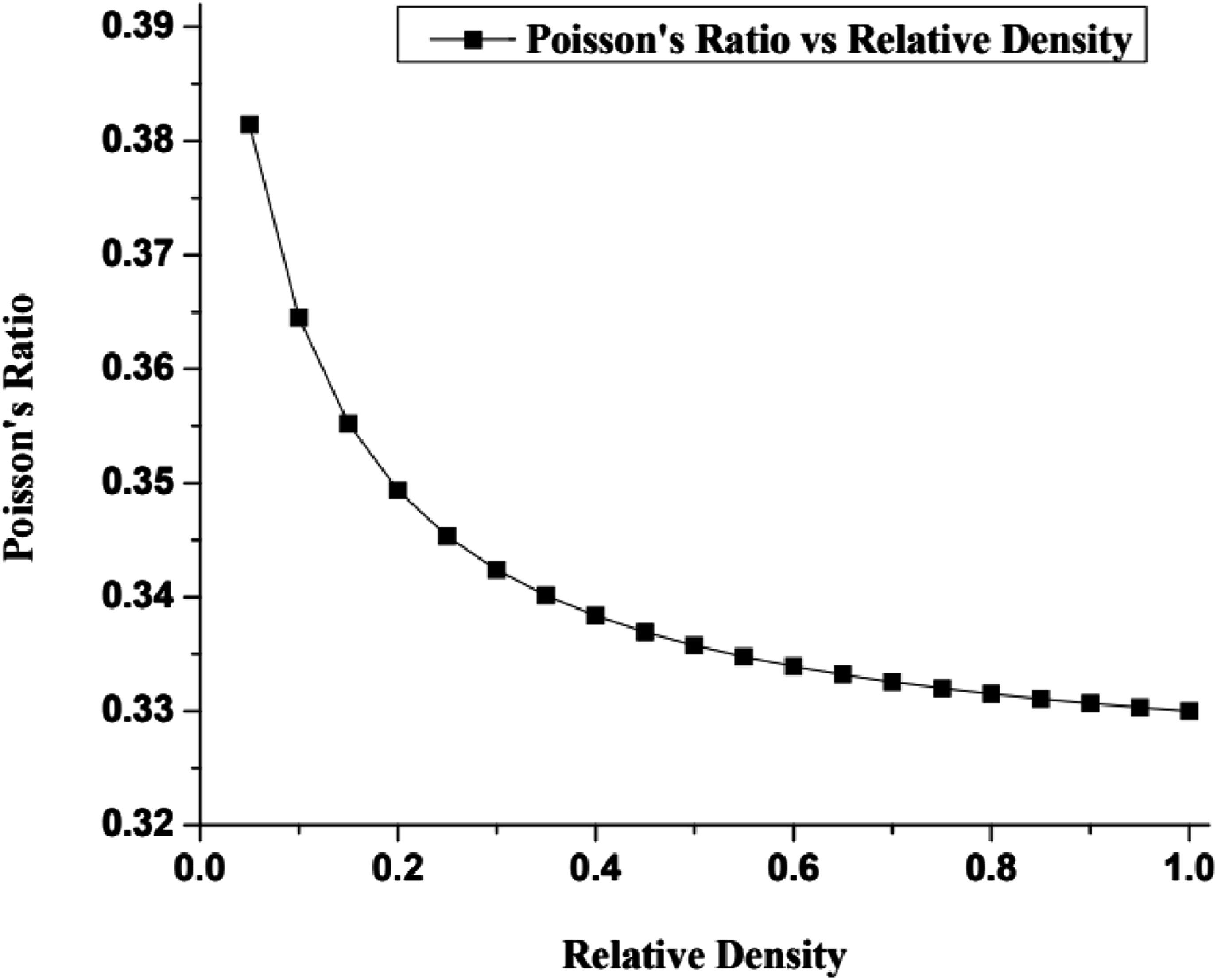
To showcase the practical use of the presently developed carbon foam model, a parametric study is being undertaken here on three-dimensional carbon foams. The motivation for this study emerges from the modeling of these foams. The symmetry and linearity of the carbon foam structure allow for the determination of its mechanical characteristics by analyzing the load-displacement relationship derived from the uniaxially loaded cells. The FE stress analysis is used to simulate the linearly elastic mechanical compressive testing of carbon foam models as depicted in Figures 10 and 11. The effective Young’s modulus for the full-ranges of relative density of foams is determined by FEA, and the corresponding results are depicted in Figure 12. In addition, the Poisson’s ratio for the full-ranges of relative density of foams is determined using FEA, and the results are presented in Figure 13. In the following sections, the results derived from the current model will be compared with those of existing open and closed-cell models found in the literature. FE stress analysis results of carbon foam (25% porosity) obtained from COMSOL Multiphysics. FE stress analysis results of carbon foam (85% porosity) obtained from COMSOL Multiphysics. Young’s modulus variation with relative density. Poisson’s ratio variation with relative density.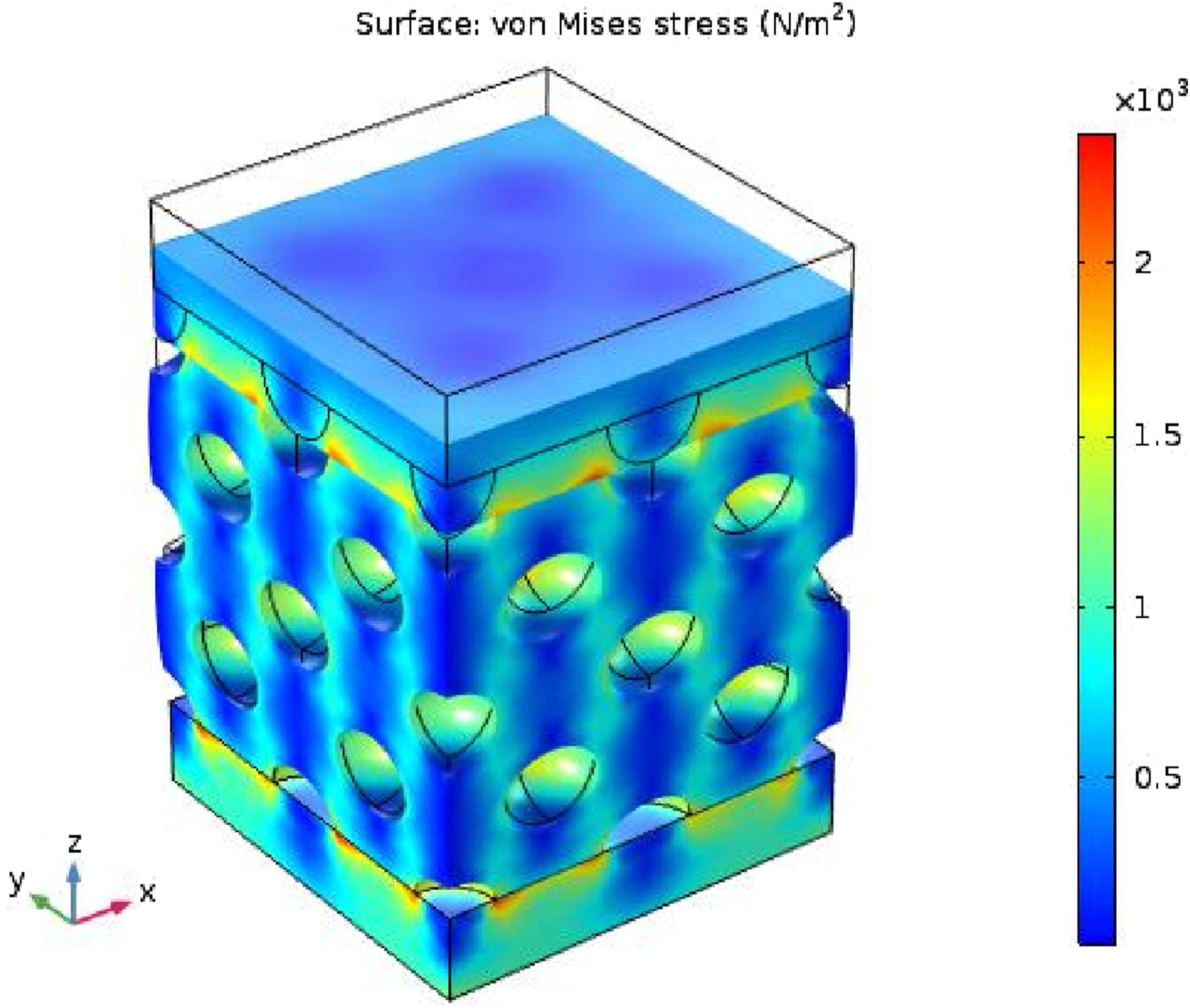
Present model versus low density (open-cell) foam models
In this study, a total of five open cell (low density) foam models were employed to validate the finite element method (FEM) results and to demonstrate the proposed model. One of the initial contributions in the field is the theoretical tetrahedral unit cell model proposed by Warren and Kraynik,
16
which is focused on the linear elastic properties of 3D open-cell foams. The elastic constants for homogeneous struts within a tetrahedral framework are calculated using the approach outlined herein, as follows;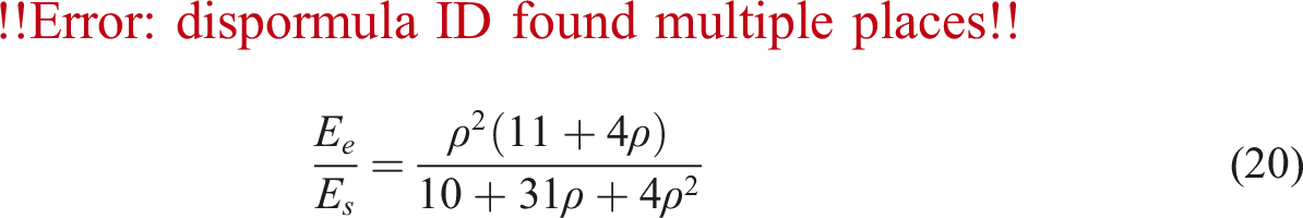
The succeeding model of open cell foam, proposed by Zhu et al.,
18
provides closed-form solutions for evaluating the elastic constants of foam structure composed of Kelvin cells, as outlined below:
The third strategy utilized as a comparative criterion is the utilization of 3-D Voronoi models that have been built by Gan et al.,
19
with the absence of defects. By utilizing three-dimensional random Voronoi cells, the mechanical properties of open cell foams that are linearly elastic were determined. The process involved conducting curve fitting to finite element method (FEM) data as;
The next approach is the semi-empirical formula recommended by Gibson and Ashby,
15
it reveals
Gibson and Ashby 15 assert that the constants ‘C' and ‘n' are contingent upon the microstructure of the solid material. The bulk and shear moduli demonstrate similar connections, potentially defined by different values of ‘C’ and ‘n’. The researchers maintained a consistent assumption of Poisson’s ratio (0.33) throughout their investigation.
The variable ‘n’ often resides within the range
For 
The last study by Roberts and Garboczi
21
examined the elastic characteristics of open-cell foams made of random Voronoi cells using a tessellation technique. The researchers used the formula 
The results produced from the current model have been compared with other open-cell foam models that possess varying porosity values in Figures 14–16. The effective Young’s modulus values derived by FEA on the current carbon foam model are highly consistent with the FEA results in Roberts and Garboczi
21
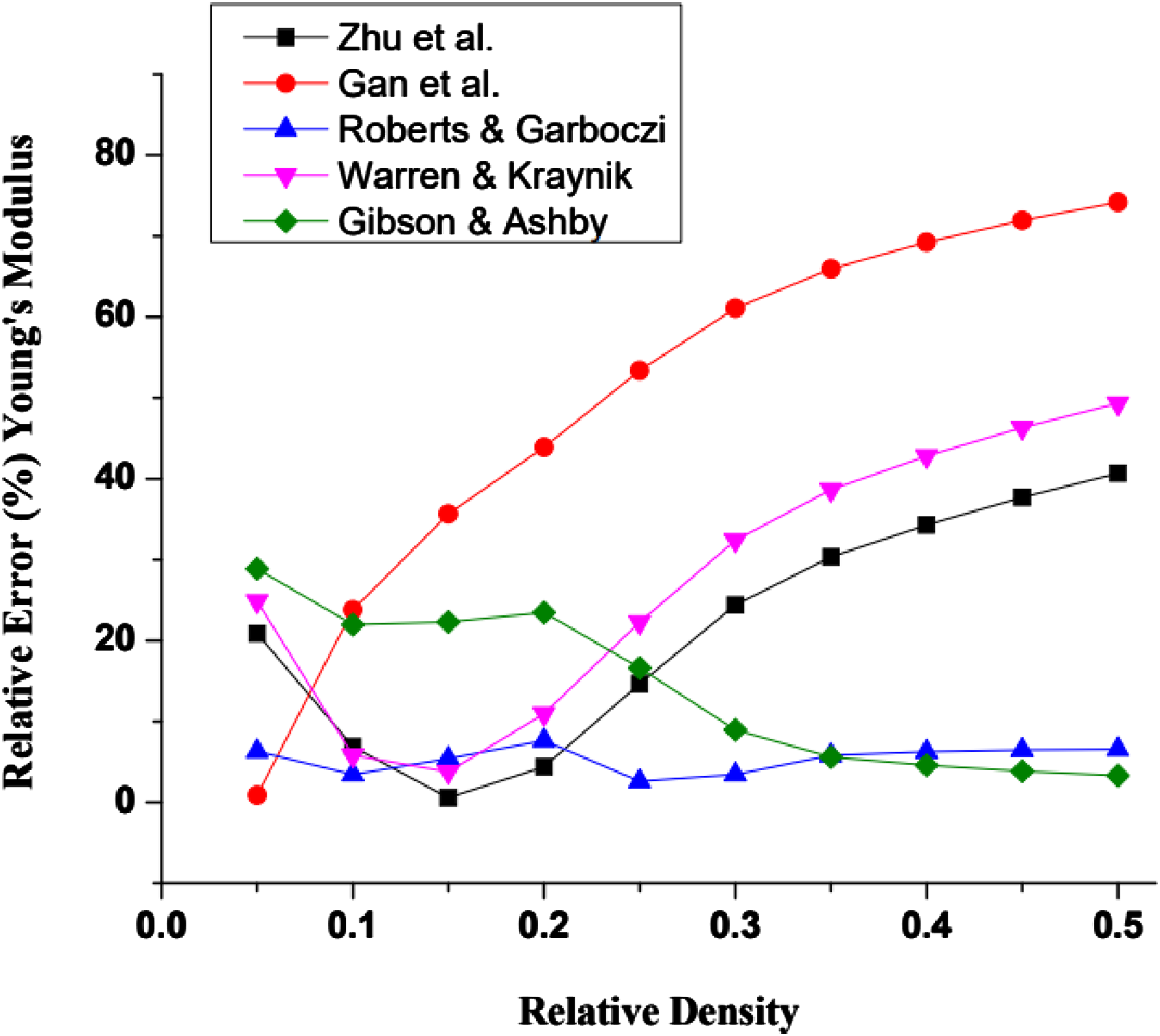
on a random Voronoi tessellation model. Moreover, the relative error related to Young’s modulus between the current model and other discussed models are presented in Figure 16. The findings indicate that the relative errors from the utilization of open cell foam models are negligible, particularly when considering low relative densities. In contrast to the formulation proposed by Gan et al.
19
and Warren-Kraynik,
16
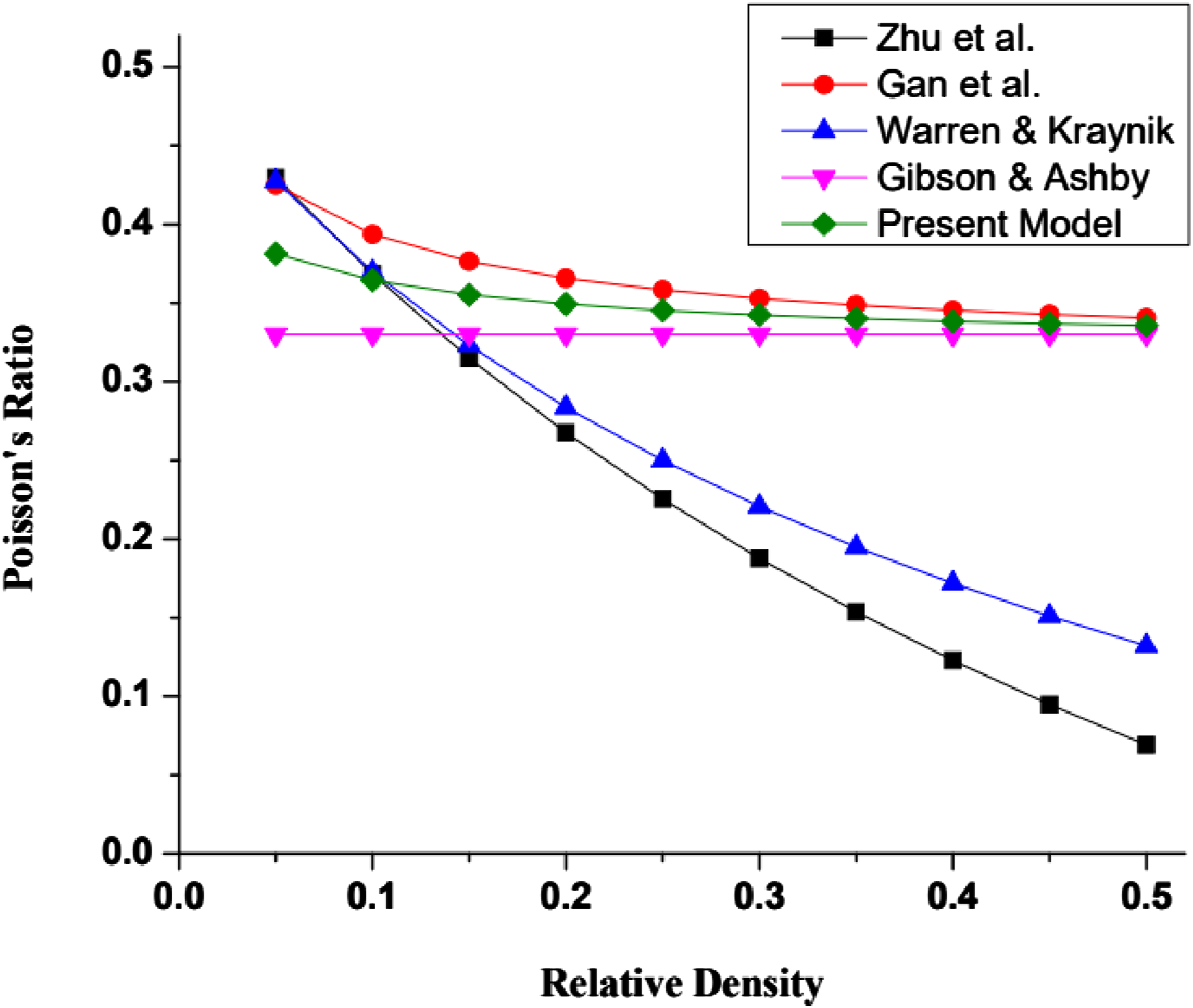
the comparative analysis reveals that the relative error between the current model and alternative models remains below 35%, particularly in relation to Young’s modulus. Furthermore, the Poisson’s ratio values derived by the present model lies between the results reported in Gibson and Ashby
15
and Gan et al.
19
Young’s modulus variation with relative density for open-cell foams. Poisson’s ratio variation with relative density for open-cell foams. Relative error variation with relative density for Young’s modulus in open-cell foams.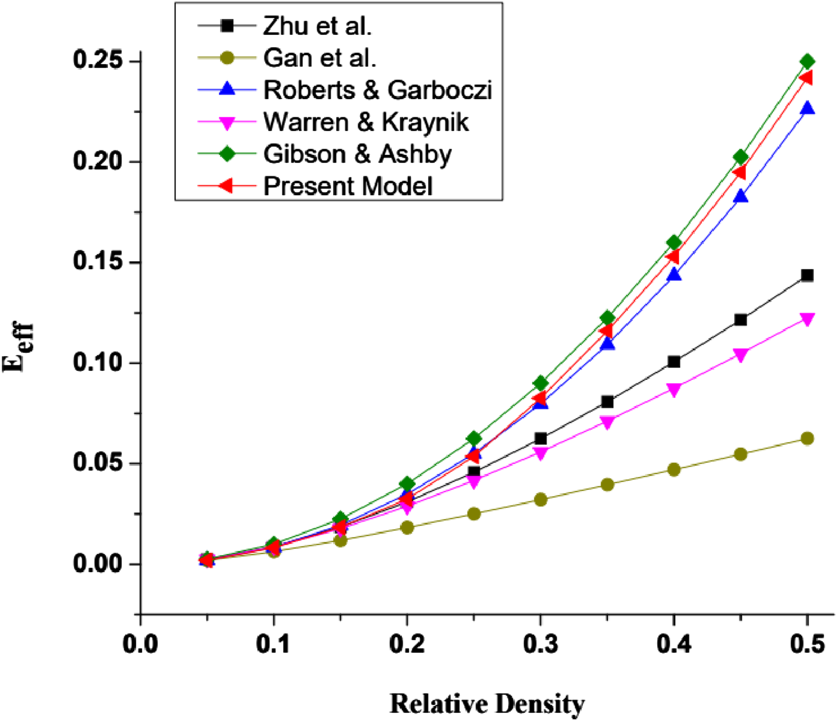
Present Model versus high density (closed-cell) foam models
Similarly, four closed-cell foam (low density) models were used to examine the FEA results and present model. The first model is Isotropic Flat Plate Model developed by Grenestedt
36
by considering isotropic nature of foams. The elastics constants are calculated based on the stiffness invariants and the beam theory as follows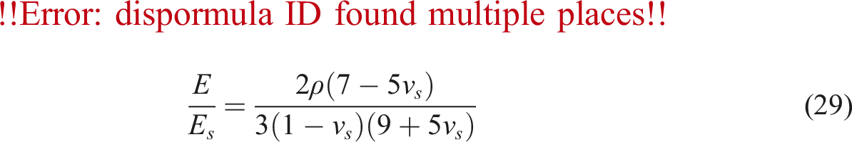

Another closed-cell model is based on the Composite Sphere Model developed by Ramakrishnan-Arunachalam.
37
This model reveals;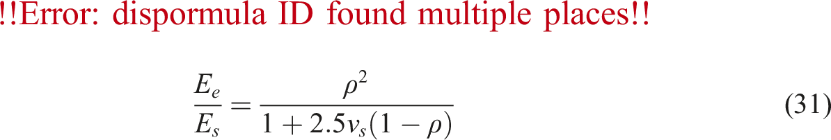

The third approach is the semi-empirical formula proposed by Gibson and Ashby
15

The variable
By putting 
The last model proposed by Roberts and Garboczi
22
utilized a tessellation technique to analyze the elastic characteristics of closed cell foams made of random Voronoi cells. The researchers examined a three- or four-parameter relationship in order to accurately depict the entire range of density. This was achieved by employing the following equation.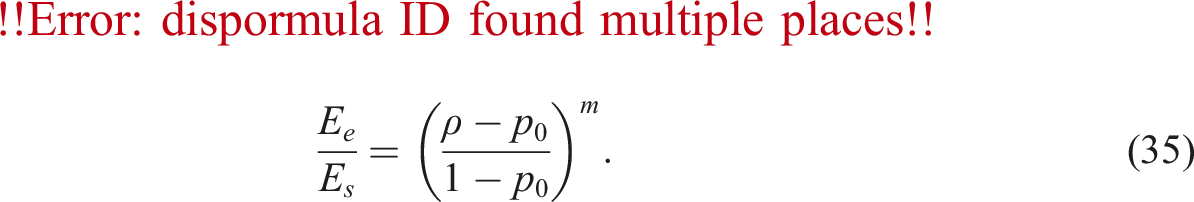
The values of the parameters ‘P
0
’ and ‘m’ for the full-density ranges (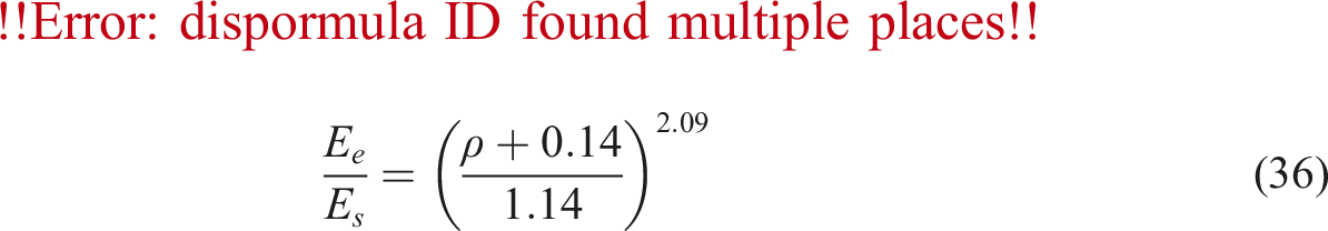
The results produced from the current model are compared with the four closed-cell foam models, which have varying porosity values, as shown in Figures 17–19. The effective Young’s modulus values derived by FEA on the current carbon foam model are highly consistent with the analytical results reported in Ramakrishnan-Arunachalam
37
and FEA results in Roberts and Garboczi.
22
Moreover, the relative error related to Young’s modulus between the current model and other discussed models are presented in Figure 19. Young’s modulus variation with relative density for closed-cell foams. Poisson’s ratio variation with relative density for closed-cell foams. Relative error variation with relative density for Young’s modulus in closed-cell foams.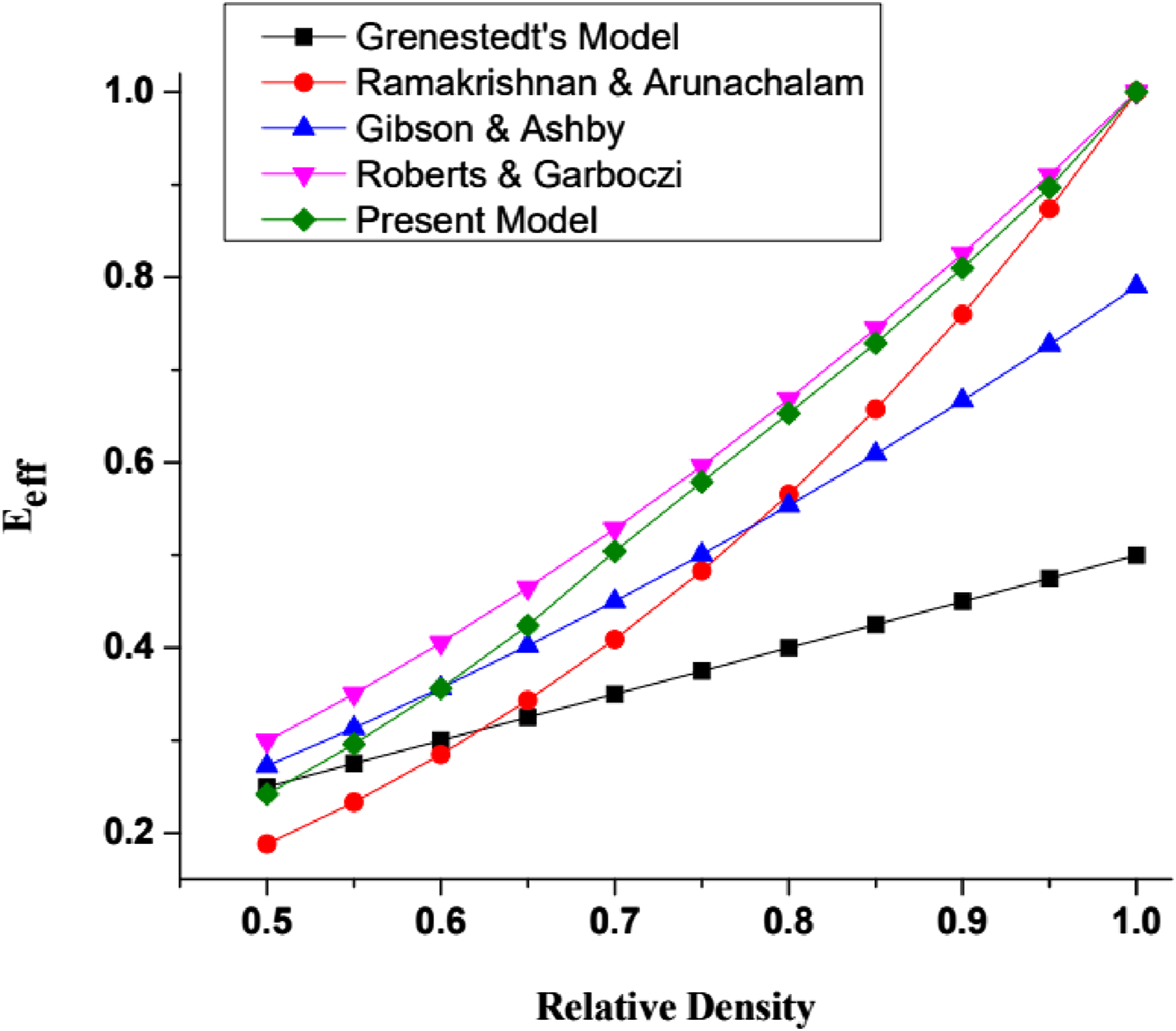
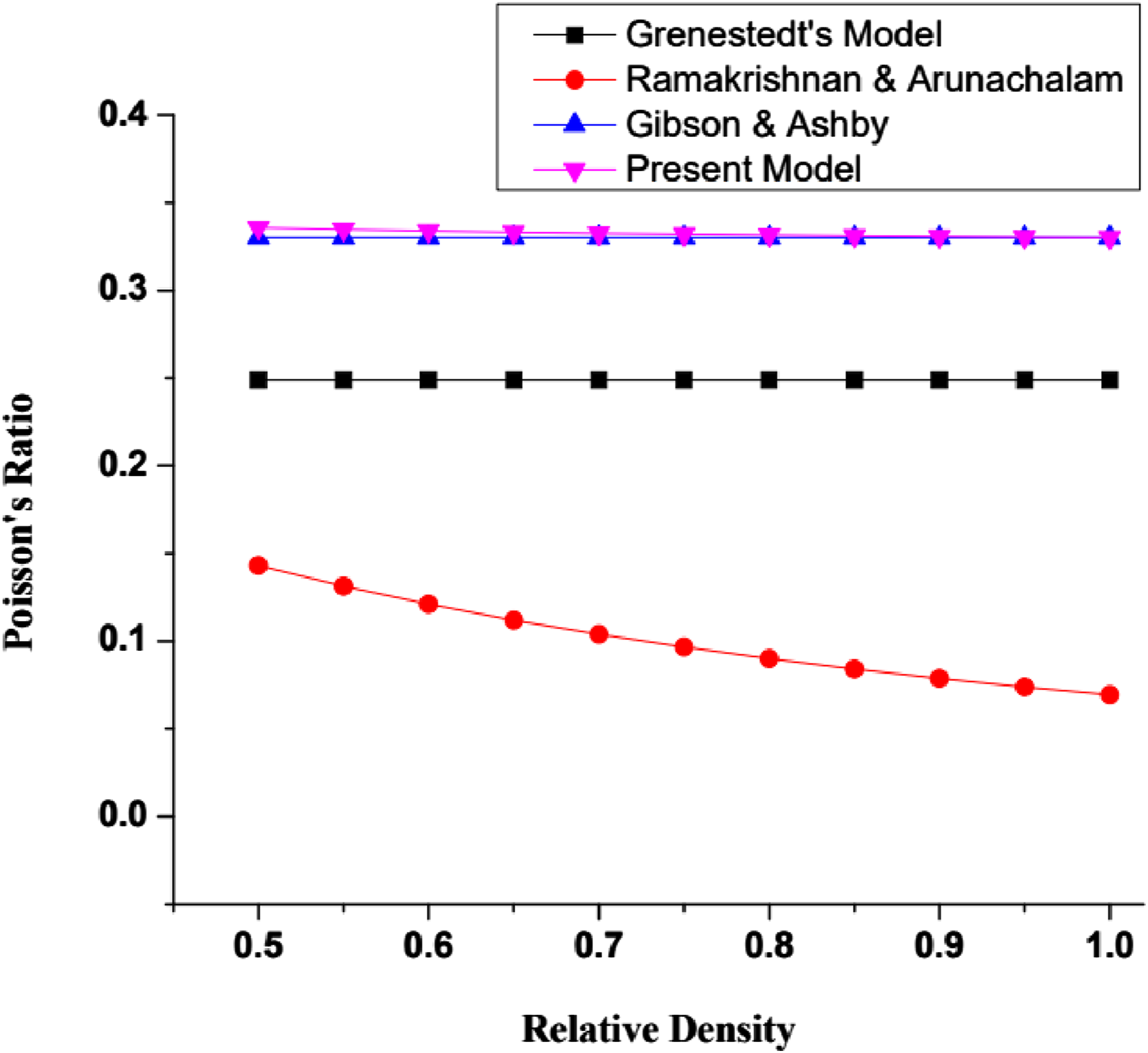
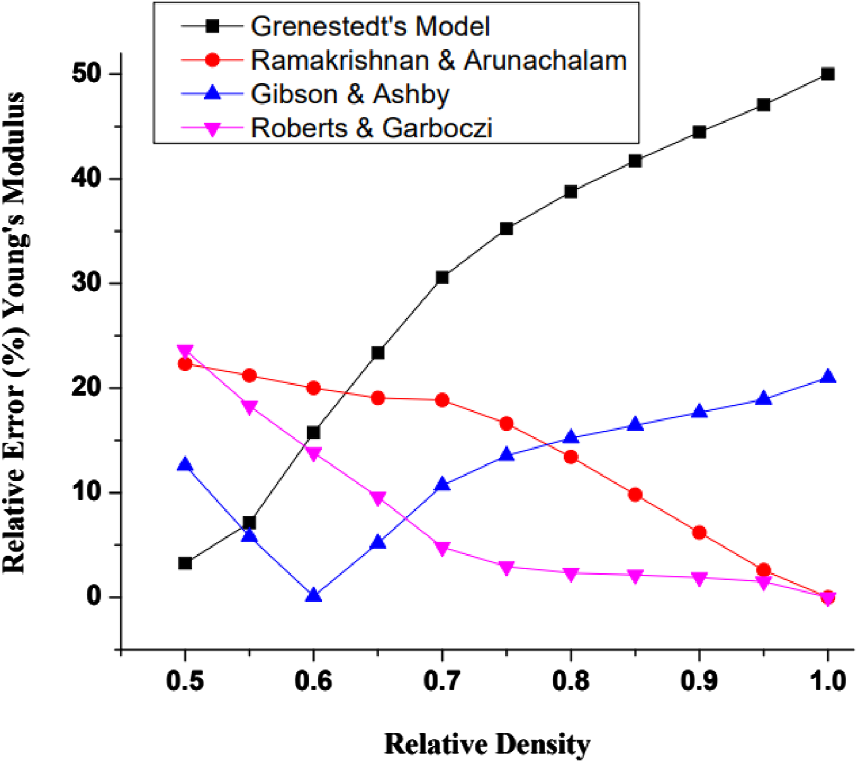
The findings indicate that the closed-cell foam models exhibit negligible relative errors, particularly when considering higher relative densities. In contrast to the formulation proposed by Grenestedt, 36 it is observed that the relative error between the current model and other models is consistently below 25%, particularly in relation to Young’s modulus. Furthermore, the Poisson’s ratio values derived by the present model lies close to the results reported Gibson and Ashby. 15
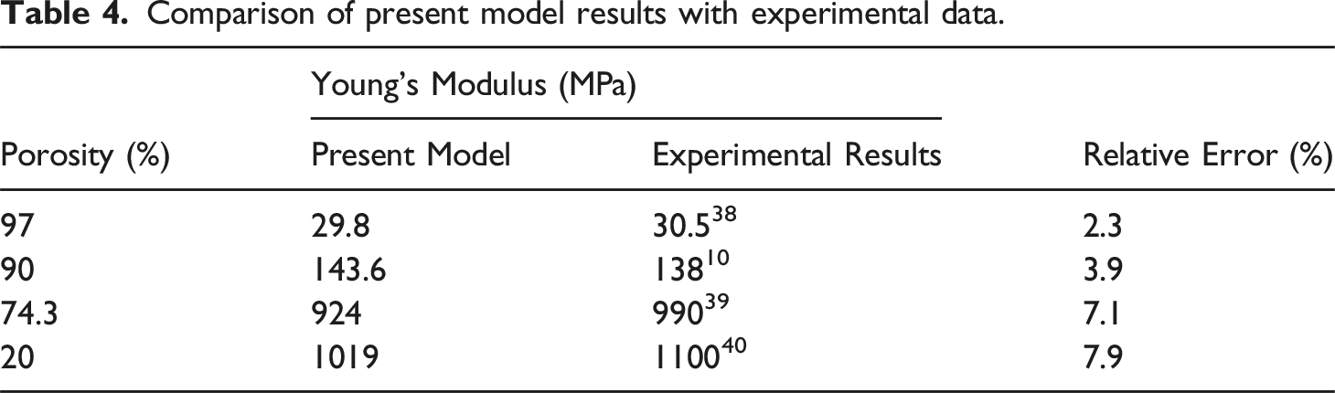
Present model versus experimental results
Comparison of present model results with experimental data.
Conclusion
Microscopic investigations of the carbon foam material led to the development of a unit cell model with a hybrid cubic (HBC) structure, combining features of both BCC and FCC arrangements. This model effectively explains the physical properties of various carbon foam structures, including closed, open, and mixed configurations. By adjusting the pore diameter, the foam structure transitions from a closed to an intermediate mixed structure and eventually to an open structure. Additionally, using a specific dimensional ratio (D) is a more effective approach than relying on pore diameter and unit cell length to represent the porosity and relative density of foam structures.
A parametric analysis was conducted to apply the novel model to carbon foams across a full range of relative densities. The predicted values of effective Young’s modulus and Poisson’s ratio closely align with those from other analytical models and experimental results for both low and high-density foams. The current model’s Finite Element Analysis (FEA) results for low-density carbon foams closely match those from Roberts and Garboczi’s random Voronoi tessellation model. 21 Poisson’s ratio values are in the same range as those reported by Gibson and Ashby 15 and Gan et al., 19 For carbon foams with a high density, the values of Young’s modulus agree with those from Ramakrishnan-Arunachalam 37 and Roberts and Garboczi, 22 and the values of Poisson’s ratio agree with those from Gibson and Ashby. 15 Also, the fact that our predictions match the AFRL experimental data shows that the present model can accurately simulate the material’s response under similar porosity conditions. This gives us confidence in its use for predicting the mechanical properties of porous carbon-based materials. This agreement also emphasizes the reliability of our approach for future studies and engineering applications involving carbon foams with varying structural characteristics. Additionally, the models can be expanded to study the mechanical properties of other 3D foam structures, like metal and ceramic foams.
Footnotes
Declaration of conflicting interests
The author(s) declared no potential conflicts of interest with respect to the research, authorship, and/ or publication of this article.
Funding
The author(s) received no financial support for the research, authorship, and/or publication of this article.