






Abstract
Foams are essential materials in engineering designs across the building and transport sectors, as they provide a unique combination of light weight, structural support, thermal and acoustic properties, and energy absorption. This study focuses on a rigid biofoam made from castor-oil polyurethane (PU) and examines its mechanical properties under compressive and three-point bending loads. No chemical additives are used except a castor-oil polyol, diisocyanate, and water. The elastic compressive modulus is evaluated for loads applied both parallel and perpendicular to the foam expansion direction, and results demonstrate that the foam is mildly anisotropic with an anisotropy shape index close to 1. A microtomographic scan analysis is conducted to investigate the internal structure of the foam. The elastic flexural modulus obtained is 9.2 ± 1.5 MPa. The compressive modulus (9.08 ± 0.71 MPa) and the elastic collapse stress (405 ± 29 kPa) are comparable to or higher than those reported for other rigid PU foams within the same density range in the literature. This finding indicates that a rigid biofoam can be successfully produced without the use of additives, such as catalysts and surfactants, while still exhibiting mechanical performance comparable to other rigid PU foams.
Introduction
Polyurethanes (PUs) are the only class of polymers that can exhibit thermoplastic, elastomeric, or thermoset behaviour, depending on their chemical structure and morphology. The material can be manufactured as foams, elastomers, or adhesives, depending on the specific requirements of each application. Owing to these unique properties, PUs are widely used across various sectors, including construction, furniture, paints, and the automotive industry.1,2
The fabrication of polyurethanes traditionally involves the use of petrochemical-derived polyols. However, growing concerns over environmental sustainability and the depletion of non-renewable resources have driven the search for more eco-friendly alternatives derived from soy, castor oil, sugar cane and palm.3–7
In this context, castor oil emerges as a promising raw material for polyurethane production. The castor-oil plant (Ricinus communis) is widely available in tropical and subtropical regions. Brazil is the third-largest producer of castor-oil seeds, behind only China and India. 8 Castor oil, extracted from the seeds of the castor-oil plant, is a natural polyol, presenting a high content of ricinolein (approximately 89%), a triglyceride of the ricinoleic acid, a fatty acid present in few vegetable oils, with a hydroxyl group at the 12th carbon of the molecule.8,9 Other vegetable oils, such as soy, palm, sunflower, and olive, can also be used for the synthesis of polyurethanes. However, such oils are edible, so castor oil does not compete with them in the food market. Moreover, other vegetable oils should necessarily undergo epoxidation or hydroxylation to create the necessary reactive sites.7,8 A renewable and biodegradable source, castor oil also offers the advantage of low toxicity, making it an attractive alternative to traditional petrochemical-based polyols.3,4,6,10 However, the commercial application of castor-oil-based PU is limited by the poor mechanical properties of the foam, attributed to factors such as low hydroxyl value, low reactivity of secondary hydroxyl groups, and steric hindrance. 10
Various chemical methods have been proposed to overcome the drawbacks of castor oil, such as epoxidation, transesterification, ozonolysis, and functionalization of the polyol chain, 11 as well as improved castor-oil polyols currently available on the market. Recent studies have shown that commercially available castor-oil polyols exhibit enhanced mechanical properties. Different suppliers apply distinct chemical modifications to the pristine castor oil, and comparing the physical and mechanical properties of castor-oil PU foams is thus challenging, as their characteristics are influenced by composition and the reagents used in the fabrication process. The studies below used polyols and diisocyanates from the same supplier, allowing a direct comparison of results.
Soares et al. 11 studied the effects of mixing different polyols on the physical and mechanical properties of rigid PU foams using a mixture-design approach. Samples were fabricated with two distinct castor-oil polyols (RD 70 B and AGT 1315 B) and one pre-polymer (diisocyanate with castor-oil additives, RD 70 A). Both polyols and the pre-polymer were gently donated by Imperveg (Brazil). While RD 70B is a polyol developed for the fabrication of rigid foams, AGT1315B was designed as a waterproof coating for water reservoirs and the construction sector. The polyols and the pre-polymer were mixed in varying proportions to produce three different closed-cell foams. The mass fractions of RD 70B, AGT 1315B, and RD 70A ranged from 20 to 40 wt%, 0 to 30 wt%, and 50 to 60 wt%, respectively. It is worth noting that the AGT1315 B component was not used as a full substitute for the RD 70B polyol; rather, it was intended to increase density and enhance the mechanical properties of the foams. However, the authors observed that weight fractions exceeding 30% of this component hindered the complete curing of the foams. The authors highlight the effect of the mixture proportion between components RD 70B and AGT 1315 B on the mechanical properties of the foams. The compressive elastic modulus and density ranged from 11 to 15 MPa and 61 to 100 kg/m3, respectively. The compressive strength ranged from 273 kPa to 430 kPa.
Lavazza et al. 12 investigated the morphology, thermal and mechanical properties of rigid, bio-based PU foams, fabricated with two distinct castor-oil polyols and one pre-polymer, the same used by Soares et al. These commercial components were mixed at varying proportions to obtain three different closed-cell foams. The compressive elastic modulus ranged from 8.52 to 13.32 MPa, and densities ranged from 80 kg/m3 to 140 kg/m3. The authors reported higher compressive elastic modulus and lower porosity for the formulation containing a higher mass fraction (30 wt%) of AGT1315 B, indicating a positive effect of this polyol on the mechanical properties of the investigated foams. The cellular morphology was also refined by AGT1315 B, with smaller pores and lower porosity, as observed by computed tomography.
Both studies used AGT1315 B as a secondary polyol to investigate its effects on the mechanical properties and morphology of the fabricated foams. This polyol, as previously mentioned, is a commercial polyol developed by Imperveg as a waterproof, non-foaming coating for water reservoirs and the construction sector. The present work focuses on creating new foam from this polyol alone, and the research demonstrates the feasibility of fabricating a rigid foam based on AGT 1315 using a very simple formulation and a straightforward fabrication process.
Even though the basic formulation of polyol, polyisocyanate, and a foaming agent is, in principle, sufficient to produce foams, most research reported in the literature uses catalysts and surfactants. Catalysts control and synchronize blowing and foam gelation, preventing defects and foam collapse during formation. 13 Eliminating catalysts, particularly those containing heavy metals or other hazardous substances, can lead to more environmentally friendly, safer production processes, which are particularly relevant to green synthesis methods and the development of sustainable materials. 14 Yang et al. 15 reported the successful fabrication and characterization of a catalyst-free, water-blown rigid PU foam, produced with bio polyols synthesized with 1, 6 hexanediol, malic acid and citric acid. Closed-cell rigid foams were made, with compressive strength and density values in the ranges of 191–238 kPa and 42.6–51.4 kg/m3, respectively. It is worth noting that, however, a silicone surfactant was used. Chen et al. 16 investigated biobased, catalyst-free, non-isocyanate polythiourethane foams using acetone or ethyl acetate as physical blowing agents. The compressive elastic modulus achieved 30-203 kPa, at a density of 140–300 kg/m3.
The use of surfactants is more critical. Surfactants, particularly silicone-based ones, reduce the surface tension at the polymer-gas interface during foam blowing. This reduction in surface tension is considered essential for stabilizing the foam structure and preventing bubble coalescence, thereby maintaining a uniform cell-size distribution. The presence of surfactants affects the openness and firmness of the foam cells.13,16,17 In the absence of surfactants, a foaming system is prone to catastrophic coalescence and eventually foam collapse. 18
Surfactant-free porous materials can be engineered using particle-stabilized interfaces, often referred to as the Pickering mechanism. While defined initially for emulsions—where liquid droplets of a disperse phase (e.g., oil) are stabilized in a continuous phase (e.g., water) by colloidal solid particles substituting traditional surfactants—this principle is equally applicable to foams. 19 In this context, colloidal solid particles adsorb at the gas-liquid interface, replacing conventional molecular surfactants to stabilize the cellular structure against coalescence. For instance, Huang et al. 20 used oxidized nanocellulose and carboxymethyl chitosan as a Pickering emulsion to obtain phase-change foams of encapsulated beeswax for thermal insulation. Similarly, Huynh et al. 21 fabricated a flexible PU foam with gold nanoparticles as an antibacterial dressing. This foam was stabilized via a Pickering mechanism mediated by gold nanoparticles, using a mixture of poly(dimethylsiloxane) and hexamethyldisiloxane acting as a surface modifier to tune the particles’ wettability at the gas-liquid interface. Finally, hydrophobic silica particles with a diameter of 50–70 nm were also used in a Pickering emulsion to stabilize polystyrene aerogel foams. 22
Silica foams were also fabricated using alternative surfactant-free methods. Huber et al. 23 synthesized flexible silica foams using a surfactant-free, sol-gel process based on dimethyldiethoxysilane and tetraethoxysilane in a water-ethanol co-solvent system. Uniaxial compressive tests revealed that the fabricated foams exhibit a compressive strength of up to 2.5 kPa. Ultralight silica foams (10–33 kg/m3) were also manufactured using a surfactant-free, high internal phase emulsion process, in which a hydrophobic silica precursor polymer is used to stabilize water-in-oil phase emulsions. 24
In any case, the surfactant-free approach is generally achieved using more sophisticated chemical formulations and fabrication protocols. In this work, however, no catalysts or surfactants are used (nor any substitutes); a stable architecture is achieved through a simple fabrication process for a PU system originally conceived as a waterproof coating (AGT 1315).
The fabricated foam provides a uniaxial compressive elastic modulus (9.08 MPa) and a collapse stress (405 kPa) as high as those offered by the foams investigated by Soares et al. 11 and Lavazza et al., 12 at the same density range (128 kg/m3). Rigid foams are promising for thermal and sound insulation, load-bearing structures for roofs and walls in the building industry, and impact energy absorption and structural reinforcement in the automotive industry.13,25,26
Materials and methods
Materials
The bicomponent PU system AGT 1315 is supplied by Imperveg® (Brazil). This PU system is composed of (1) a castor-oil polyol (AGT 1315 B) with a molecular mass of 930 g/mol, a hydroxyl value of 160 mg KOH/g, a functionality of 2.7; (2) a pre-polymer (AGT 1315 A) consisting of a polymeric methylene diphenyl diisocyanate (pMDI) with castor-oil additives, with a molecular mass of 250 g/mol and functionality 2. Distilled water is used as a foaming agent.
Fabrication
Solid PU
The physical and mechanical properties of foam are directly related to the elastic modulus and density of the solid material from which it is made. Moreover, the single most important characteristic of a foam is its relative density, i.e., the ratio between the bulk density of the foam and the solid material from which it is made. 25 Therefore, the compressive elastic modulus and bulk density of the solid PU fabricated with AGT 1315 are obtained. Such parameters are used in theoretical calculations and are also compared to those reported for other foams in the discussion of results. The bulk density is also used to determine the relative density of the fabricated foams.
The foaming agent (distilled water) is not used for this purpose. Samples are carefully manufactured to prevent the formation of entrapped voids in the material. It is assumed that the mechanical characteristics of the cell wall material are the same as those determined by testing the base polymer, as considered by Andersons et al. 27
The polyol and diisocyanate components are manually mixed for approximately 3 min to achieve homogeneity. The mixing is gentle to minimize bubble formation. The resulting polyurethane was then poured into a silicone mould and cured for 2 weeks in a controlled environment (22°C, 55% relative humidity), in accordance with the manufacturer’s recommendations.
PU foams
Foam formulation.
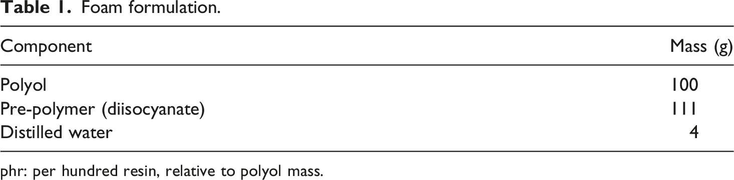
phr: per hundred resin, relative to polyol mass.
The fabrication process is straightforward. Initially, the polyol and distilled water are manually mixed for approximately 5 minutes until a homogeneous mixture is obtained. The pre-polymer is then added, and the solution is stirred manually for additional 5 minutes until it is fully uniform.
The mixture is then poured into an open MDF mould (250 × 250 × 100 mm3) covered with masking tape, allowing free expansion in the vertical direction. The foam is kept in the mold for 24 h and subsequently demoulded. Samples are cured for 2 weeks at 22°C and 55% relative humidity, according to the PU manufacturer. After curing, samples are cut on a bandsaw cutting machine and tested. A sample is shown in Figure 1. No catalyst is used in the fabrication process. The cream time of the fabricated foams is 15–20 min, while the tack-dry time is approximately 2 h. To ensure statistical reliability, five samples were manufactured in triplicate for both compression and three-point bending assessments. Rigid castor-oil PU foam sample.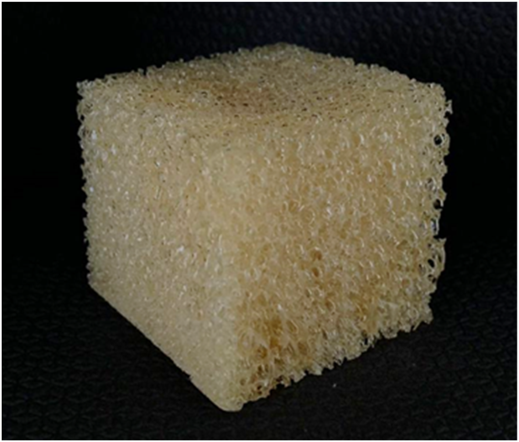
Characterisation
Solid PU samples
Bulk density
Bulk density is calculated as the ratio of dry mass to volume. Mass was recorded using a precision scale (±0.001 g), while dimensions were measured with a digital calliper (±0.01 mm). For each cylindrical sample, the volume is determined by averaging three separate measurements of both diameter and height.
Compressive test
Solid PU samples are tested under compression on an Instron 23100 universal testing machine equipped with a 50 kN load cell at a crosshead speed of 1.3 mm/min, according to ASTM D695-15. 28 Five cylindrical samples are tested, measuring 50 mm × 20 mm in height and diameter, respectively. The deformation of the samples is measured by the crosshead displacement of the machine. The slope of the initial linear portion of the stress-strain curve yields the elastic modulus.
PU foams
Bulk density
The bulk density is determined by the ratio of the dry mass to the volume of each foam sample before mechanical tests are performed, measured using a precision scale (±0.001 g) and a digital calliper (±0.001 mm).
Compressive test
Samples are tested on an Instron 23100 universal testing machine. Compressive testing is performed with the load applied along and perpendicular to the foam expansion direction to assess its anisotropic behaviour. Prismatic samples (51 × 51 × 30 mm3) are tested under compression using a 50 kN load cell at a crosshead speed of 3 mm/min. The geometry and size of the samples, as well as the test speed, follow the ASTM D1621-16 standard. 29 The slope of the initial linear portion of the stress-strain curve yields the elastic modulus. The elastic collapse stress is determined by the stress level at the end of the linear elastic region, i.e., at the onset of the plateau on the stress-strain compression curve.
Three-point bending test
Samples measuring 30 × 230 × 15 mm3 are also tested under three-point bending at a crosshead speed of 20 mm/min and a span of 180 mm, following ISO 1209-2. 30 Three replicates of at least five samples are manufactured for each test. Due to limitations of the mold size, flexural tests are performed only on samples whose length is perpendicular to the foam expansion direction.
Cell morphology
The morphology of the fabricated foam is analysed using optical microscopy (Jiusion portable digital USB) and an X-ray Bruker SkyScan 1172 microtomograph (Bruker, Belgium). The sample images are reconstructed using the SkyScan analysis software.
Outliers test
In order to select the samples for each replicate, all fabricated samples are subjected to the Weisberg t-test for outliers. The test is indicated to check data consistency for small sample groups.
31
The Weisberg t-test is essentially a Student’s t-test. Initially, a suspected outlier value, much higher or much lower than the others, is selected. The test is performed for each suspect value in turn. The mean and standard deviation are then calculated without the suspected outlier, so that the statistic is not biased in the direction of the outlier. The calculated statistical parameter (tcalc) is the difference between the outlier and the mean, measured as a fraction of the standard deviation of the samples (Equation (1)):
Results and discussion
Solid material
Figure 2 shows the stress–strain curves obtained from compression tests on cylindrical PU samples in the solid state, and the corresponding results are summarized in Table 2. The samples exhibit low variability, with coefficients of variation of 1.4% for density and 5.9% for elastic modulus, indicating consistency in both the manufacturing process and the storage conditions adopted. This low variability also contributes to reducing uncertainty in the theoretical characterisation of the material. The mean compressive elastic modulus obtained is 574 ± 34 MPa, and the mean bulk density of the solid material is 1057 ± 15 kg/m3. These values are used to determine the volumetric fraction of material in the edges of the foam. They are also compared to those reported for other foams in the discussion of results. These parameters are used to predict the mechanical behaviour of the fabricated foam using the Gibson-Ashby model for closed-cell foams. The bulk density is also used to determine the relative density of the fabricated foams. Mechanical behaviour of solid castor-oil PU samples under compression. Mechanical and physical properties of samples under compression. Pa: Parallel; Pe: Perpendicular; NA: Not Available.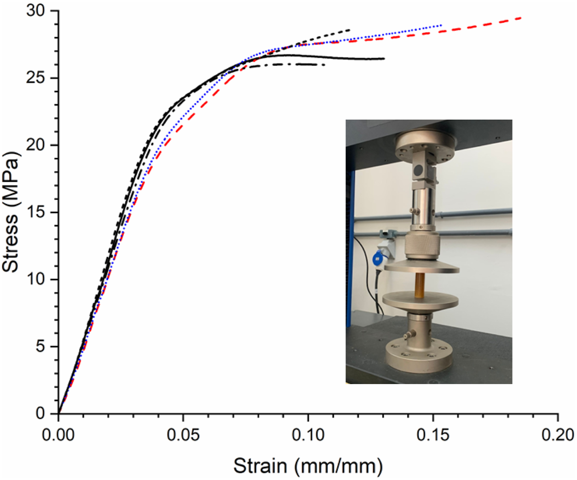
Polyurethane foam
Bulk density
Bulk density is determined for all specimens across both compression and three-point bending tests. These values are presented and discussed alongside the mechanical properties in the subsequent sections.
Bulk density and mechanical properties under compression
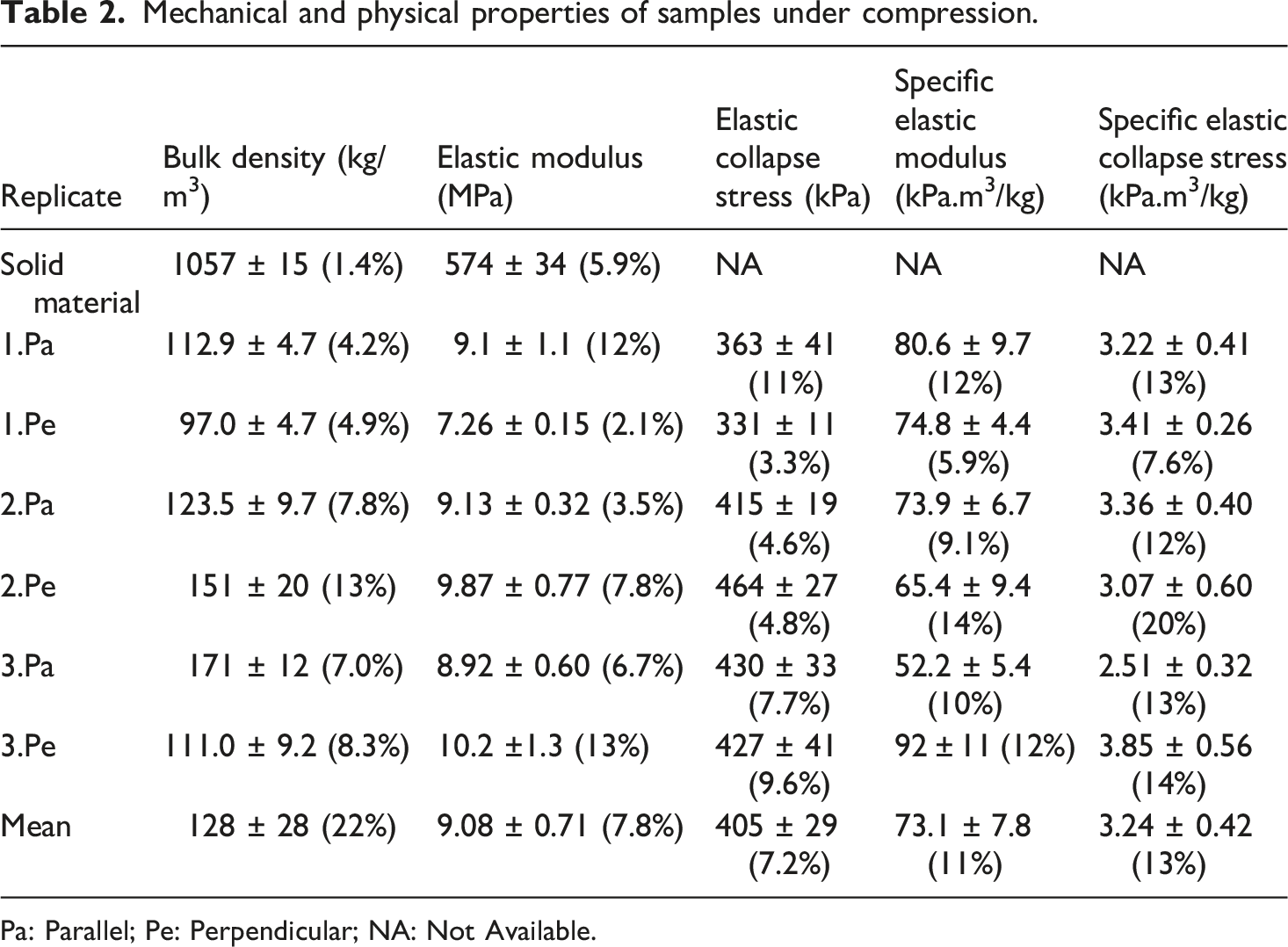
The mean values of compressive mechanical properties obtained in the parallel (Pa) and perpendicular (Pe) directions relative to the foam expansion are presented in Table 2, along with their respective standard deviation and coefficient of variation (in parentheses). The bulk density is also given, for which “Pa” and “Pe” mean only that the bulk density is obtained from samples tested in that particular load direction. The foaming process of the solid material (bulk density of 1057 ± 15 kg/m3) generates a porous structure with a mean bulk density of 128 ± 28 kg/m3 (Table 2), corresponding to a density reduction (porosity) of 87.9%. The expansion rate of the fabricated samples was determined to be 8.8, based on bulk density. The differences observed in bulk density are inherent to the manual fabrication process. Improvements on the fabrication process are currently being implemented to reduce these differences. Six or more samples were tested for each replicate, for compressive and flexural tests.
Despite a slightly higher elastic modulus in the direction parallel to foam expansion relative to the perpendicular direction, the anisotropy is small, as discussed below. The elastic collapse stress is approximately the same in both directions, corroborating Gibson and Ashby, who state that the effect of shape anisotropy on the collapse stress is weak.
25
The theoretical stress-strain curve for the fabricated foam, obtained from the Gibson-Ashby model (discussed below), is also presented along with typical experimental stress-strain curves for comparison (Figure 3). Three samples were tested up to densification (0.8 – 0.9 mm/mm strain). These samples are shown in blue in the larger graph. The inset presents the compressive behaviour at smaller strains (up to 0.14 mm/mm), obtained from these samples, as well as from all (seven) samples from replicate 1.Pa. The behaviour of other samples and replicates is similar. Seven to 14 samples are tested for compression (and three-point bending), for each load direction and replicate. After removing the outliers, 6 to 11 samples remain for each replicate. Since the anisotropy index obtained from microtomography is close to one (considering error bars), the foam can be regarded as isotropic, and the mean values of elastic modulus and collapse stress are obtained considering the values obtained in the parallel and perpendicular directions. Mechanical behaviour of foams under compressive load (parallel to the foam expansion direction; samples from replicate 1.Pa).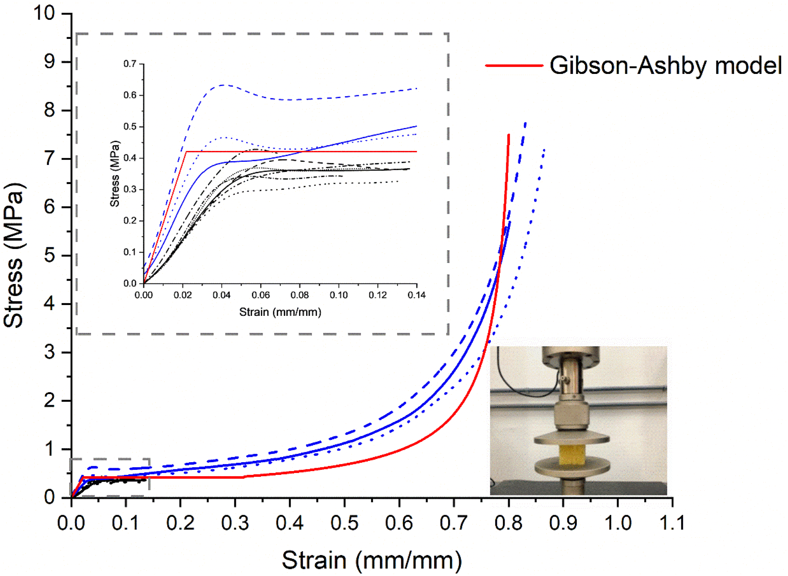
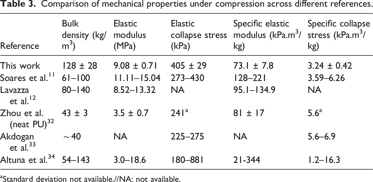
Comparison of mechanical properties under compression across different references.
aStandard deviation not available.//NA: not available.
Even though the bulk density of the fabricated foam is three times that reported by Zhou et al., 32 the elastic modulus is also approximately three times that reported by these authors. The specific elastic modulus is therefore statistically equivalent within error bars, as shown in Table 3. This implies essentially that the mechanical efficiency relative to weight is equivalent for both foams. In contrast, the specific elastic collapse stress is 42% lower, despite the 68% increase in the elastic collapse stress.
The mechanical performance of the fabricated foam is also comparable to that of other vegetable-oil-based PU foams. Akdogan et al. 33 investigated the effects of turkey-feather fibres on the thermal and mechanical properties of rigid PU foams based on used palm oil. Feather fibres provided higher compressive strength (285 kPa) compared to the foam made with a commercial, petroleum-based polyol GL-400 (246 kPa). The authors also assess the compressive strength of palm-oil-based PU foams without feather-fibre reinforcement (225–275 kPa). The bulk density of all investigated foams was around 40 kg/m3, with a closed-cell content around 51.6–84.9%. It is worth noting that the authors report compressive strength at 10% deformation, not the collapse stress; these parameters, even though not equivalent, are comparable. Despite the lower compressive stress obtained relative to the foams fabricated in this study, the lower density yields a higher specific compressive stress, similar to the value reported by Zhou et al. 32
Altuna et al. 34 characterized the physical and mechanical properties of rigid soybean-oil-based PU foams. Glycerol (20 and 30 wt% relative to the total polyol mass) was used as a crosslinker to enhance stability and improve the stiffness of the fabricated foams. The elastic modulus and collapse stress ranged between 3.0 and 18.6 MPa and 180 kPa–881 kPa, respectively, with a density of 54–143 kg/m3. The reported elastic modulus and collapse stress are comparable to those of the castor-oil PU foams investigated in this study within the same density range. It is worth noting that the mechanical properties of foams depend mainly on the elastic modulus of the solid material from which it is made, on the foam relative density, the volume fraction of solid material contained in the edges, as well as the shape anisotropy. These parameters are certainly different among the foams compared in Table 3. However, the intent is to compare the physical and mechanical properties obtained for the fabricated biofoam to other foams available in the literature fabricated with PU derived from different vegetable oils and show that the fabricated foam presents similar, competitive properties.
Bulk density and three-point bending test
Although the available literature focuses on the compressive behaviour of cellular solids, investigating their flexural response is critical for the design of foam-core sandwich structures, where the core is subjected to complex shear and bending moments. The flexural behaviour of foams reflects the complex interplay between cell-wall bending (elastic regime) and localized cell-edge buckling in the compression zone (onset of elastic collapse).
25
Figure 4 shows the three-point bending curves for samples whose length is in the direction perpendicular to the foam expansion, i.e., the direction of the applied load is parallel to the foam expansion. Table 4 shows the bulk density and the absolute and specific flexural moduli of the tested samples. The coefficient of variation is shown in parentheses. Mechanical behaviour of foams under three-point bending. Mechanical and physical properties for samples under three-point bending.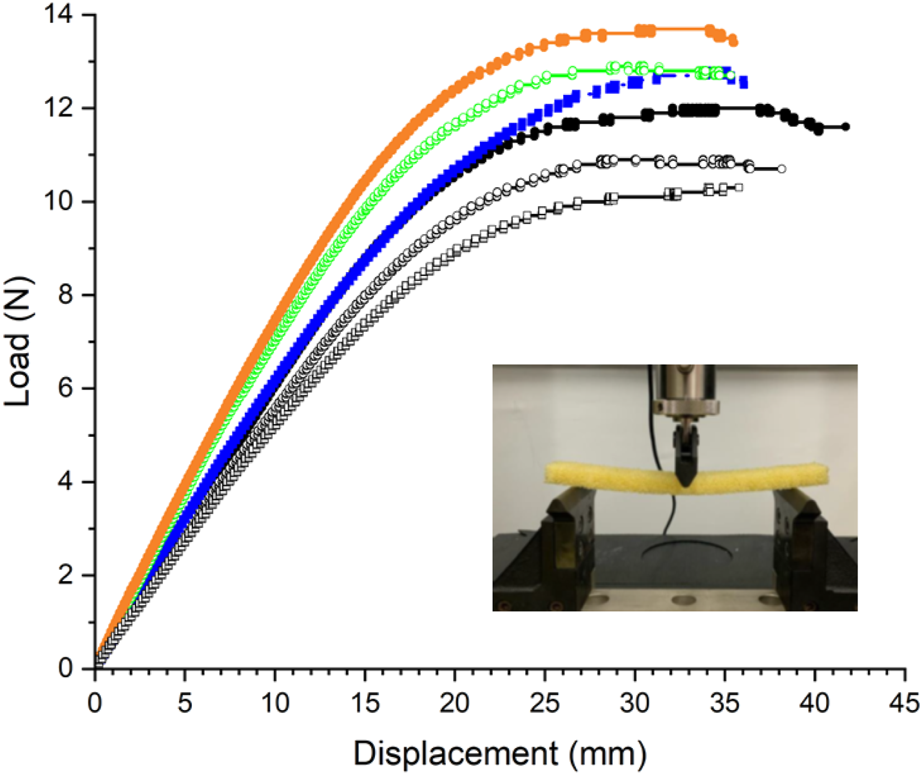
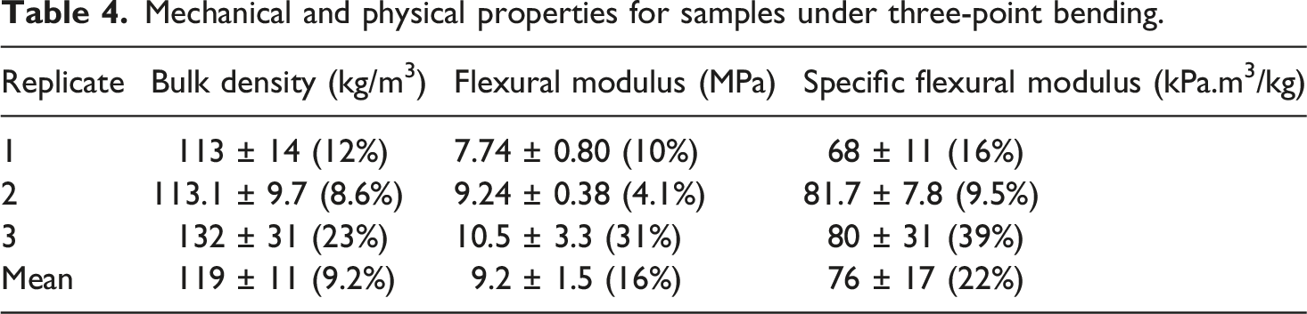
The mean flexural modulus of the fabricated foams with neat PU is comparable to other rigid PU foams, such as Zhou et al.
32
It is worth noting that this value corresponds to that reported by these authors for foams reinforced with carrot cellulose nanofibers (
Optical microscopy and microtomographic analyses
The morphology of the fabricated foam is analysed using both optical microscopy (Figure 5) and X-ray microtomography (Figure 6). Microscopic images reveal approximately spherical cells measuring 1 mm in diameter, forming a structure with apparently both open and closed cells (Figure 5(a) and (b)). Cells are slightly elongated along the foam expansion direction (Figure 5(c)). Faces of apparently closed cells are indicated by arrows in Figure 5(d). The cross section for these images is made on a plane perpendicular to the direction of expansion, except for Figure 5(c), in which the cross-section plane contains the direction of foam expansion. These images refer to samples from replicate 1.Pa. Other samples and replicates display a similar morphology. Optical microscopy images of foam samples. (a): 23× magnification; (b): 53× magnification. (c): plane containing the foam expansion direction showing the slight shape anisotropy of the cells. (d): optical microscopy under polarised light. X-ray microtomographic reconstruction of the structure of the foam.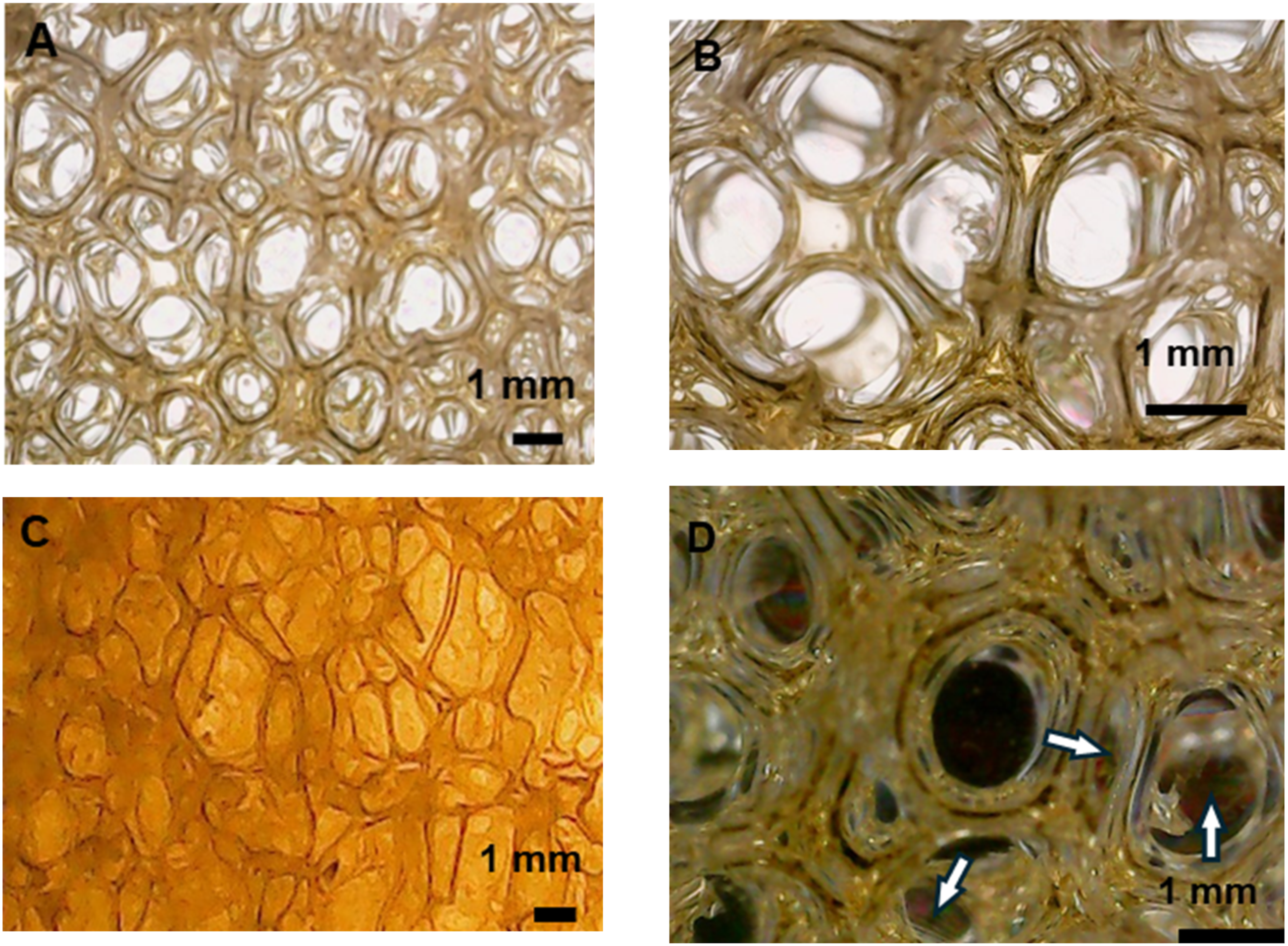

The three-dimensional reconstructed image of a sample by X-ray microtomography also suggests that the foam is composed of open and closed pores (Figure 6). Two 10 × 10 × 10 mm3 cubic samples are analysed, yielding total porosities of 88.71% and 88.10% for samples 1 and 2, respectively. Faces between adjacent cells can be identified (indicated by the arrows). The voxel size in these analyses is 27.6 μm. It is worth noting that structures on the order of, or smaller than, the voxel size cannot be reliably identified in a computed tomographic reconstruction, so that structures should be at least twice the voxel size to be reliably detected.35,36 Therefore, faces (or pores) with dimensions below 55.2 μm may be present. Only the total porosity obtained from microtomography is presented here, as X-ray micro-computed tomography tends to underestimate closed porosity due to partial-volume effects and limited spatial resolution. 37 When cell wall thickness falls below the voxel resolution limit (approx. twice the voxel size), solid membranes are often misclassified as void space during segmentation, artificially increasing the calculated interconnectivity (open porosity). While limited spatial resolution may result in an underestimation of closed-cell content by failing to detect sub-micron cell walls due to the partial-volume effect, the measurement of total porosity remains more robust. Unlike topological connectivity, the volumetric calculation of total porosity is substantially less sensitive to the omission of thin membrane features, as reported by Kerckhofs et al. 38 The foam morphology will also be investigated soon using scanning electron microscopy and gas picnometry (not yet performed due to temporary technical issues).
Using ImageJ, the edge (strut) thickness is roughly estimated at 0.24 ± 0.05 mm from optical microscopy images. Ten measurements are obtained from each image, except from Figure 5(d), in which the magnification is higher, and the focus is set to observe thinner cell faces under polarized light. It is worth noting, however, that the strut thickness obtained from microtomography is slightly higher (0.31 ± 0.08 mm), as lower resolutions tend to overestimate strut thickness.37,38
Parameters measured by microtomography.

In order to determine DA, the analysing software passes a grid of lines through a spherical volume of the material at a large number of 3D angles. The spherical volume is composed of solid portions and voids; for each angle, the software counts the number of times each line intersects the solid phase and calculates the ratio of the total length of the lines to the total number of intersections. This parameter is called the mean intercept length (MIL), which is represented in a polar plot as a function of the angle, forming an ellipsoid, called the anisotropy ellipsoid, represented by a second-order tensor. The eigen analysis of this tensor provides the three orthogonal eigenvectors and eigenvalues that describe the anisotropy ellipsoid. These eigenvalues are related to the MIL in each of the orthogonal axes, characterised by the eigenvectors. The ratio between the maximum and minimum eigenvalues yields the degree of anisotropy (DA). The closer DA is to unity, the closer the ellipsoid is to a sphere, and the more isotropic the material is.
The anisotropy index obtained indicates that the foam exhibits mild anisotropy, which may be associated with the absence of catalysts. The slow curing rate allows surface tension and viscosity to dominate over the rise-induced deformation typically observed in rapidly expanding commercial foams, allowing cells to relax to the lowest-energy, sphere-like shape. This quasi-isotropic response of the fabricated foam may be advantageous for multiaxial loading scenarios, such as core materials in complex sandwich structures or random-impact energy absorbers, where direction-independence of properties is required.
It is worth noting that the shape anisotropy index R could be also obtained based on the elastic compressive modulus in the parallel and perpendicular directions for a given replicate. 25 However, given the differences in mean density in the parallel and perpendicular directions due to the manual fabrication process, which affects the compressive modulus, this method is not used. The analysis based on microtomographic data is based on the dimensions of the struts and does not suffer from limitations imposed by density discrepancies.
The total porosity 
Considering the bulk density obtained considering all samples (from compression and bending tests) of the fabricated foam (125 ± 23
Additional insights into the microstructure and behaviour can be obtained from the mathematical modelling of the foam, as discussed below.
Modelling the foam using the Gibson-Ashby model
The stress-strain curve of the fabricated foams is consistent with the mechanical behaviour of closed-cell foams. In this work, the foam model proposed by Gibson and Ashby for closed-cell foams is used.
25
The model is useful to better understand how the geometric and physic mechanical parameters (such as relative density and elastic modulus of the solid material from which the foam is made) affect the mechanical properties of the cellular structure. Modelling also provides additional insights into the characterization and mechanical behaviour of the fabricated foam. The elastic modulus of closed-cell foams includes contributions from edge bending and face stretching. Owing to its quasi-isotropic behaviour, the foam is considered as an array of cubic cells of length l, edges (struts) of thickness 
The volumetric fraction of solid material located at cell edges (
It is worth mentioning that, considering the parameters obtained in this study (
The volume fraction 

The second term arises from gas compression inside the closed cells, which depends on the strain 

The parameter 

For the fabricated foam,
Conclusion
A rigid, catalyst- and surfactant-free castor-oil-based PU foam is fabricated using a straightforward fabrication method. Even though the cream (15–20 min) and tack-dry (2 h) times are long, since no catalysts are used, the elastic modulus (9.08 ± 0.71 MPa) and the elastic collapse stress (405 ± 29 kPa) under uniaxial compressive loads are comparable or higher than those found in the literature for rigid, closed-cell castor-oil PU foams, at the same bulk density range (128 ± 10 kg/m3). The foam is essentially isotropic with a shape anisotropy index close to unity, and the flexural elastic modulus under three-point bending is 9.2 ± 1.5 MPa. The foam shows potential for use as a secondary structural material in civil engineering applications, such as internal walls and partitions, and automotive engineering. Future studies will explore its thermoacoustic insulation performance and the effects of adding reinforcing particles and flame-retardants.
Footnotes
Acknowledgements
The authors acknowledge the Brazilian Research Agency CAPES for the MSc scholarship, CNPq (PQ-305553/2023-2, 4055062023-6), FAPEMIG (APQ-01007-25), and Universidad de Cantabria (LADICIM). The authors also thank Imperverg (Brazil) for kindly donating the castor-oil polyurethane used in this work.

Funding
The authors disclosed receipt of the following financial support for the research, authorship, and/or publication of this article: The authors acknowledge the Brazilian Research Agency CAPES for the MSc scholarship, CNPq (PQ-305553/2023-2, 4055062023-6), FAPEMIG (APQ-01007-25), and Universidad de Cantabria (LADICIM).
Declaration of conflicting interests
The authors declared no potential conflicts of interest with respect to the research, authorship, and/or publication of this article.