
Abstract
This study created metal/polymer cellular composite materials in which nanocrystalline Ni was electrodeposited on foamed microtruss polymer cores. The objective was to create a new composite cellular microtruss material in which the mechanical properties were controlled by an interconnected network of conformable nanocrystalline tubes. Batch CO2 foaming of the polymer core resulted in a microcellular foam architecture inside the microtruss struts, which had a lower density than the starting rapid prototyped pre-form. Foaming allowed a larger specific strength and the specific stiffness increases after electrodeposition than was possible on the starting polymer core alone.
Introduction
Microtrusses designed for use as cores in sandwich structures have received much attention recently. These lattice materials are open-cell systems that make use of a truss-like geometry in order to reduce the overall amount of material, allowing greater strength-to-weight and stiffness-to-weight ratios compared to conventional metallic foams.1,2 A considerable range of synthesis methods have been developed to produce microtruss cellular materials. 1 Several of these microtruss synthesis methods involve rapid prototyping because it can fabricate complex structures that are difficult to be produced using conventional machining and manufacturing methods. 3 Rapid prototyped cores have been used as a starting template for investment casting4,5 and as a template for electrodeposition.6,7 In the case of investment casting, the rapid prototyped component is used as a sacrificial pattern, which is first coated in a ceramic slurry, and then removed by heating to produce a hollow cavity for subsequent metal casting. In the case of electrodeposition, the rapid prototyped core is first metalized to give a conductive surface upon which electrolytic deposition can occur.
Two recent studies illustrate the combination of electrodeposition and rapid prototyping to create metal/polymer composite microtruss cores. In one case, conventional polycrystalline Ni was electroformed on pyramidal, tetrahedral, and strut-reinforced tetrahedral cores. 7 Electrodeposition provided the desired effect of increasing the strength and stiffness of the rapid prototyped cores. However, the increase in strength was not large enough to overcome the weight penalty associated with the electrodeposited Ni layer and there was, consequently, a small reduction in the overall specific strength. 7 On the other hand, if crystallite nucleation is dramatically favored over growth during the electrodeposition stage, a nanocrystalline structure can be produced, which takes advantage of the enormous Hall–Petch strengthening that can be obtained by grain size reduction down to the nanometer scale. For example, a yield strength of 86 MPa has been reported for conventional polycrystalline Ni having a grain size of 10 µm, 8 while electrodeposited nanocrystalline Ni with a grain size of 10 nm has a yield strength of 910 MPa. 9 Accordingly, much larger increases in both the yield strength and the specific strength can be obtained when nanocrystalline Ni is electrodeposited on a rapid prototyped microtruss core; for example, a 57-µm thick coating of nanocrystalline Ni increased the peak compressive strength of an acrylic photopolymer microtruss by a factor of 35 and increased the specific strength by a factor of 3.7. 6 While the polymer core in this case did not contribute much to the overall load-carrying capacity of the metal/polymer hybrid, it did serve a structural function by distributing the nanocrystalline metal away from the neutral bending axis of the composite struts. While increasing the diameter of the starting rapid prototyped polymer struts increases the structural efficiency of the electrodeposited nanocrystalline sleeve, it also represents an increasingly significant weight penalty. This study looks at the potential for foaming rapid prototyped microtruss cores prior to nanocrystalline electrodeposition in order to reduce the weight penalty associated with the starting polymer core.
Experimental
The hybrid nanocrystalline microtruss materials of this study were created in three steps. First, a fused deposition modeling (FDM) method was used to build the starting acrylonitrile butadiene styrene (ABS) microtrusses (at Proto3000, Toronto, ON) using the computer-aided design (CAD) model shown in Figure 1(a) (sample size 22.8 × 22.8 × 10 mm3). The internal strut dimensions were 3.1 × 3.1 × 7.3 mm3 and were oriented at an angle of 45°. Next, the as-received samples were foamed using a batch-foaming approach. The foaming process used in this study was performed in a two-stage batch process. In the first stage, the polymer samples are saturated in a high-pressure chamber at room temperature with a nonreactive gas such as carbon dioxide. In the second stage, the pressure is released and the samples are quickly heated to a temperature high enough to soften the polymer. The thermodynamic instability in the gas-saturated polymer causes cell nucleation and growth and results in foams with cell sizes in the order of micrometers.
10
CAD model of microtruss used in FDM and typical electrodeposited microtruss (sample type n-Ni/ABS).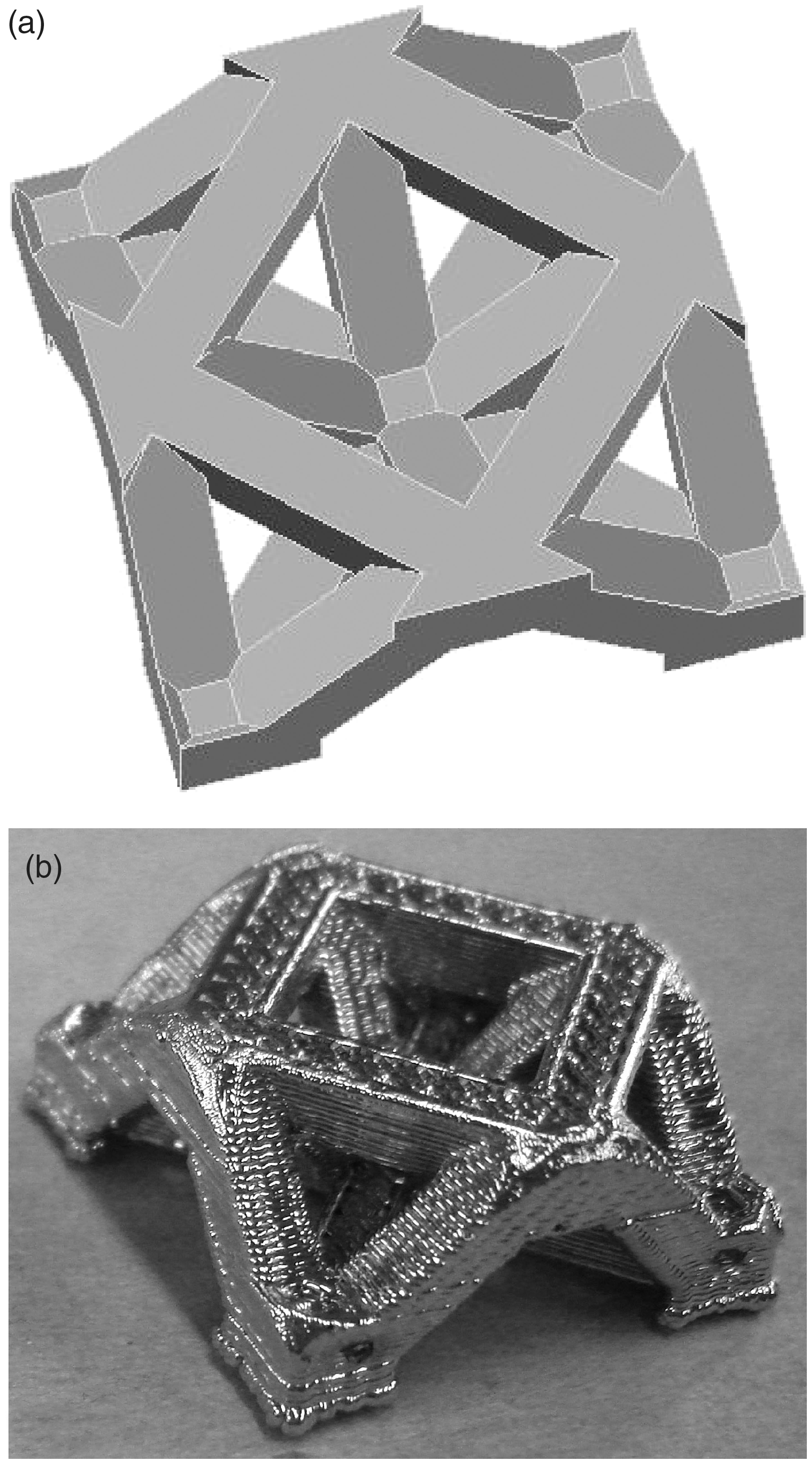
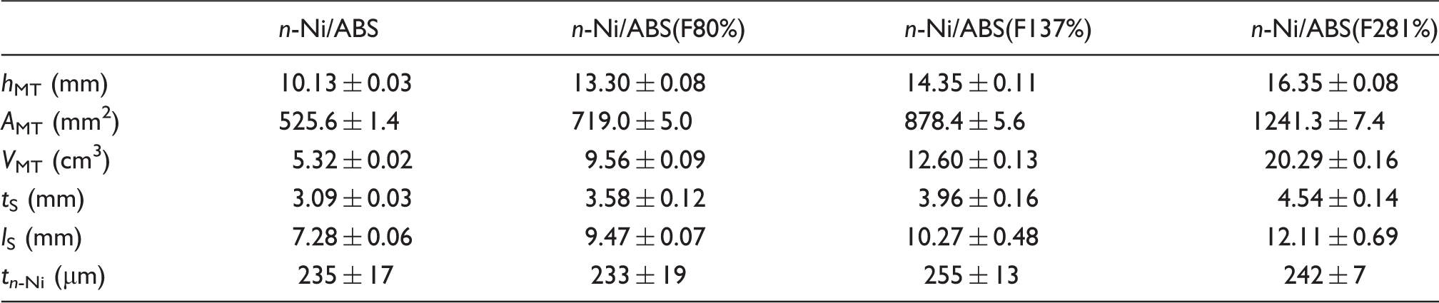
Geometric parameters of the nanocrystalline Ni/polymer microtruss hybrids, summarizing the starting polymer microtruss height (hMT), area (AMT), and volume (VMT), the starting polymer strut thickness (tS) and length (lS), and the nanocrystalline Ni coating thickness (tn-Ni)
The microcellular foam structure was characterized by shear fracturing the foamed microtrusses in liquid nitrogen, coating the fracture surface with gold, and examining it under the scanning electron microscope (SEM). The SEM was also used to characterize the failure mechanisms in the electrodeposited microtrusses after uniaxial compression testing. Confinement plates (steel platens having machined recesses, details in Bouwhuis et al.) 12 were used to mechanically lock the microtruss nodes in place, simulating the behavior the microtruss cores would experience as part of a larger sandwich panel. 12 All compression tests were performed using a Shimadzu AG-1 load frame at a constant displacement of 1 mm/min and the samples were tested until the microtruss struts failed. Compressive strains were estimated from the crosshead displacement 13 – 15 and calculated based on the total sample height. The stiffness was calculated from the maximum slope of the curve before the initial peak, while the strength using the peak stress value. In the cases where there was no definitive peak, an intersection between the maximum slope before the first inflection point and the minimum slope after the first inflection point was used to determine the strength.
Results and discussion
Foamed microtruss materials
Six microtruss samples were foamed at each foaming temperature; the sample dimensions summarized in Table 1 are the average of at least three measurements per sample with the standard deviation in these measurements reported as the error. The expansion of the ABS microtrusses after batch foaming can be considered at two length scales. First, at the level of the overall sample dimensions, the microtruss area (AMT) increased by 37%, 67%, and 136% and the microtruss height (hMT) by 31%, 42%, and 61% after foaming at temperatures of 85°C, 90°C and 95°C, respectively. Overall, foaming had the effect of increasing the overall volume of the microtruss (VMT) samples by 80%, 137%, and 281%; this parameter was used to denote the different sample types (Table 1). The second length scale change was at the level of the individual struts making up the microtruss core. Foaming increased the strut length (lS) by 30%, 41%, and 66% and the cross-sectional dimension (strut thickness, tS) by 23%, 35%, and 51%. Note that the ratio of strut thickness to strut length decreased slightly from 0.42 for the as-prototyped samples to 0.38 ± 0.01 for the as-foamed samples.
The effect of foaming can also be considered in terms of the sample porosity changes. There were two types of porosities in the starting as-prototyped microtruss. First, the open-space volume fraction of the starting rapid prototyped microtruss was 0.33. In addition, there was open porosity inside the struts from the FDM process (filament weaving pattern is shown in Figure 2), which occupied ∼2.5% of the volume of the rapid prototyped strut. Foaming had the effect of introducing a closed-cell microporous architecture inside the FDM filaments, which was revealed by cryogenically fracturing the as-prototyped and as-foamed struts (Figure 3). The average cell size was of the order of ∼10 µm (Table 1), which is on a length scale that is typical of microcellular foams. The relative density of the material making up the microtruss struts, therefore, decreased from 0.97 in the as-prototyped struts to 0.58, 0.43, and 0.29 for the ABS(F80%), ABS(F135%), and ABS(F281%) samples, respectively.
SEM micrograph showing the FDM filament structure in the as-prototyped microtruss struts. SEM micrographs showing cryogenically fractured struts from the as-prototyped (a) and as-foamed microtrusses (foaming temperatures of 85°C (b), 90°C (c), and 95°C (d)).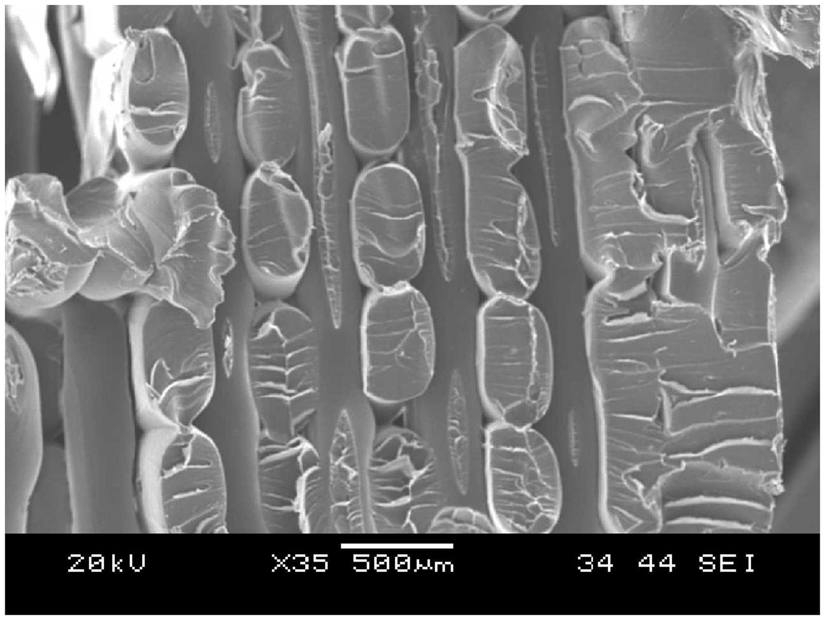
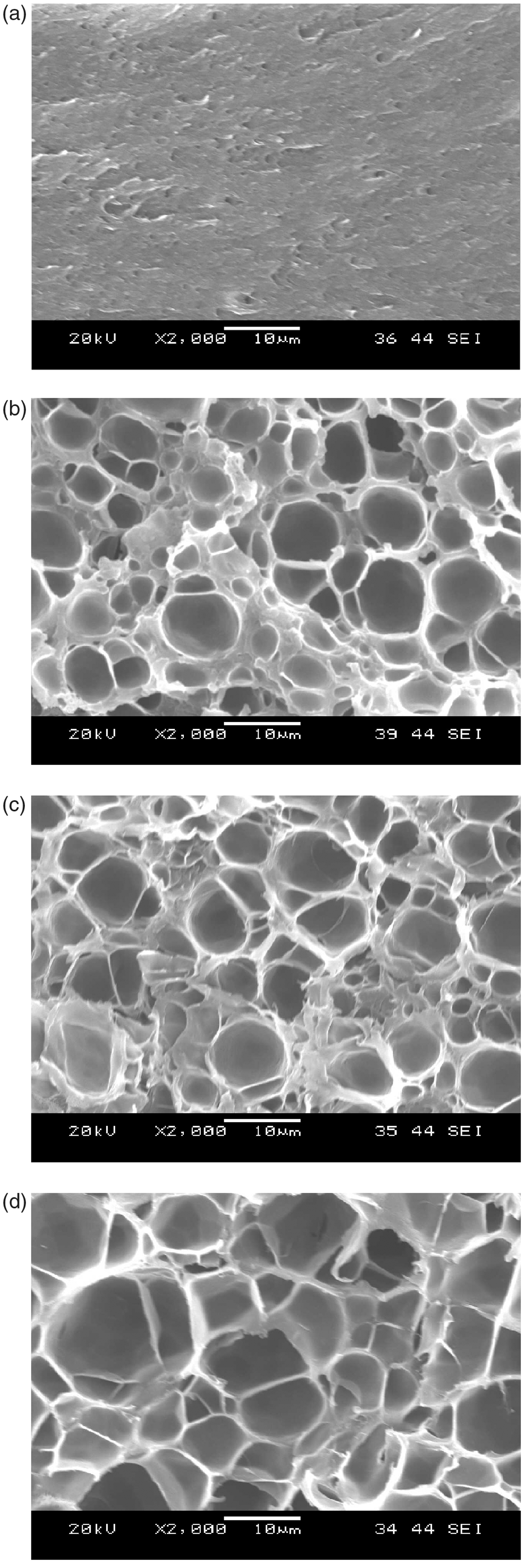
Figure 4 presents typical uniaxial compression stress–strain curves for the as-prototyped and as-foamed microtrusses. In each case, there was an initial elastic region, after which the microtruss struts failed by inelastic buckling at a nearly constant plateau stress (Figure 4 inset). Note that the overall form of the as-prototyped and as-foamed stress–strain curves was similar to what is typically seen for polymer foams.
16
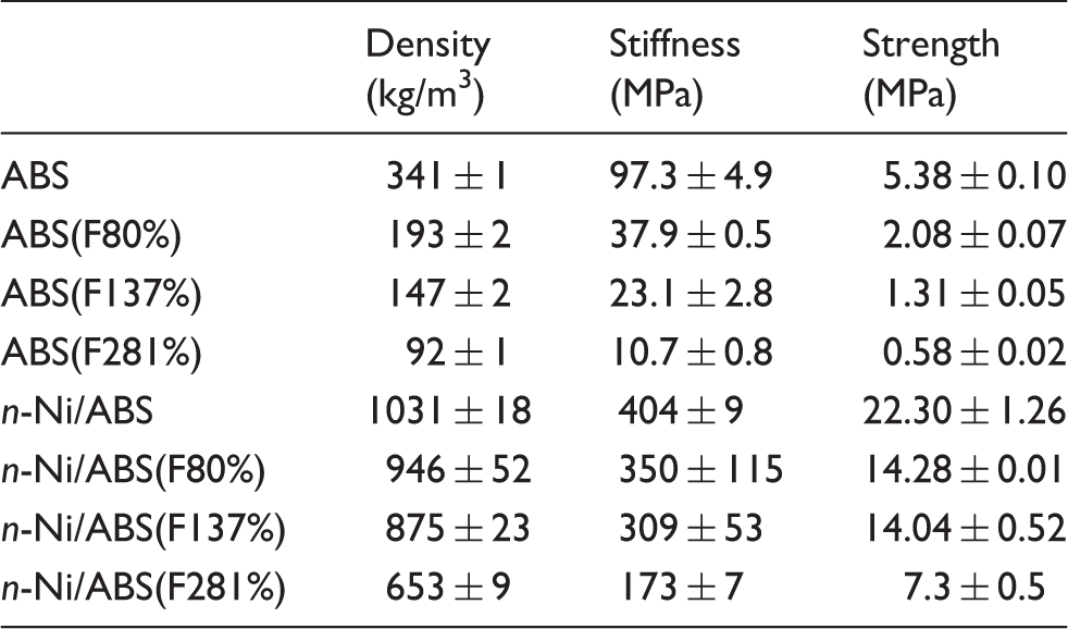
Foaming had the effect of decreasing both the initial compressive modulus (E) and the plateau stress (σp), Table 2. While the foamed samples also had a lower overall density than the as-prototyped truss, the density reduction was not enough to overcome the loss in strength and modulus: the specific stiffness E/ρ and the specific strength, both decreased with increasing volume expansion, e.g., σp/ρ decreased from 1.58 × 10⁻² MPa m3/kg for the ABS samples to 1.08 × 10⁻² MPa m3/kg for the ABS(F80%) samples.
Typical stress–strain curves for the as-prototyped and as-foamed ABS micro-trusses. Notes: Compressive modulus, plateau strength, and density values are summarized in Table 2. Failure occurred by inelastic buckling of the polymer struts (inset). Mechanical test data summary for the as-prototyped (ABS), foamed (e.g., ABS(F80%), and nanocrystalline Ni electrodeposited (e.g., n-Ni/ABS(F80%)) samples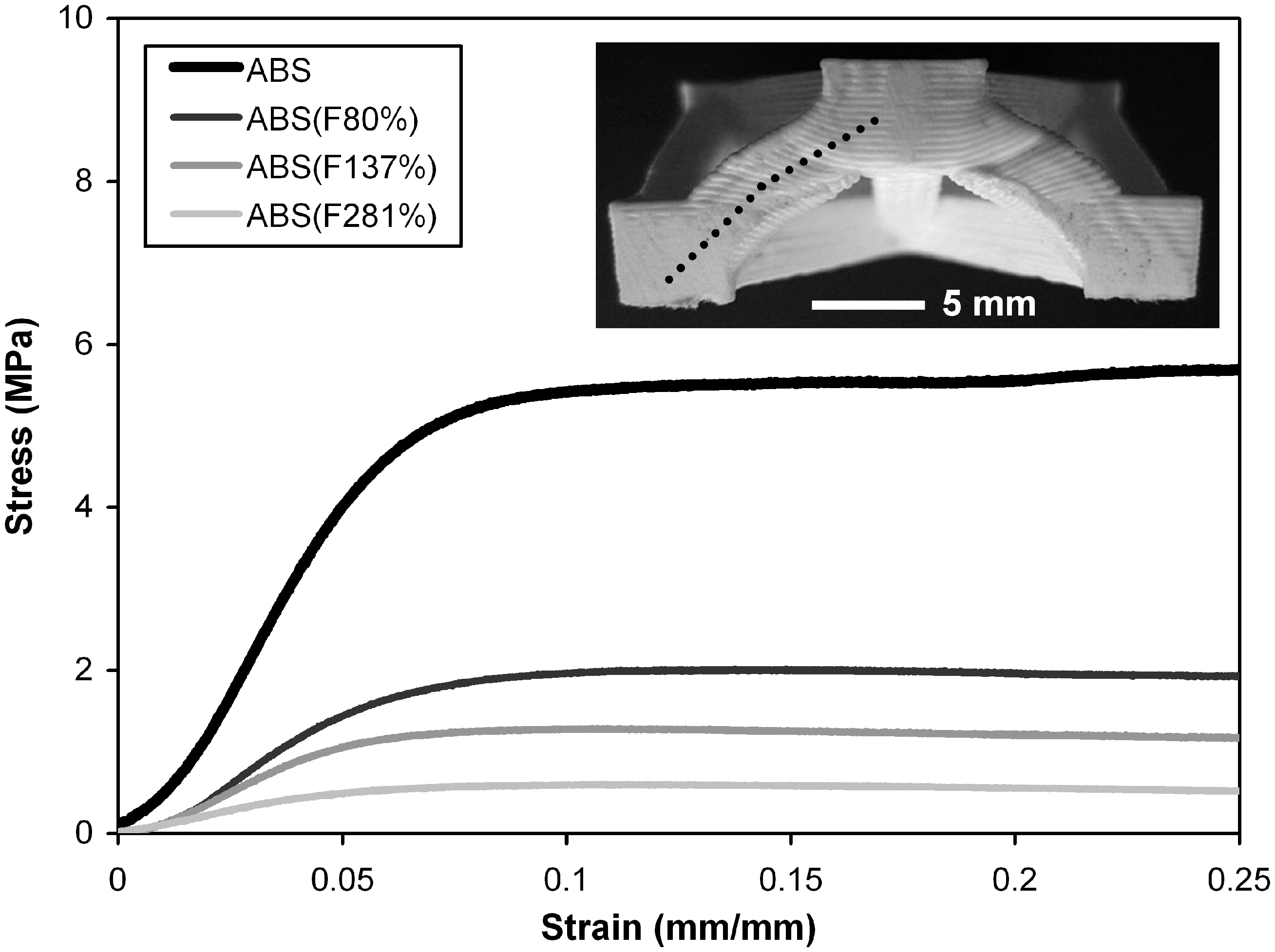
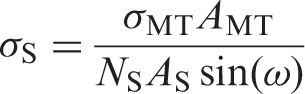
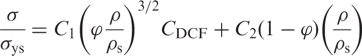
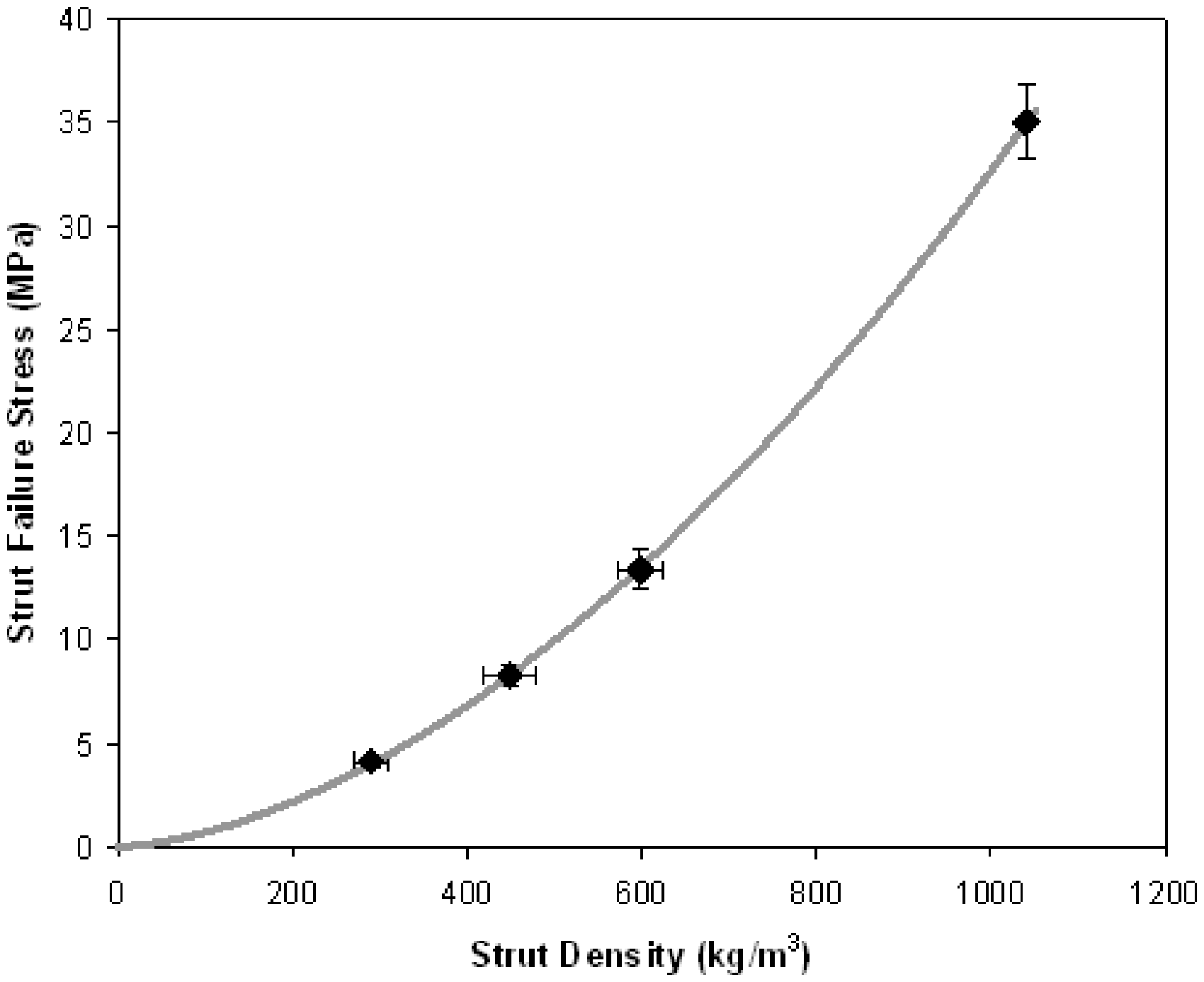
Foaming had the effect of changing both the geometric and material properties of the microtruss struts. From a geometric standpoint, foaming significantly increased the moment of inertia of the microtruss struts (e.g., by 395% for the ABS(F281%) samples), but the slenderness ratio of the struts, which provides a measure of the structural instability, was nearly constant at 8.5 ± 0.3. From a materials standpoint, however, the strength of the foamed material was much lower than the strength of the starting rapid prototyped material. The reduction in compressive strength can be considered in terms of the failure stress in the struts and the expected yield strength of the foam making up the struts. The resolved stress inside the microtruss struts can be expressed as:
Resolved strut failure stress as a function of the strut density for the as-prototyped and as-foamed samples of this study (data points) and corresponding Gibson–Ashby model (solid line
17
).
Electrodeposited microtruss materials
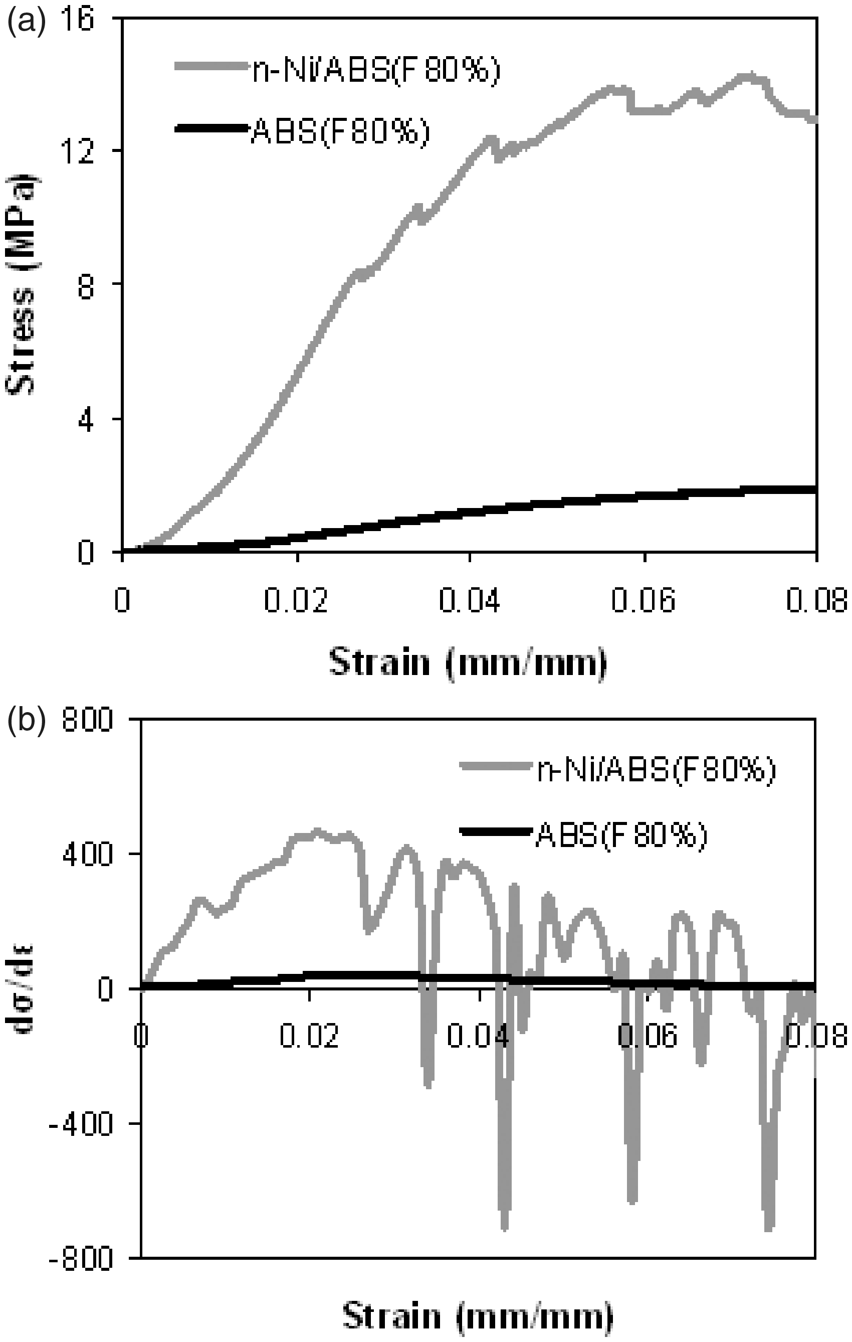
Figure 6 presents the uniaxial compression stress–strain curves for the electrodeposited microtrusses. The nanocrystalline Ni coating had a significant effect on both the elastic modulus and strength of the hybrid microtrusses. For example, the modulus and the strength were ∼315% higher for the n-Ni/ABS samples than the as-prototyped ABS samples (values for all sample types are summarized in Table 2). Failure of the nanocrystalline sleeves occurred by sleeve fracture at the point of intersection between the adjacent struts (Figure 6 inset). The onset of fracture could be seen as a series of small load drops prior to the peak compressive strength, which could be more easily identified by plotting the slope of the tangent of the stress–strain curves against the strain in Figure 7. Beyond the peak stress, the load drops became greater as the nanocrystalline nickel coating began to fracture and delaminate from the ABS microtruss core. This extensive delamination of the nanocrystalline coating from the polymer core during the final collapse sequence of the hybrid is not surprising given the comparatively low interfacial adhesion expected at the metal/polymer interface.
Representative stress–strain curves for the electrodeposited microtrusses. Notes: Compressive modulus, plateau strength, and density values are summarized in Table 2. Failure occurred by nanocrystalline sleeve fracture at the strut intersections (inset). Initial elastic region of the stress–strain curves for electrodeposited (n-Ni/ABS(F80%)) and as-foamed reference (ABS(F80%)) microtruss samples (a) and the derivative to the stress–strain curve which more clearly illustrates the load drops near the peak compressive stress in the n-Ni hybrid (b).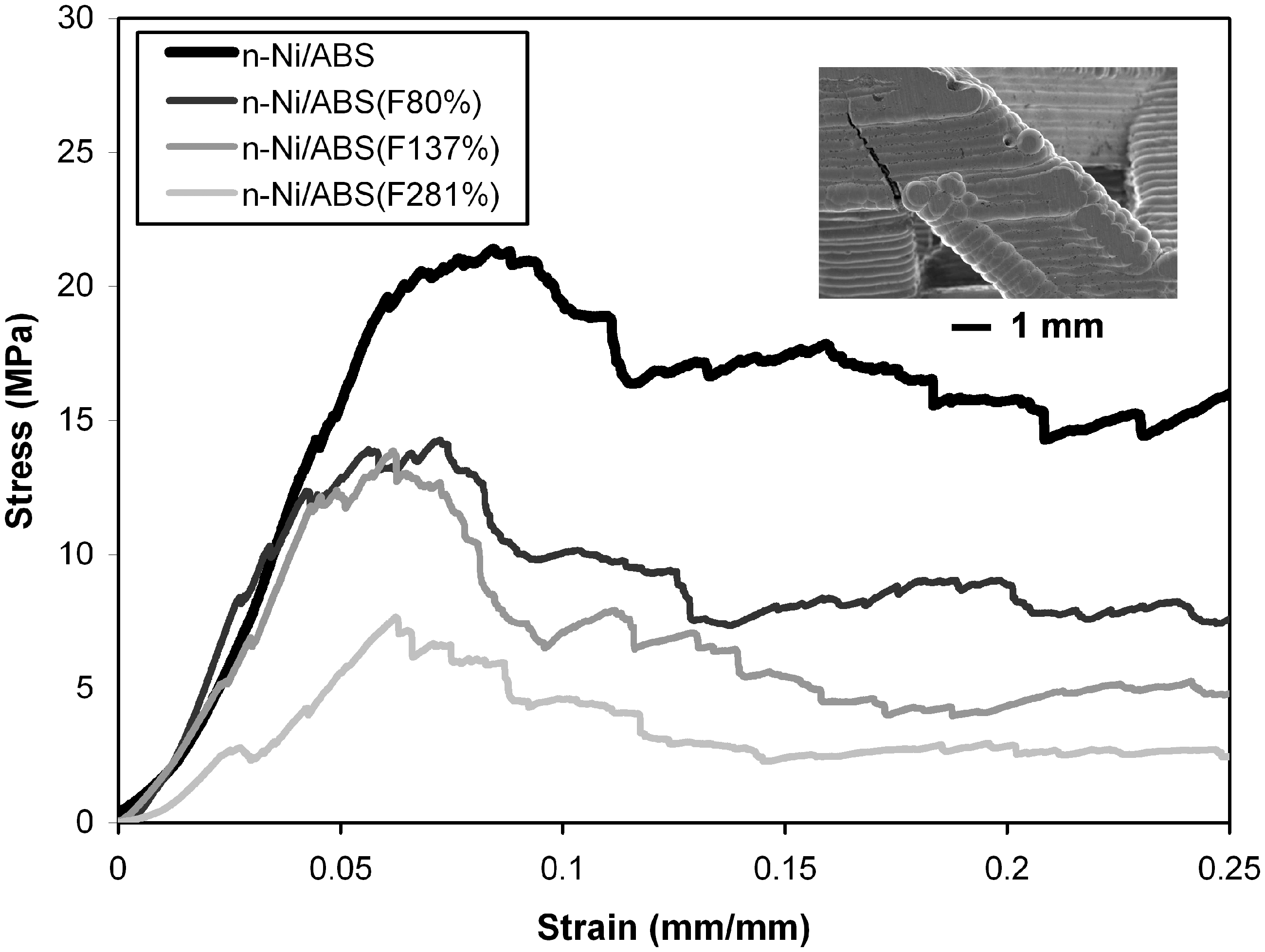
In previous studies, nanocrystalline electrodeposition has also been used to reinforce steel and aluminum microtrusses.18,19 In each case, adding the nanocrystalline sleeve significantly increased the compressive modulus and peak compressive strength. However, the strength of these metal/metal composite cellular materials was controlled by the relative sequence of architectural collapse (as indicated by the initial peak load in uniaxial compression) and the onset of fracture in the electrodeposited sleeves. For the case of n-Ni reinforced plain carbon steel microtrusses, there was no evidence of crack formation until after the peak stress had been reached. 18 In this case, the performance of the composite microtruss could be predicted using an isostrain approach in which the increase in strength provided by electrodeposition was modeled after the inelastic buckling performance of an interconnected network of hollow nanocrystalline tubes. 18 However, when electrodeposited on aluminum microtruss cores, sleeve fracture occurred before the peak strength, and the attainable performance increase was correspondingly reduced. 19 A similar effect of sleeve fracture occurring before architectural failure is observed in this study where the peak strength is controlled not by the buckling resistance of the composite metal/polymer struts but rather the sleeve fracture at the strut intersections.
Despite the early fracture of the nanocrystalline sleeves, electrodeposition still significantly increased the strength and stiffness of the composite microtrusses. In order to assess the relative weight specific performance of the composite microtrusses, the specific strength and specific stiffness ratios between the plated and the unplated samples were compared using the relationships below:
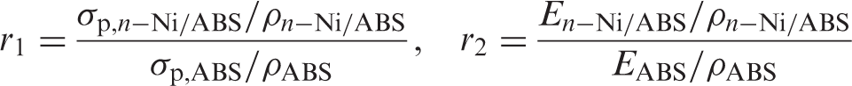
In this equation, if r is greater than 1, then the addition of the nanocrystalline nickel was beneficial on a weight specific basis. Figure 8 plots the values of r as a function of the foaming expansion for the samples of this study. In all cases, the normalized stiffness and strength ratios were greater than 1. Furthermore, the normalized ratio generally increased with increasing foamed volume expansion, indicating that on a weight specific basis, the electrodeposition step was most effective on the foamed core samples. While foaming did not significantly change the slenderness ratio of the starting polymer struts, it did have the effect of reducing the polymer strut density, which had a significant effect on the increase of weight specific mechanical performance that could be obtained after nanocrystalline electrodeposition.
Specific strength and specific stiffness ratios (Equation (3)) illustrating the increase in weight specific performance obtained by nanocrystalline Ni electrodeposition.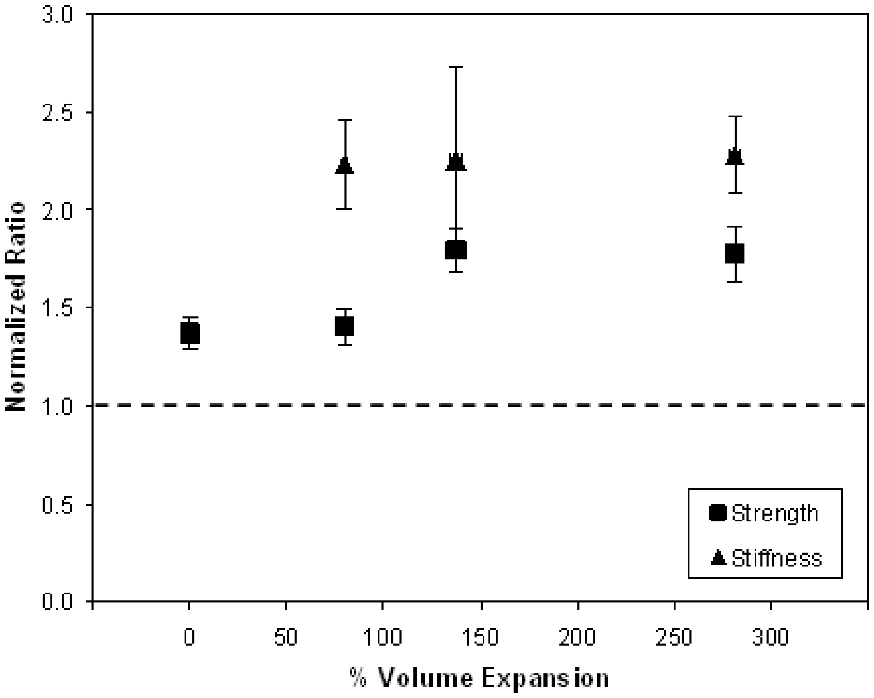
Conclusions
A new type of nanocrystalline metal/polymer foam composite microtruss material was developed in this study. Uniaxial compression testing showed that the plateau strength of the as-prototyped and as-foamed samples was controlled by the inelastic buckling resistance of the microtruss struts, while the strength of the electrodeposited samples was controlled by nanocrystalline sleeve fracture at the intersection of the microtruss struts. The electrodeposited hybrid materials had up to ∼1150% greater strength and ∼1500% greater stiffness compared to their unplated counterparts, while the weight specific benefits of nanocrystalline electrodeposition increased with increase in volume expansion during pre-electrodeposition foaming. Foaming the microtruss polymer cores prior to electrodeposition is one way to lower the parasitic mass of the starting template and may allow more structurally efficient nanocrystalline microtruss materials to be fabricated.
Footnotes
Acknowledgment
Financial support provided by the Natural Sciences and Engineering Research Council of Canada (NSERC) is gratefully acknowledged.