
Abstract
In-plane compressive strength of z-pinned unidirectional composites is predicted by using variational principle and maximum shear strength criterion. The fiber waviness and the fiber volume content concentration, which are inhomogeneously distributed, as well as the resin-rich pocket, are taken into account. The predicted results are in good agreement with the test data. The effects of pin parameters on the compressive strength of z-pinned laminates are discussed in detail. The results showed that in-plane compressive strength of laminates decreases as the diameter of pin increases under the same pin volume content. Compressive strength decreases as the pin volume content increases under the same pin diameter. The non-linear shear property of matrix has relatively remarkable influence on compressive strength of unidirectional z-pinned laminates when pin diameter is small.
Introduction
Low compressive strength and delaminating of aligned continuous fiber composites are of most concern in design of advanced composites. Compressive strength of unidirectional carbon fiber epoxy composites areoften lower than 60% of their tensile strength. 1 Imperfections including fiber waviness, voids, and cracks in matrix cause diversity of compressive failure modes. For unidirectional laminates, the degree of initial fiber misalignment and the plastic deformation of the matrix are dominated by two factors that govern their compressive strength. 2 It has been proved that inter-laminar properties can be clearly improved by z-pin reinforced in thickness direction.
However, the z-pinning not only causes the distortion and heterogeneous distribution of fibers which stimulate buckling or kinking of fiber but also forms a resin-rich zone around each pin which decreases the volume content of fiber.3,4 These conditions have adverse effects on in-plane properties, especially on compressive strength. Therefore, an important scientific and engineering issue is how to appropriately evaluate the loss of compressive strength caused by insertion of z-pins.
Some theoretical analysis and experiments have been done by researchers on this issue.3–11 Experiments showed that compressive failure mode of stitched laminate is almost the same as the failure mode of unstitched laminate under axial compressive load. 5 Mouritz 4 proposed a linear empirical formula to predict the compressive strength of z-pinned laminate which decreases at a linear rate with increasing volume content and diameter of pins. Li and Xu 6 presented a 3D fiber waviness model based on the finite element method and periodic boundary conditions. This model adopted a bridging model and the maximum stress criteria to predict the development of damage and the compressive strength of stitched laminate. Based on Cosserat couple stress theory, Fleck and Shu 7 presented a constitutive relationship for unidirectional fiber reinforced composites including fiber waviness. And a finite element analysis on compressive failure of polymer matrix by fiber microbuckling has been performed, showing that the compressive strength decreases with increasing imperfection (fiber waviness). In this model the fiber and matrix were not analyzed as discrete phases explicitly, and were idealized instead as a ‘smeared-out’ homogeneous solid of a Cosserat continuum capable of bearing couple stress. The 2D Finite Element Code (FLASH) developed by Fleck and Shu 7 has been used by O’Brien and Krueger 8 to predict the influence of compression and shear loads on the strength of composite laminates with z-pins. Results indicated that increasing the density of pins was more detrimental to in-plane compressive strength than increasing pin diameter. Steeves and Fleck 9 used the FLASH model to predict the influence of the pin arrangement pattern on pinned laminate. Their experiments and numerical simulations showed that the presence of through-thickness reinforcing pins decreases compressive strength of composite by at least 30%. Among the examined orientation angles of pins the 0° orientation angle has a minimized fiber alignment disruption and thereby maximizes compressive strength of z-pined composites. Huang and Waas10,11 established a 3D representative cell model to simulate z-pinned plain weave glass fiber textile composites, they studied the effect of the number of cells and layers on composite strength, figured out a relationship between angle of plies and composite strength.
In this work, a beam model including initial waviness will be developed and the fiber waviness model was based on the model given by Wei and Zhang. 12 The fibers and matrix are treated as discrete layers. Failure criterion of laminates is established on fiber and matrix scale. The influence of micro-structure (such as fiber waviness, resin-rich pocket, the volume content concentration) caused by insertion of pin, dilution of the fiber volume content due to swelling in consolidation process, and effect of non-linear shear properties of matrix are considered and studied in detail. In-plane compressive strength is obtained by using variational principle and maximum shear strength criterion.
Compressive strength model of z-pinned composites
Based on the technological process of z-pinning, pattern of pins can be supposed to be in periodic arrangement as shown in Figure 1(a). Because z-pinned laminate usually has a large size which contains sufficient numbers of cells, the edge effect could be ignored and one unit cellwith periodic boundary condition is chosen as a representative volume element. The length of cell is equal to the horizontal pin-spacing Lz and the width of cell to the vertical pin-spacing Hz. When the horizontal spacing Lz is the same as the vertical pin-spacing Hz, the square unit cell can be calculated as (a) Schematic diagram of pin arrangement
7
and (b) the half unit cell of z-pinned composite and global coordinate.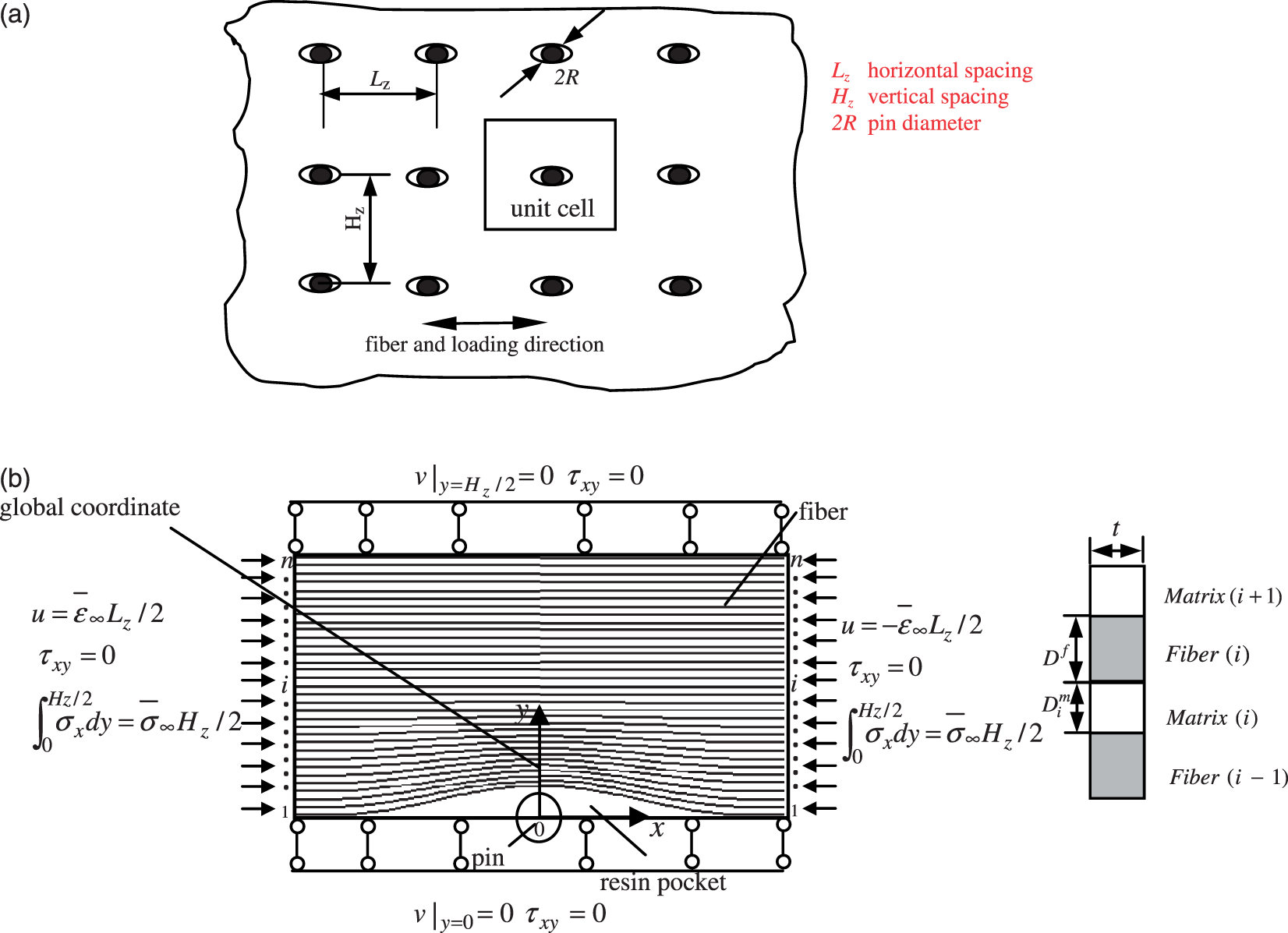
In the z-pinning process the pins are inserted into the laminate through the thickness and the fibers are forced to spread around the pins. The fiber orientation and fiber content in z-pinned composite laminates will vary from point to point in the distortion region. The fiber distortion model (FDM) has been developed by Wei and Zhang
12
for the prediction of misalignment angle of distorted in-plane fibers and inhomogeneous fiber volume fraction induced by stitching. Here, the FDM is used to quantitatively evaluate the in-plane fiber misalignment angle and fiber volume fraction at an arbitrary point in the z-pinned unidirectional compositeply. In the FDM model the initial path of the i-th fiber is represented by a cosine function 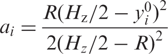
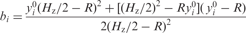
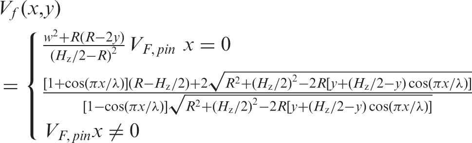

Hence, the general influence of laminate thickness and resin-rich field area on average fraction of fiber volume in z-pinned laminates can be expressed:

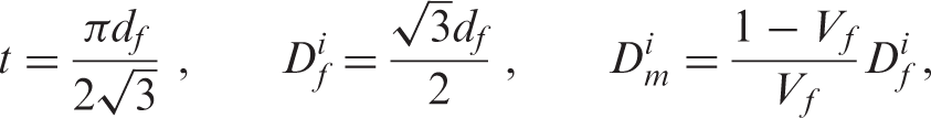
In the present 2-dimensional model the fiber andmatrix are treated as rectangular layers which are equivalent to real fiber and matrix in terms of the cross-sectional area, area moment of inertia and fiber volume fraction.
14
The corresponding equivalent parameters can be calculated as
For convenience in describing deformation of fibers and matrix layers a local coordinate y* whose origin is placed at the central axis of each fiber is used in Figure 2. For example, Deformation of fibers and local coordinate system.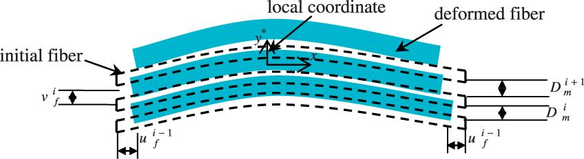
Because there exists initial fiber waviness caused by pin insertion, fibers under axial compressive stress are the most likely to produce deformation shown in Figure 2. So, we could assume shape function of fibers after deformation as below:

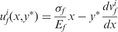
The axial displacement of fibers is composed of two parts. First, the fiber carries an axial compressive load, which gives rise to an axial compressive displacement. Second, because the fiber also carries bending moment, there is a corresponding bending component of axial displacement, which varies linearly through the thickness of the fiber. So, the axial displacement of the fibers can be given by Equation (8):
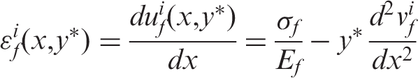
The local strains of the fibers have the following form:
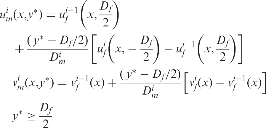
Assuming a perfect-bond between fiber and matrix before matrix failure, displacement continuity at the fiber/matrix interface should be satisfied. For the i-th matrix layer, the matrix displacement must match with the fiber displacement at the interface. Furthermore, the displacement in matrix layers is assumed to vary linearly in the transverse direction. Thus, the matrix displacements can be expressed as:

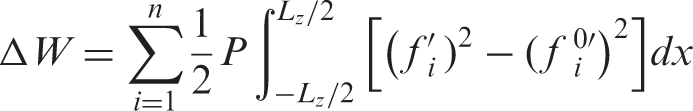
The mechanical work done in fibers under axial compressive stress according to the beam theory is written as
The total strain energy of fibers can be written:
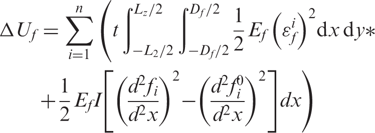
The first part of Equation (13) is the strain energy caused by axial compression, and the second part is the strain energy caused by fiber bending. For the matrix layers between fibers, the main deformation in matrix is assumed to be in shear and the strain energy is calculated according to the shear mode,
15
and the energy associated with axial deformation is ignored. In resin-rich pocket the main deformation in matrix is assumed to be in tension and compression according to an extensional mode presented by Rosen.
15
Hence, the total strain energy in matrix is given by:
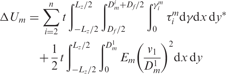
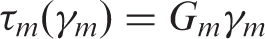
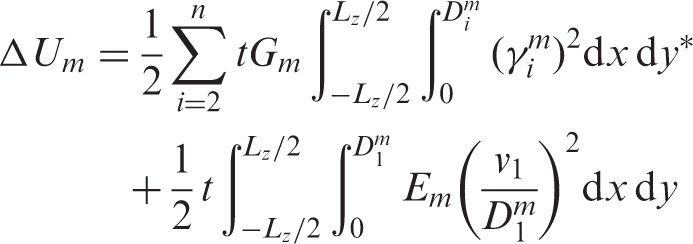
The explicit determination of Δ Um requires a shear-stress/shear-strain relationship for the matrix material. If the matrix material is assumed linear elastic, this relationship has the form
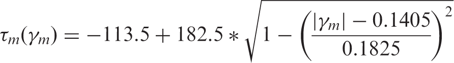
For the matrix material with non-linear shear behavior, the shear stress/strain relationship
16
for 914C resin is used to describe the non-linear behavior of matrix. The relationship is given by:
When this non-linear constitutive relation is used, the strain energy in matrix cannot be explicitly integrated, so Gauss numerical integration method along x-axis should be used. The total potential energy in the unit cell can be given by Π = Δ Uf + Δ Um + ΔW, using the variational principle and stationary value conditions, the expression of σf involving coefficient Ai can be solved.
Ewins and Ham have proposed that shear stresses generated in the laminate may be sufficient to cause a shear mode of failure in addition to composite failure due to buckling.
17
Using maximum shear stress principle, when the maximum shear stress on the fiber/matrix interface is up to shear strength of matrix, failure will occur, i.e. 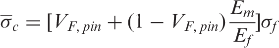
Analysis and discussion
Material properties
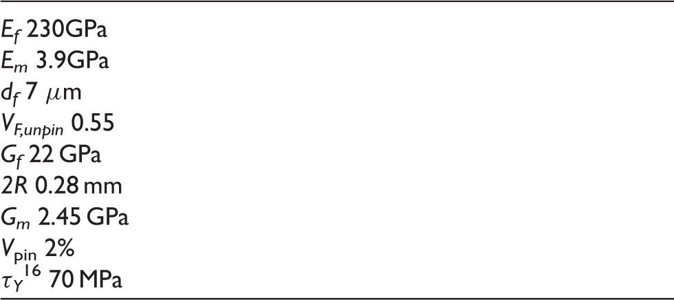
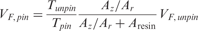
Comparison of test data and predicted value of z-pinned composite
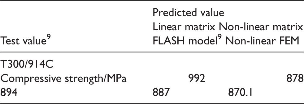
It can be seen from Table 2 that the agreement between predicted value from the present model and test value is acceptable. From the predicted values calculated by different constitutive relationships of matrix we can see shear properties of matrix has a considerable effect on compressive strength. The difference between the model and experiment is 11.0% when linear matrix constitutive relationship described by Equation (15) is used. The discrepancy is only 1.79% when non-linear matrix constitutive relationship described by Equation (17) is used. This indicates that the results which consider non-linear shear constitutive relationship of matrix have a better accuracy.
In order to further verify our theoretical model, a 2D finite element model of the same z-pin material system which has been examined in the theoretical model and listed in Table 1, will be established. The size of the representative unit cell is 1.75 mm. Due to the symmetry of the cell, only quarter of the cell is modeled in a two dimensional plane strain region using the ANSYS PLANE82 element. A finite element (FE) mesh is shown in Figure 3. The 80 fibers with non-uniform fiber spacing derived from the inhomogeneous fiber volume fraction (Equation (2)). The diameter of fiber and width of matrix layer is chosen as the height of one element (y-direction), the length of each fiber is divided uniformly into 45 elements. The same assumption that the properties of pins are the same as those of resin, which was used in theoretical model, is used. The region including the rich resin zone and pin is divided into 183 elements with the smallest size 0.00057 mm2.
Finite element (FE) mesh of the 2D plane strain unit cell (quarter).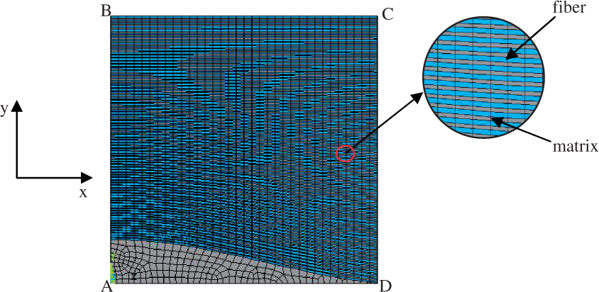
The matrix is simulated as an isotropic material for which the constitutive relationship is taken as the non-linear material described by J2 incremental theory of plasticity. The fiber is simulated as a transversely orthotropic material. As shown in Figure 3, the boundaries AB, AD are imposed by symmetry conditions. The boundary BC is set free to move in the Y direction during the compression loading. Boundary CD is used to impose an uniform displacement along the X direction.
The compressive failure analysis is carried out by using the similar method reported in references 18 and 19 and implemented by using the arc-length method supplied by ANSYS, reaction force at left edge can be computed for each increment of displacement. The overall σ − ε curves of the z-pinned composites can be obtained, Figure 4. The maximum stress (compressive strength) 870.1 MPa is reached. After peak point the stress–strain response of the Z-pinned composite is a unstable ‘snap back’. This could be explained by that the areas where exists fiber waviness caused by Z-pin undergoes shear deformation under compression. As shear deformation increases the matrix is yielded and soften, and the deformation localizes into a kink band with a corresponding load drop.18,19
Stress–strain curve of the carbon fiber composite with 2% pin volume content (Vf = 55%).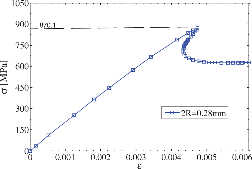
In the following analysis, compressive strength are all normalized by compressive strength of unpinned laminates which is 1541 MPa. 9
Influence of shear properties of matrix and pin’s diameter on compressive strength of unidirectional laminate with 2% pin volume content is shown in Figure 5. In-plane compressive strength of laminate decreases as the diameter of pin increases for a given pin volume content (say 2%). Especially, the fast reduction of compressive strength with pin diameter is observed when smaller pin diameter is used. When diameter of pin is larger than a certain value, roughly say 0.6 mm, further reduction of compressive strength is relatively slow. The reason is that shear stress in matrix can reduce the compressive strength by promoting micro-buckling and kinking with increasing of amplitude of fiber waviness (in connection with diameter of pin). When diameter of pin is up to critical value, increase of local fiber volume content makes fibers closely spaced, which slacks down the effect of shear stress in matrix between fibers. The influence of non-linear shear properties of matrix on compressive strength is obvious for small diameter of pin. This conclusion was also seen in Table 2 where the pin diameter is 0.28 mm.
Effect of diameter of pin on compressive strength with 2% pin volume content.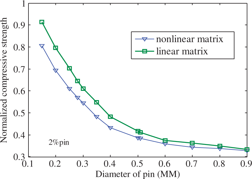
Influence of pin volume fraction on compressive strength of unidirectional laminate is shown in Figure 6. The plot shows the relationship of pin volume fraction and compressive strength for two kinds of pin’s diameter, which are used in engineering. It is shown that compressive strength of composite reinforced by both thinner pin and bigger pin decreases at a linear rate with increasing of pin volume fraction. It is seen that the rate of reduction of the compressive strength against the pin volume fraction for the bigger diameter of pin is smaller than the rate of reduction for the thinner diameter pin. That means that the influence of pin volume fraction on compressive strength is more notable for smaller pin.
Effect of volume content of pin on compressive strength.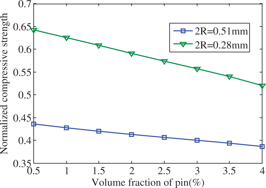
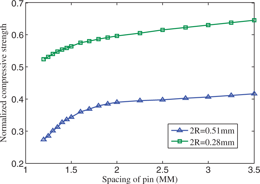
Influence of initial fiber volume fraction on compressive strength of unidirectional laminate with 2% pin volume content is shown in Figure 7. It can be seen that compressive strength of z-pinned laminate increases with increasing of fiber volume fraction under the same diameter of pin and pin volume fraction. It also could be seen that the fiber volume fraction has more significant influence on compressive strength of laminate reinforced by smaller pins. Influence of pin spacing on compressive strength of unidirectional laminate is shown in Figure 8. It can be seen that compressive strength increases gradually as the pin spacing increases.
Effect of volume content of fiber on compressive strength with 2% pin volume content. Effect of pin spacing on compressive strength.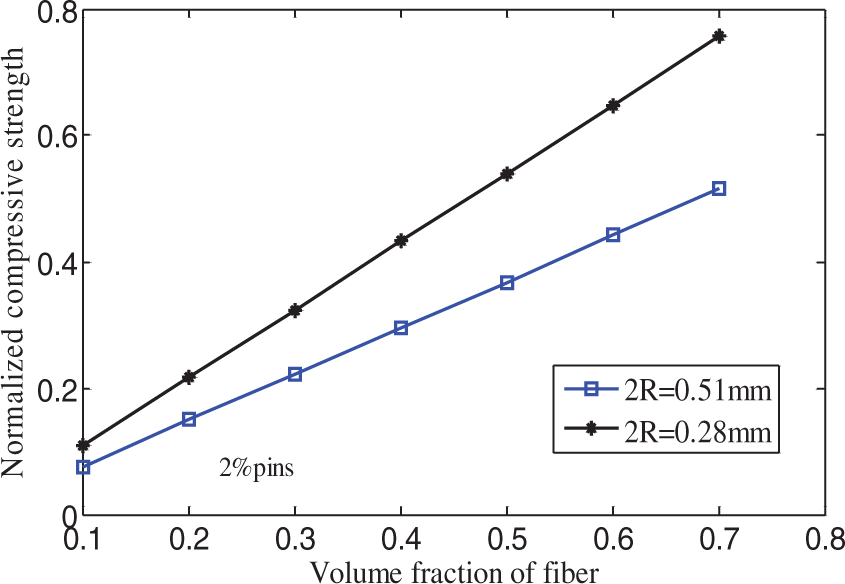
Conclusions
A model for prediction of the in-plane compressive strength of z-pinned unidirectional composites has been developed which takes into account the influence of micro-structural changes caused by z-pinning. Predicted results have a good agreement with test data. Results have shown that the presence of through-thickness reinforcing pins decrease the compressive strength of composites. In-plane compressive strength decreases gradually with increasing volume content and diameter of z-pins. The influence is clear when diameter is smaller than 0.6 mm. Under the same pin volume content, smaller pin has a lesser loss on the compressive strength than bigger pin. The reduction in strength with increasing pin diameter (for a fixed pin content) is due tothe higher waviness of the fibers. The compressive strength decreases with decreasing pin spacing for given pin diameter. Pin’s space decreasing makes it easier for the kink band to propagate unstably between pins. The non-linear shear property of matrix has obvious effect on compressive strength of laminates especially for the smaller pin diameter.
Footnotes
Acknowledgments
The authors gratefully acknowledge the financial support of the National Science Foundation of China under grant number 10772105 and the support of Shanghai Leading Academic Discipline Project under number S30106.