
Abstract
In this study, randomly organized and uniaxially aligned polyacrylonitrile (PAN) nanofibers with an average diameter of ∼550 nm were prepared by electrospinning. They were embedded into poly(methylmethacrylate) (PMMA) to fabricate reinforced composite films by solution impregnation technique. Though the PAN nanofibrous mats were white in color, and fiber contents in composites were as much as 16 wt%, and the refractive index (RI) was different between PAN (RI = 1.5187) and PMMA (RI = 1.489), the composite films showed excellent optical transparency with as high as 90% light transmittance in the visible light range, regardless of the fiber orientation. The mechanical properties of composite films steadily improved with nanofiber contents, and were dependent on the fiber orientation. The tensile strength and Young’s modulus of the composite film containing 16% aligned fibers were respective 40% and 30% more than that with the corresponding amount of randomly organized fibers. The embedding of PAN nanofibers displayed no effect on the glass transition temperature of PMMA matrix, but increased the stiffness of the composite films in the glassy and glass–rubber transition state, as demonstrated by the dynamic mechanical analysis. This optically transparent PMMA composite with improved mechanical strength may be potentially used as the windshield for the highly moving objects.
Introduction
Optically transparent composite plastic films reinforced with polymeric fibers have attracted much research attention in recent years, due to their good mechanical strength and potential applications in the structural materials of highly moving objects like aircraft windshileds, and electronic device. 1 – 6 In these studies, high fiber loadings of up to 60 wt% in the composites are often necessarily to obtain mechanically strong materials. Such large fiber contents would normally lead to severe light reflection/refraction on the fiber/matrix interfaces. In order to minimize the light loss caused by the reflection/refraction, the reinforcing fiber should either possess a refractive index (RI) closely matching to that of the polymer matrix to a third decimal place, or be as small as one-tenth of the wavelength of visible light. 1 So far, the fiber-matrix pairs with such a close RI are very limited. However, many types of nanofibers can be easily fabricated due to the fast development of nanotechnology.
Nanofibers made by electrospinning technique show outstanding features of large specific surface areas and relative good mechanical strength. Most importantly, this technique provides a facile top-down method in the massive fabrication of nanofibers to meet practical applications. 7 Because light loss caused by the reflection/refraction on the nanofibers is very small, electrospun nanofibers have been used as reinforcing fibers in the fabrication of optically transparent composites. For example, Krauthauser et al. 8 reported electrospun nylon-6,6 nanofibers reinforced epoxy and vinyl ester resins. A model was developed for the relationship between light transmittance and fiber volume fraction, fiber diameter, refraction indices of both fiber and matrix. Cellulose nanofiber reinforced poly(vinyl alcohol) (PVA) composite film with high visible light transmittance were reported. 9 With 40 wt% fiber content in the PVA composite, its mechanical strength and Young’s modulus were increased by 50% and 600%, respectively. Electrospun cellulose acetate nanofibers, polyurethane, cellulose acetate/polyurethane fiber reinforced epoxy composite films were also fabricated. 10 The mechanical strength of cellulose acetate nanofiber/epoxy composite with fiber content of 23% increased by 3.4 times compared to that of neat epoxy resin.
Poly(methyl methacrylate) (PMMA) is a hard and rigid material with excellent optical transparency. However, it is brittle under impact conditions. This is a drawback when used as a structural component in highly moving objects. In order to enhance the mechanical properties of PMMA while maintaining transparency, PMMA composites reinforced with electrospun nanofibers have been developed recently. For example, Chen et al. 11 fabricated transparent PMMA composites by hot pressing coaxial electrospun PMMA(sheath)/Nylon-6(core) nanofibrous mats. The composites showed a sacrifice of 10% in transparency, but an increment of more than 20% in the mechanical properties. Matabola et al. 12 studied the single polymer composites of PMMA reinforced with electrospun PMMA fibers of 200–900 nm in diameter by hot press treatment. 12 They found that the storage modulus of the composite with a 10 wt% nanofiber loading was increased by 83% compared to the neat PMMA matrix. In the case of transparent PMMA/Nylon-6 composite film, the loading content of Nylon-6 nanofiber is 3.5 wt% only. 11 With regard to the low fiber loading, somehow it is not a very surprise to make a PMMA/Nylon-6 composite film with good optical transparency. For the single component PMMA composites reinforced with electrospun PMMA nanofibers, 12 their optical transparency is expectable because there is no refractive index difference between the reinforcing fiber and the matrix.
It is interesting to increase the fiber loading in the composite in an attempt to greatly improve its mechanical properties. Also the application of reinforcing nanofibers with a different RI from that of matrix PMMA can help elucidate the effect of RI on the light behaviors of the composite. Moreover, the optically transparent composites reinforced with electrospun nanofibers reported in most literatures are randomly oriented. 13 One may expect to use aligned electrospun nanofibers as reinforcing fibers for the fabrication of transparent composite materials with superior mechanical properties than when the randomly organized fibers are used.
Polyacrylonitrile (PAN) fibers possess better elastic modulus than conventional polyester and nylon fibers. They show very good light- and solvent-resistant and thermal stability properties. Therefore, PAN nanofibers have shown many applications in fields such as reinforcing fibers in dental composite, 14 absorbent materials15,16 and the precursor of carbon fibers. 17 In this study, the aligned and randomly oriented electrospun PAN nanofibers with diameters about 550 nm are used as reinforcing fibers in PMMA matrix. Optically transparent PAN fiber/PMMA composites are prepared through solution impregnation technique with a fiber loading of up to 16 wt%. The morphology, mechanical properties, dynamical mechanical properties, and light transmittance of the composite films are characterized in relation to the loading, alignment, and RI of PAN fibers. The purpose of this work is to increase the mechanical strength of PMMA while maintain its transparency by using a relative high loading of electrospun PAN nanofibers, which has a different refractive index from that of PMMA matrix; and to evaluate the effect of fiber alignment on the properties of the composite. Such a novel optically transparent PMMA composite is a very good window glass material for the highly moving objects.
Experimental
Materials
Polyacrylonitrile (PAN) (Mw = 15 × 104 g/mol, RI = 1.519 at 25°C) and poly(methyl methacrylate) (PMMA) (Mw = 12 × 104, RI = 1.489 at 25°C) were purchased from Sigma-Aldrich, USA. Cetyltrimethyl ammonium bromide (CTAB), N,N-dimethylformide (DMF), and cyclohexanone of analytical grade were purchased from Sinopharm Chemical Reagents Co., China, and were used as received.
Preparation of PAN nanofibrous mats through electrospinning
A series of PAN solutions were pre-tried to fabricate uniform PAN nanofibers. An optimal spinning solution of 9 wt% PAN, 5 wt% acetone and 0.03 wt% CTAB in DMF was prepared and degassed. It was then filled into a syringe with a blunt end stainless needle of gage 16. A positive electrode was clamped on the needle and connected to a power supply (DW-P303-IAC, Tianjin Dongwen High Voltage Plant, Tianjin, China). The grounded counter electrode was connected to a steel rotating cylinder (diameter: 15 cm), which was covered by aluminum (Al) foil as the collector. The electrospinning conditions were optimized to be: electrical field 0.7 kV/cm, feeding rate 8 µL/min monitored by a syringe pump (TS2-60, Longer Precision Pump Co. Ltd, Baoding, China), needle tip to collector distance 15 cm. During electrospinning, the environmental temperature and humidity were 27 ± 1°C and 65 ± 3%, respectively. To remove residual solvent, the nanofibrous mat on Al foil was dried in a vacuum oven at 80°C for 12 h. The fiber orientation in the fibrous mat was tuned by adjusting the rotational speed of the cylindrical collector.
Preparation of PAN nanofibrous mats reinforced PMMA composite films
The composite films were prepared through solution impregnation technique. Pre-weighed rectangular nanofibrous mats in size of 30 mm × 40 mm with thickness of 0.1–0.2 mm were placed flatly in a glass quadrate trough (40 mm × 50 mm), in which 16 g of 15 wt% PMMA/cyclohexanone was added. The trough was sealed with polyethylene film. After infiltration for ∼4 h at 27 ± 1°C, the mixture in the trough was air-dried in a hood for 48 h, followed by drying in a vacuum oven at 80°C for 10 h. The thickness of such-prepared composite films was 0.1–0.4 mm. The edges of the composite films without embedded nanofibrous mats were trimmed away, followed by measuring the weight. The actual fiber content in the composite films was then calculated. Depending on the thickness of the embedded fibrous mats, the fiber contents in the composite films varied from 6 to16 wt%.
Characterization
The physical parameters (diameter and alignment) of electrospun PAN fibers were examined by a field emission scanning electron microscope (JSM-7500LV, JEOL) operating at 3 kV. The fractured composite films were obtained by soaking them in liquid nitrogen for 10 min followed by breaking. All samples were sputter-coated with 10 nm layer of platinum before observation. The fiber diameter shown on the SEM images was manually analyzed by the SmileView software. At least 50 fibers at 3–5 locations were measured per sample. Average angular standard deviation (a parameter for fiber orientation relative to the direction of rotation; large values suggest poor fiber alignment, and vice versa), was calculated from a wrapped normal distribution. 18
Light transmittance of composite films with size of 40 mm (l) × 30 mm (w) × 0.34 mm (t) was observed on a UV–vis spectrometer (Lambda 850, PerkinElmer) in visible light wavelength range of 350–800 nm at 25°C. The mechanical properties of the film strips with size of 10 mm × 40 mm were measured on a Twin Column testing machine (LLOYD LR5K) with crosshead speed of 5 mm/min at 25°C. Five replicates were conducted for each sample. The loss factor and dynamic storage moduli (E′) of composite films were investigated on a dynamic mechanical analyzer (Q800, TA instruments, USA) at a heating rate of 2°C/min and a frequency of 1 Hz in the tensile mode.
Results and discussion
Morphology of PAN nanofibers and composite films
The electrospun fiber orientation largely depends on the linear velocity of the rotating collector.19,20 Figure 1 shows the alignment of electrospun PAN nanofibers (PANF). Fibers aligned differently according to the rotational speed of the collector. At a linear velocity of 2.4 m/s, fibers were randomly organized (coded as r-PANF, Figure 1(a)), whereas at a speed of 9.6 m/s, fibers were aligned in the rotational direction (coded as a-PANF, Figure 1(b)). The average angular standard deviations of the r-PANF and a-PANF mats were 43.2° and 26.3°, respectively. The smaller value suggests higher degree of fiber orientation. The fibers were loosely packed together and therefore forming large amount of interconnected pores among fibers, as found in many other electrospun nanofibrous mats.21,22 Due to the highly porous structure of PAN nanofibrous mats, the PMMA/cyclohexanone solution easily infiltrate and fill into the pores in the process of solution immersion. Finally, fibers were fully impregnated in PMMA matrix (Figure 2). Because of the random fiber orientation, some broken PAN fibers lay on the fractured r-PANF/PMMA surface, with some fiber ends perpendicular to the surface (Figure 2(a)). However, most broken fiber ends were vertical to the fractured surface of a-PANF/PMMA composite film (Figure 2(b)), further implying that a high degree of fiber orientation in the a-PAN fibrous mat was attained.
SEM micrographs of PAN nanofibers. (a) r-PANF, (b) a-PANF. Cross-sectional images of PANF/PMMA composite films. (a) r-PANF/PMMA and (b) a-PANF/PMMA.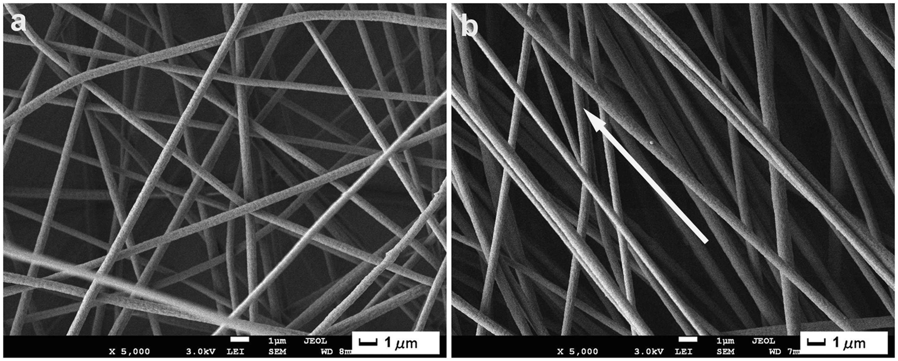
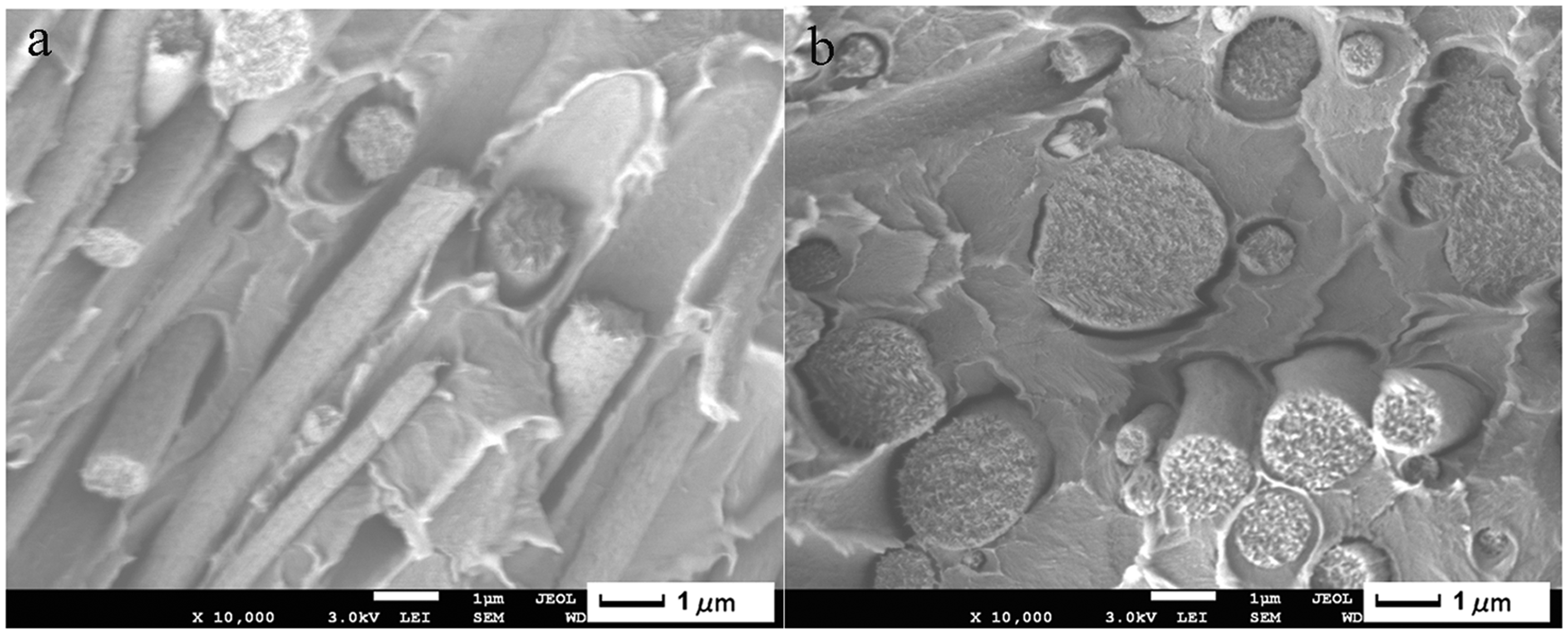
The circular PAN fiber morphology was clearly showed in the cross-sectional SEM images (Figure 2). Compared to the original fibers, the broken fiber surfaces became rougher, and the average diameter of the broken fibers (Figure 2(a)) was ∼660 nm, which was ca. 110 nm larger than the original size of ∼550 nm, suggesting that a PMMA layer was intimately coated on the PAN fiber surface. The surface free energy of PAN (47.7 dynes/cm) is larger than the surface tension of PMMA/cyclohexanone solution (34.0 dynes/cm). 23 Thus PMMA/cyclohexanone solution can wet the PAN fiber. Then the London dispersion and polar forces facilitate the adhesion of PMMA matrix onto PAN fibers.
Mechanical properties of composite films
The reinforcing ability of electrospun nanofibers is generally not impressive, as demonstrated by many researchers. For instance, the addition of 5% electrospun Nylon-6 nanofibers into dental methacrylate of BIS-GMA/TEGDMA (50/50, mass ratio) improved flexural strength by 36%, and elastic modulus by 26% over those of the neat resin.
24
The tensile strength of polyvinyl alcohol (PVA) composite film with 10 wt% electrospun cellulose nanofibers was only 6% more than that of neat PVA film.
6
Figure 3 shows the tensile strength and Young’s moduli of PANF/PMMA composite films. In terms of the tensile strength and Young’s modulus, the embedding of PAN nanofibers imparts increasing reinforcing effect to the PMMA matrix with increasing fiber contents. In a uniform strain situation (as in a composite) the fiber and matrix combine to give the overall modulus (E) according to E(comp) = E(fiber)*V + E(matrix)*(1 − V), where V is the fiber volume percent in the composite. As V goes up the stiffer phase (the fiber) dominates the mechanical properties. Compared to neat PMMA film, the tensile strength and Young’s modulus of the r-PANF/PMMA composite film (fiber content: 16%) increased by 31% and 55.5% to 26.5 and 653.2 MPa, respectively. The Young’s modulus of electrospun PAN nanofibers was ∼50 GPa measured by the AFM technique,
25
so theoretically PAN nanofibers may be a good type of reinforcing fibers, and their reinforcing efficiency should be much better than what was shown in the r-PANF/PMMA composite films. However, the length of electrospun nanofibers is up to several hundreds micrometers,
26
hence their reinforcing efficiency is greatly weakened compared to the fiber with a length of centimeters or even meters. Additionally, the PANF/PMMA interface is possible to act as stress concentration sites, resulting in reduction of mechanical properties of the composite films. In the process of cross-head stretching of the composite film strips, we did notice the development of silver craze, which must be related to the presence of stress concentration sites.
(a) Tensile strength and (b) Young’s moduli (E) of PANF/PMMA composite films.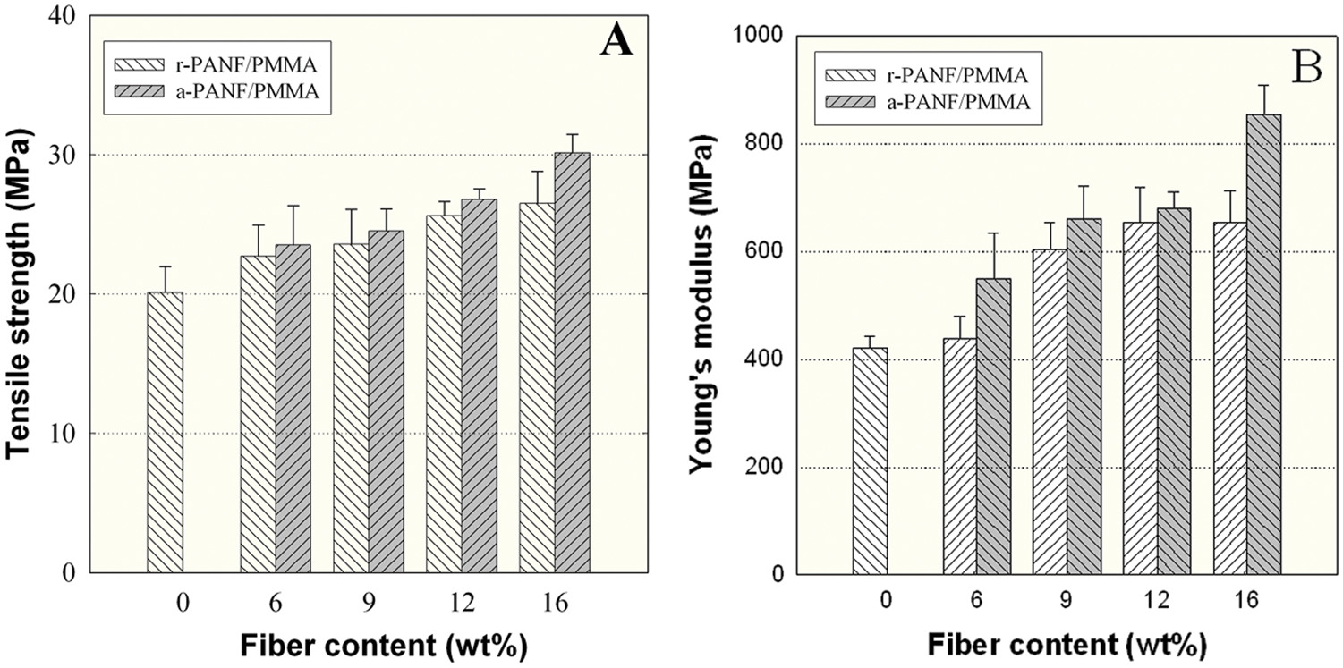
The a-PANF/PMMA composite films with aligned fibers showed stronger mechanical strength and modulus than the corresponding r-PANF/PMMA film with randomly oriented fibers. For a-PANF/PMMA composite film with a 16 wt% fiber loading, its tensile strength and Young’s modulus reached 30.1 ± 1.3 MPa and 853.7 ± 55.0 MPa, respectively. They were respective 40% and 30% more than that of r-PANF/PMMA. With respect to the mechanical property difference between the aligned and randomly organized fiber reinforced composites, this must be associated with the failure behavior under tension, i.e., the break failure of the a-PANF as a bundle creates much stronger mechanical strength than the delamination and slipping failure of the r-PANF. 18
Light transmittance of composite films
PMMA film is an optically transparent material with light transmittance of 92% in the visible light range, but the PAN nanofibrous mat is white in color (Figure 4). After the white PAN nanofibrous mats were impregnated in the PMMA matrix, the composites showed high light transmittance and good transparency (Figure 4(c)). For example, the r-PANF/PMMA composite film with a fiber loading of 16 wt% showed excellent light transmittance of ∼90% (Figure 4(a)), which is only 2% less than that of the neat PMMA film, indicating that the embedded fibers imparted very small loss of transmitted light.
Light transmittance of PANF/PMMA composite films. (a) r-PANF/PMMA, (b) a-PANF/PMMA, (c) digital images of a neat PMMA film and r-PANF/PMMA composite film.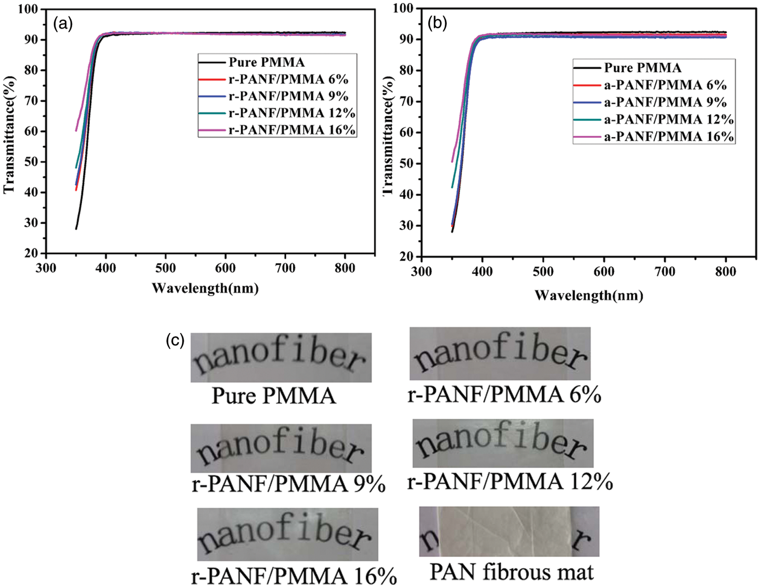
When an incident light reaches an interface, it may reflect, transmit, refract, scatter or absorb. Among them, the light reflection contributes to most of the light loss, and increases with interfacial areas. The amount of light reflection at the interface is highly related to the refractive index of the two materials forming the interface. This relationship is described by the formula: r = [(n1 – n2)/(n1 + n2)]2, where r is the reflective coefficient, and n1 and n2 are RI of the two materials at the interface, respectively. 13 Therefore, the more the difference between the RI of the two materials, the higher the reflective coefficient is. As a result, more amount of light is reflected, and less light is transmitted. The loosely packing and highly porous PAN nanofibrous mat has large amount of air/fiber interfaces. Due to the large RI difference (ca. 0.518) between the air (RI = 1.0) and the fiber, the light is reflected heavily at these interfaces; in addition, it is absorbed in the mat, resulting in big light loss and little light being transmitted through the mats. Thus PAN nanofibrous mat is white in color. In the case of PANF/PMMA composite, the original air/fiber interfaces in the PAN nanofibrous mat are replaced with PMMA matrix/fiber interfaces. The RI difference is small (ca. 0.03), leading to less light reflection but more light transmittance. However, this mismatch to a third decimal place would still cause heavy light scattering at the fiber/resin (PAN/PMMA) interface, 1 thus the conventional PAN fibers (with fiber diameter of several tens micrometer)/PMMA composite films should not be transparent.
The light is actual a type of electromagnetic wave. It may pass an object when its size is less than the light wavelength. Due to the ultrafine diameter (∼550 nm) of electrospun PAN fibers, and intimate coating of PMMA layer onto PAN fibers, the refraction of visible light (wavelength: 400–800 nm) on these fiber/PMMA interfaces is very minor, though the interfacial areas are very large because as much as 16 wt% PAN fibers were used. This results in the production of optically transparent composite films. Due to the nanosize effect, composite films reinforced with bacterial cellulose nanofibers and cellulose nanowhiskers often display very high light transmittance.4,27 The composite films a-PANF/PMMA reinforced with oriented PAN nanofibers were also optically transparent (Figure 4(b)), suggesting that the fiber alignment has little effect on the light transmittance. The appearance of optical transparent r-PANF/PMMA composite films with fiber contents of 6–16% was displayed in Figure 4(c). Letters under the composite films can be visualized clearly, whereas these under PAN nanofibrous mat were invisible.
Thermal mechanical behavior of composite films
The mechanical behavior of PANF/PMMA composite films was analyzed by dynamical mechanical analysis (DMA). From the relationship of tan δ∼temp of a-PANF/PMMA (Figure 5(a)), the glass transition temperature (Tg) of PMMA film was found at 76°C, which is much less than that of commercial atactic PMMAs with a Tg of ∼110°C.
28
This is possibly due to the fact that the PMMA and PANF/PMMA composite films were prepared by solution impregnation method. The residual solvent cyclohexanone (with a boiling point of 156°C) in the films acts as plasticizer, which lowers the Tg of PMMA. Two Tgs were shown for the composite films. The one at ∼72°C was attributable to PMMA matrix. The other one at ∼100°C belonged to PAN fiber. It was kept at almost the same position for composites with varied fiber contents. The relationship of tan δ∼temp of r-PANF/PMMA (not shown) is similar to that of a-PANF/PMMA, showing the fiber orientation in the composites has no different effect on the glass transition behavior.
The tan δ (a) and storage modulus (b) curves of a-PANF/PMMA composite films.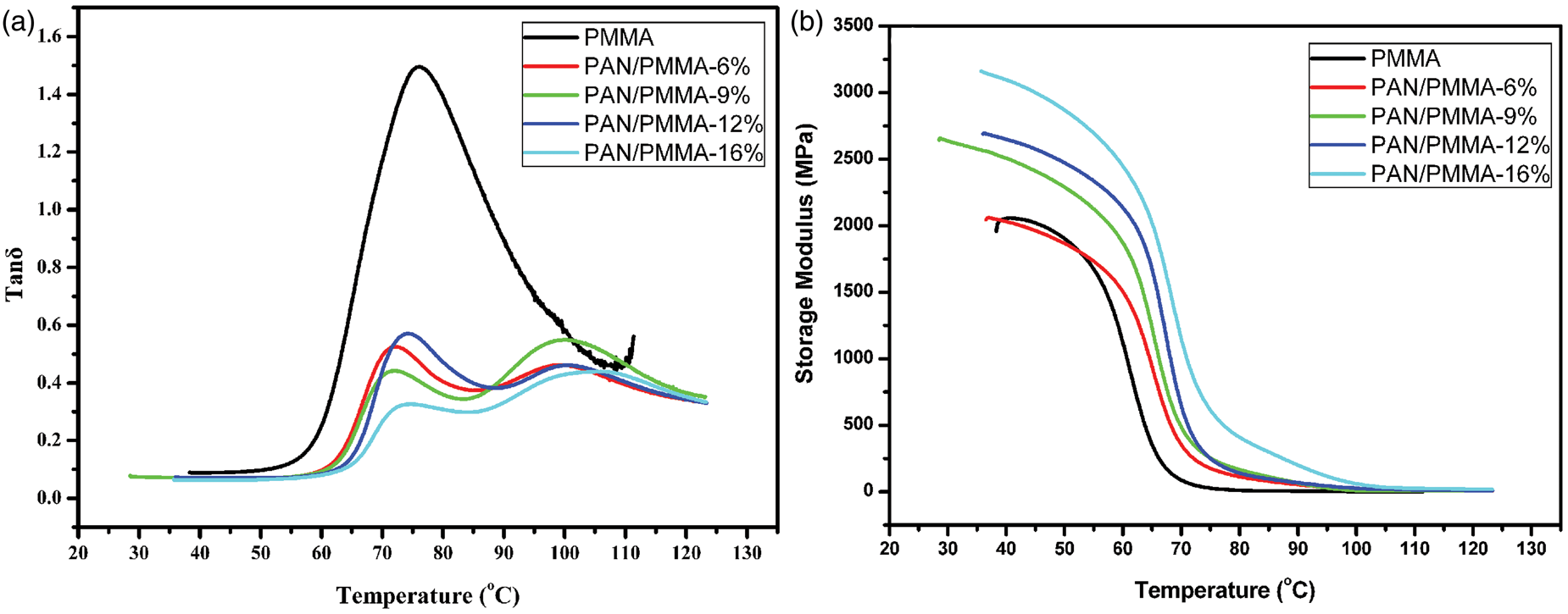
Figure 5(b) shows the storage modulus (E′) of a-PANF/PMMA composite films as a function of temperature and fiber contents. The neat PMMA film showed a typical mechanical behavior of an amorphous polymer material. Its storage modulus E′ at 40°C in the glassy state was 2.04 GPa. It quickly dropped at ∼54°C, where the PMMA chain segments started to relax and underwent glass–rubber transition. With an increasing of temperature to 65°C in the glass–rubber transition state, the E′ substantially fell to 0.36 GPa, which was just 17.6% of the E′ at 40°C. For the a-PANF/PMMA composite film with a fiber content of 6 wt%, its storage modulus at 40°C was almost similar to that of neat PMMA film, but it increased with fiber contents in the range of 9–16 wt%. For instance, the E′ of a-PANF/PMMA-16% was 3.10 GPa, which was 1.55 times more than that of the neat PMMA film, suggesting that PAN fibers can effectively enhance the stiffness in the glassy state. Compared to the E′ (0.36 GPa) of the neat PMMA film at 65°C in the glass–rubber state, the E′s of the composite films a-PANF/PMMA-9% and -16% greatly increased to 1.25 GPa and 2.03 GPa, respectively. In the composites, PAN fibers impart mechanical limitation to the matrix and reduce its mobility and deformation thereby enhancing the storage modulus above Tg. In the temperature zone over 100°C where both PMMA matrix and PAN fiber were in the rubber state, the E′ of composite films reached a platform, same to that of the neat PMMA. The fiber orientation showed a positive effect on the stiffness of PANF/PMMA composite films. In the fiber axis direction, the storage moduli of a-PANF/PMMA were larger than that of r-PANF/PMMA, in both the glassy state (40°C) and glass–rubber transition state (60°C) (Figure 6).
Storage moduli of PANF/PMMA composite films as a function of fiber content at (a) 40°C and (b) 65°C.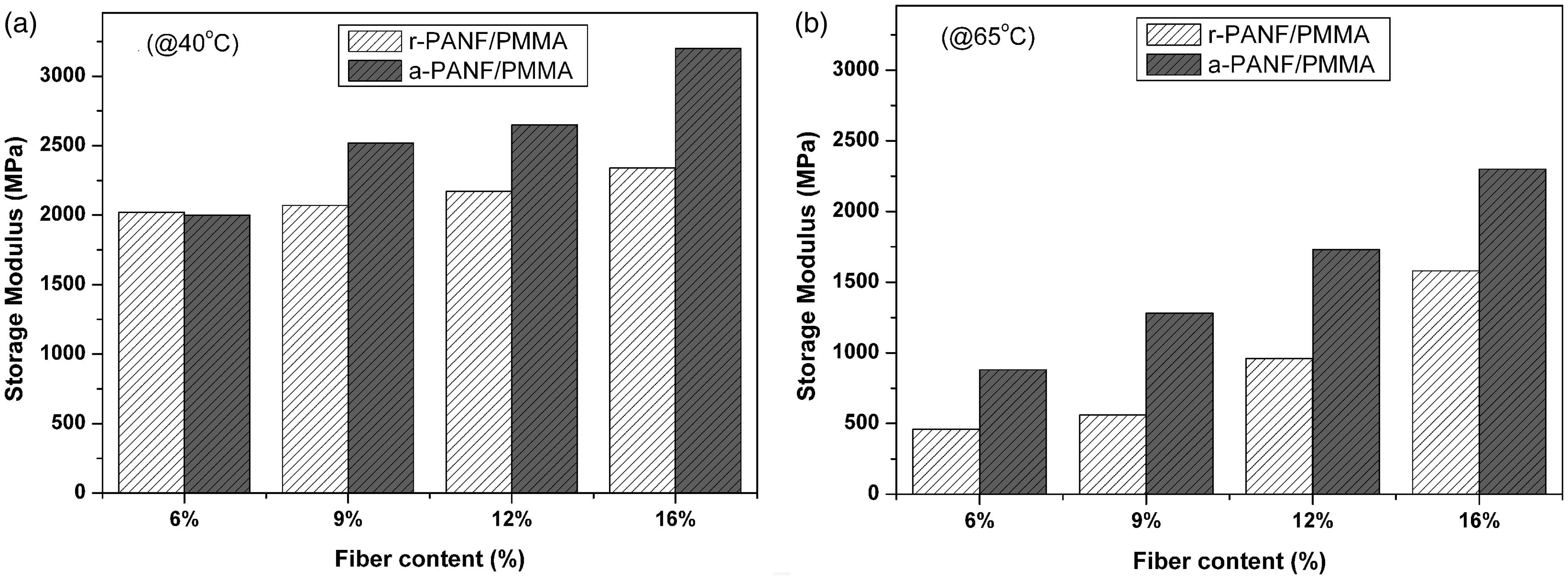
Conclusion
The solution impregnation technique was used to develop PAN nanofibers reinforced PMMA transparent composites. Regardless of the fiber orientation, the light transmittance of PANF/PMMA composite films with fiber content of 6–16 wt% was very close to that of neat PMMA film, and surprisingly reached ∼90% in the visible light range, though the embedded PAN nanofibrous mats were white in color, large fiber/PMMA interfacial areas and different refractive index between PAN and PMMA. The reinforcing efficiency of PAN nanofibers was steadily increased with the fiber loading. The aligned PAN nanofibers were more effective as reinforcing fibers for PMMA matrix. For instance, the tensile strength and Young’s modulus of the film containing 16 wt% aligned fibers were respective 1.4 and 1.3 times more than that with same amount of randomly organized fibers. DMA measurements proved that the embedded PAN nanofibers did not affect the Tg of PMMA matrix, but it substantially increased the stiffness of the matrix in the glassy and glass–rubber transition states.
Footnotes
Funding
This research received no specific grant from any funding agency in the public, commercial, or not-for-profit sectors.
Acknowledgment
This work is supported by the National Natural Science Foundation of China (No. 50973019), the National Basic Research Program of China (2010CB732203), the Natural Science Foundation of Fujian Province (2010J06017).
Conflict of interests
None declared.