
Abstract
The use of woven textile reinforcements in composite structures increased significantly in the past decades due to their interesting properties over unidirectional fibres. Therefore, the prediction of the thermo-mechanical properties of woven fabric composites is essential from a design and manufacturing standpoint. A micromechanical approach based on finite element method that utilizes three-dimensional unit cell was applied to predict the effective properties of a periodic woven fabric composite material. Using the resin processing properties models such as cure kinetics, shrinkage, glass transition temperature and elastic modulus models, the development of the periodic woven fabric composite material thermo-mechanical properties, as the cure progresses was predicted. The residual strains and stresses generated in the composite unit cell during the cure were also predicted and linked with the development of the material properties. The effective properties of the cured woven fabric composite material were compared to the one of an equivalent cross-ply composite material to verify the validity of neglecting the fibre waviness while modelling woven fabric composite.
Introduction
The use of woven textile reinforcements increased significantly in the past decades, especially for liquid composite moulding process, such as resin transfer moulding (RTM). Woven reinforcements have higher drapability and better impact resistance than unidirectional fibres that qualify them as good candidates to manufacture complex structures. The prediction of the thermo-mechanical properties of woven fabric composites is therefore important for the design and the manufacturing of composite parts using woven fabric. Various studies have been carried out to investigate analytically and numerically the thermo-mechanical properties of fabric reinforcements.
Ishikawa and Chou1–5 developed three analytical models to predict the stiffness and coefficient of thermal expansion of woven fabric composites: the mosaic model, the crimp model and the bridging model. The mosaic model described the fabric as an assemblage of asymmetrical cross-ply laminates with no fibre undulation and gave good predictions for fabrics with few interlaced regions, such as satin fabric. The crimp model accounted for the fibre undulation using shape functions was more suitable for plain weave composites. Finally, the bridging model was developed for satin woven fabrics in order to describe the difference in properties between the straight threads region and the interlaced regions. However, these models only considered the undulation in one direction and restrict the two-dimensional (2D) woven structure to one dimension. Naik and Shembekar,6,7 Shembekar and Naik, 8 Ganesh and Naik 9 and Naik and Ganesh10,11 developed a 2D woven fabric model to predict the elastic properties and the coefficients of thermal expansion (CTE) of plain weave reinforced composites at the ply and laminate level. The fibre architecture geometry in the ply, as well as the positions of the different plies in the laminate, with respect to each other, were considered. Their results demonstrated that the elastic moduli were affected by the undulation length, the ply thickness, the gap between two adjacent tows and the laminate configuration. The elastic moduli increased with an increase in the undulated length and a decrease in the ply thickness. Depending on the fibre architecture and the material system, an optimum gap could be determined to improve the elastic properties of the woven composite. Overall, the authors determined that in the case of plain weave woven fabric, higher fibre volume fraction and lesser crimp gave lower CTE and Poisson’s ratio but higher Young’s and shear’s moduli. Their analytical results were then experimentally confirmed. 12 Hahn and Pandey 13 developed a micromechanics model including the fibre architecture parameters to predict the thermoelastic properties of plain weave woven composite. In that case, the fibre undulation was taken into account by the use of geometry efficiency factors. More recently, finite element analyses (FEA) were used to determine the mechanical properties of woven composites. The advantage of FEA is that it also gives information on the internal strains, stresses and displacements generated in the woven fabric. Using homogenization theory, the FEA to calculate the effective properties of a periodic woven fabric composite material is reduced to the behaviour of a small unit cell.14,15 To satisfy the equivalence of elastic energies at the unit cell level and composite material level, periodic boundary conditions are then applied to the unit cell so that it represents the periodic woven fabric composite material.16–21 Glaessgen et al. 22 developed a unit cell model to study the internal displacements, strains and stresses in plain weave composite under axial load. Dasgupta and Bhandarkar 23 investigated the influence of the fibre volume fraction on thermo-mechanical properties of plain weave composite using three-dimensional (3D) unit cell model. Their results showed that the stiffness increased with the fibre volume fraction whereas, the CTE and the Poisson’s ratio decreased. This is in agreement with the experimental study. 12 Finally, the unit cell representation of woven composite was also used in the analysis and prediction of process-induced stresses and deformation.24–26 For this last purpose, Svanberg et al. 27 used a ‘knock down factor’ as an alternative method to reduce the fibre longitudinal modulus and compensate for the fibre weave.
In this study, thermo-mechanical properties of a periodic 5-harness satin (5HS) woven fabric composite material were investigated using a micromechanical approach based on finite element method that utilizes a 3D unit cell. The thermo-mechanical properties examined includes the effective stiffness properties and the CTE. The study objectives were: (i) to characterize thermo-mechanical properties of a periodic 5HS woven fabric composite material; (ii) to investigate the effect of fibre waviness on the cured composite properties and (iii) to compute and study the development of the composite properties and the residual stress as the cure progresses.
Finite element model
5HS woven fabric composite material unit cell
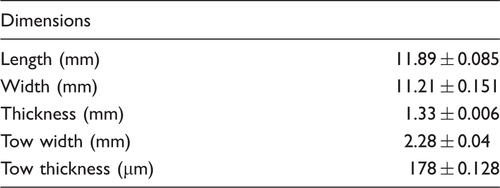
The 5HS woven composite unit cell was developed based on the geometrical parameters of a four plies laminate unit cell, manufactured by RTM with the G30-500-6 k 5HS carbon fibre and the CYCOM 890RTM epoxy. The unit cell length, width and thickness were measured using a digital calliper. The cross-section was observed under an optical microscope with the magnification ×50, as shown in Figure 1, in order to obtain the tow dimensions. The width and thickness of the tow were measured along the cross-section and averaged. The measured unit cell dimensions are reported in Table 1.
(a) Cross-section of four plies laminate, G30-500-6 k carbon fibre/CYCOM 890RTM epoxy resin, observed by optical microscope (×50) and (b) detail of a tow. Measured dimensions of a 5HS unit cell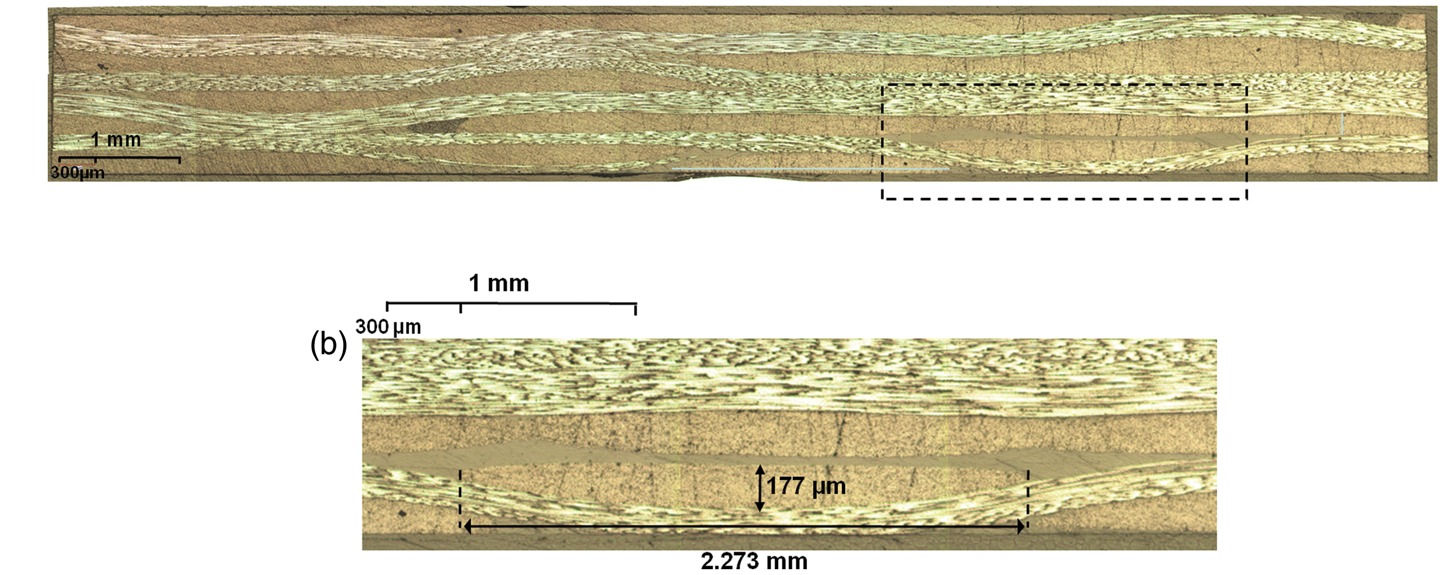
From these observations, the 5HS architecture was then created using TexGen,
28
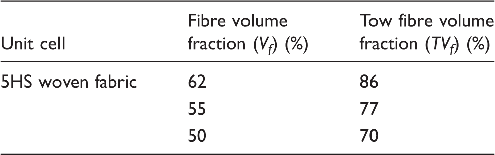
a software dedicated to the modelling of textile structure in 3D, with the following overall dimensions 12 × 12 × 0.36 mm3. Because of the 5HS pattern, five tows with a 170 -µm thickness were positioned along the width and the length with a 0.05-mm gap in between the adjacent tow. This led to a tow with a 2.35-mm width. Three fibre volume fractions (50%, 55% and 62%) in the range of typical fibre volume fraction for the RTM process, were investigated. Based on the volumes generated by TexGen, the fibre volume fraction of the tow (TVf) was estimated for each desired Vf using the following relationship
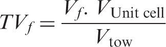
Table 2 presents the three analysed unit cell fibre volume fractions and their corresponding tow fibre volume fractions. The fibre arrangement in the tows was assumed to follow a hexagonal packing configuration. The unit cell volumes were then imported and meshed in finite element software (ABAQUS). The mesh and the dimensions of the final unit cell are presented in Figure 2. Two material sections were defined for the resin and the fibres. Two local rectangular coordinate systems, (x, y, z) and (x′, y′, z′), were created in order to identify the fibre orientations. To account for the fibre waviness, these local systems were defined using the local numbering of each element, so that the out-of-plane axes remained always normal to the element surface, as shown in Figure 2(c). 11872 3D solid 8-nodes linear brick elements (C3D8) were used to mesh the geometry. Finally, a perfect bonding between the fibre and the resin was assumed in the unit cell model.
5HS unit cell: (a) unit cell finite element model and dimensions, (b) tow dimensions, and (c) schematic representation of the fibre orientation along a tow. Unit cell and tow fibre volume fractions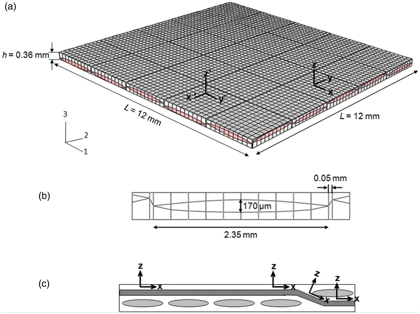
Periodic constraints
The unit cell is a periodic unit representative of the periodic woven fabric composite material. In other word, the woven fabric composite material can be illustrated by a periodical array of unit cell. Therefore, to apply the homogenization theory, continuity in displacement must be satisfied at the unit cell boundaries to ensure that the adjacent unit cells cannot be separated or superposed.16–21 This means that the opposite faces of the unit cell should identically deform and remain parallel to each other to maintain the periodicity for any loading conditions. In order to fulfill this condition, periodic constraints were applied on the nodes of the opposite faces. This required first that the number of nodes on opposite faces and their distribution were identical. Then, constraint equations were applied in term of displacements on each pair of nodes to ensure the periodicity in the three global directions.
In the following, ui represents the displacement in the ith-direction (i = 1, 2, 3), Fj the nodes on the face j, excluding the edges and corners nodes, Ekl the nodes located on the edge sharing the faces k and l, excluding the corners nodes, and finally, Njkl the corner node sharing the faces j, k and l. The described notations are illustrated in Figure 3.
Unit cell faces, edges and corners notations.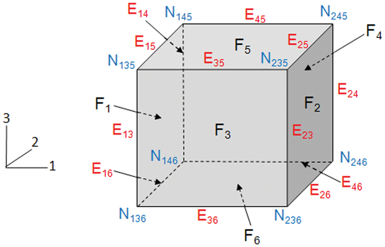
The periodic constraint equations for the opposite faces were defined as follows
16


These equations ensure that the opposite faces F1 and F2, F3 and F4, F5 and F6 remain parallel for any loading conditions. Similarly, periodic constraints on the opposite edges were expressed in the following manner
16


Loading conditions
Each model was loaded under seven different conditions: three axial strains, three shear strains and one temperature change to determine the nine engineering constants and the CTE in the three directions. The average axial and shear strains were applied through fixed displacements on the corner nodes of the unit cell.
To apply average axial stains on the unit cell, normal displacements ui were applied to each corner nodes of the faces F2, F4 and F5, while the opposite faces F1, F3 and F6 were fixed in the three directions, respectively. For example, in the 1-direction, the corner nodes of F1 are fixed in the three directions, while identical displacements u1 were applied at each nodes of F2 in the 1-direction. The displacement of the corner nodes of F2 was also prevented in the directions 2 and 3 as shown in Figure 4(a). These axial loadings enable the determination of the three effective elastic moduli E1, E2 and E3 and the Poisson’s ratio ν12, ν13 and ν23.
Boundary conditions: (a) for an axial loading, (b) for a shear loading and (c) for a thermal loading.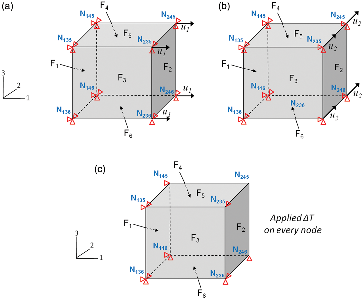
The average shear strains were simulated by applying tangential displacements uj to each corner nodes of the faces F2, F4 and F5, while the opposite faces F1, F3 and F6 were constrained in the three directions. For example, for the shear load in the 1–2 direction, the corner nodes of F1 were fixed in the three directions, and the corner nodes of F2 were subjected to a displacement u2 in the 2-direction. The corner nodes of F2 were also constraint in the directions 1 and 3 as shown in Figure 4(b). These shear loads allow the determination of the effective shear moduli G12, G13 and G23.
Finally, an increase in temperature from 25°C to 150°C was applied to the unit cell models in order to determine the CTE in the three global directions. The corner nodes of each face of the unit cell were fixed in the directions 1, 2 and 3 to prevent any deformation as shown in Figure 4(c).
The periodic constraints and the loading conditions were verified by simulating the properties of unidirectional and cross-ply configurations. Typical properties of T-300 carbon fibre and epoxy resin were implemented in the model and the obtained engineering constants were compared to the one available in the literature. 12 A maximum of 5% difference was observed, validating the periodic constraints and the loading conditions employed.
Methodology
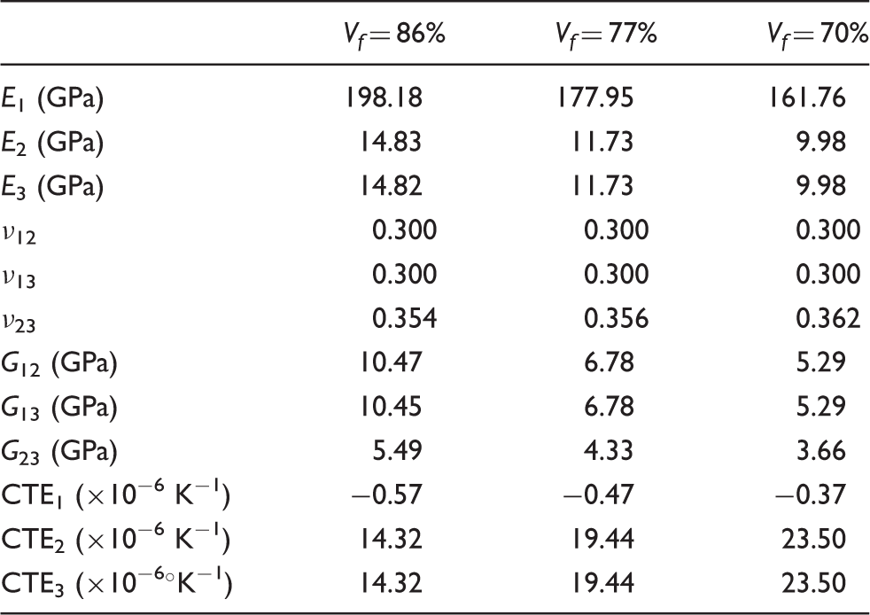
The following methodology was then used to determine the thermo-mechanical properties of the 5HS woven fabric composite material as shown in Figure 5. The thermo-mechanical properties of the tow were first determined using a unit cell with a fibre hexagonal packing configuration. The epoxy resin was considered isotropic and the carbon fibres orthotropic. The three tow fibre volume fractions, 70%, 77% and 86% were investigated. Then, these computed tow properties were used as input for the tow properties into the 5HS woven unit cells at 50%, 55% and 62% fibre volume fractions, respectively. In addition, the thermo-mechanical properties of the 5HS woven fabric composite material unit cell were compared with the properties of equivalent unit cells with two unidirectional plies with a [0/90] stacking sequence. These equivalent unidirectional cross-ply unit cells were modelled with the same material system and fibre volume fractions (tow and unit cell) but did not take into account the fibre undulation present in the fabric material. Finally, computed tow properties were used as input to compute the development of the composite properties and the residual stress, as the cure progresses.
Applied methodology to determine the thermo-mechanical properties of the unidirectional cross-ply and 5-harness woven fabric unit cells.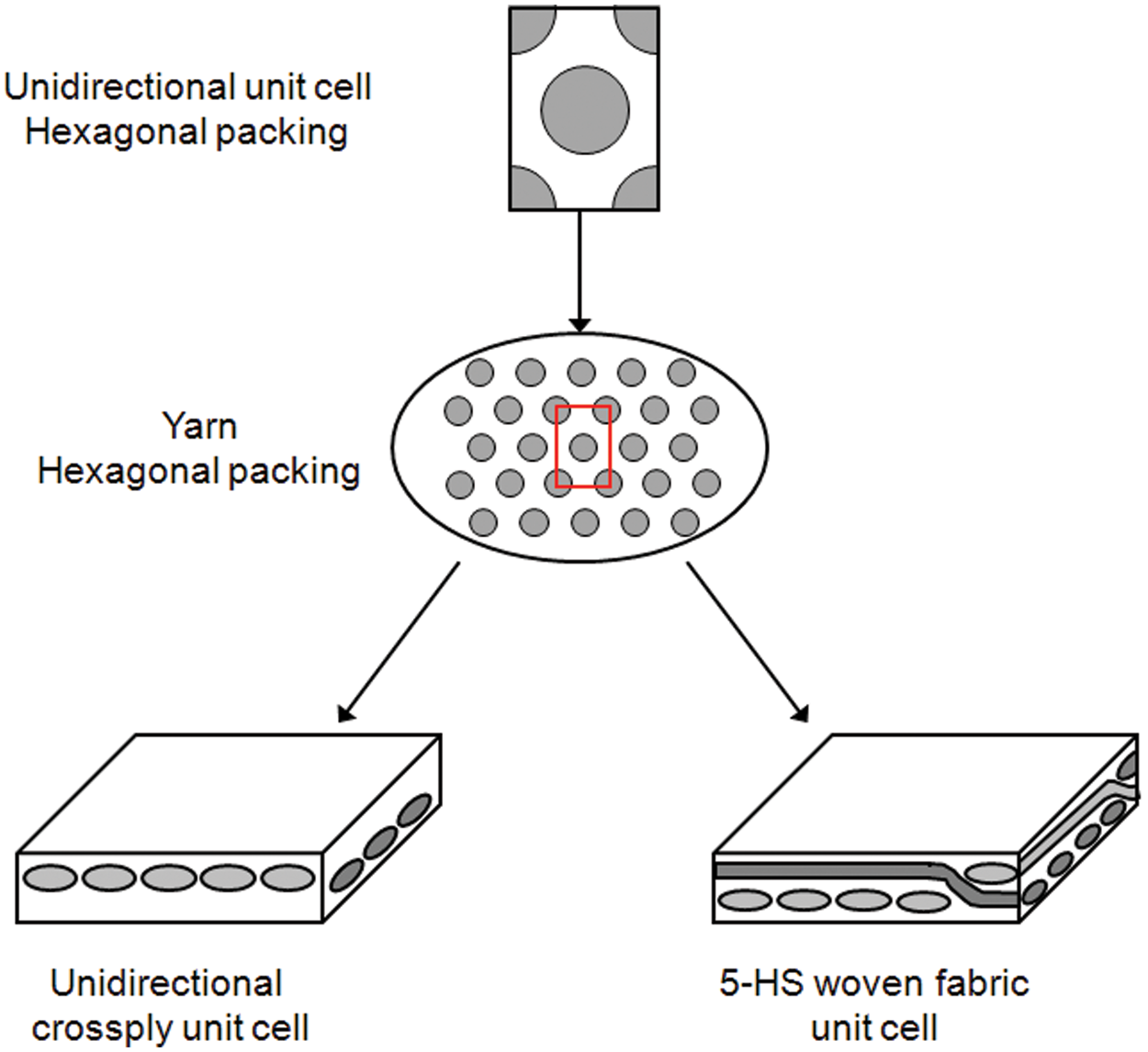
Elastic properties
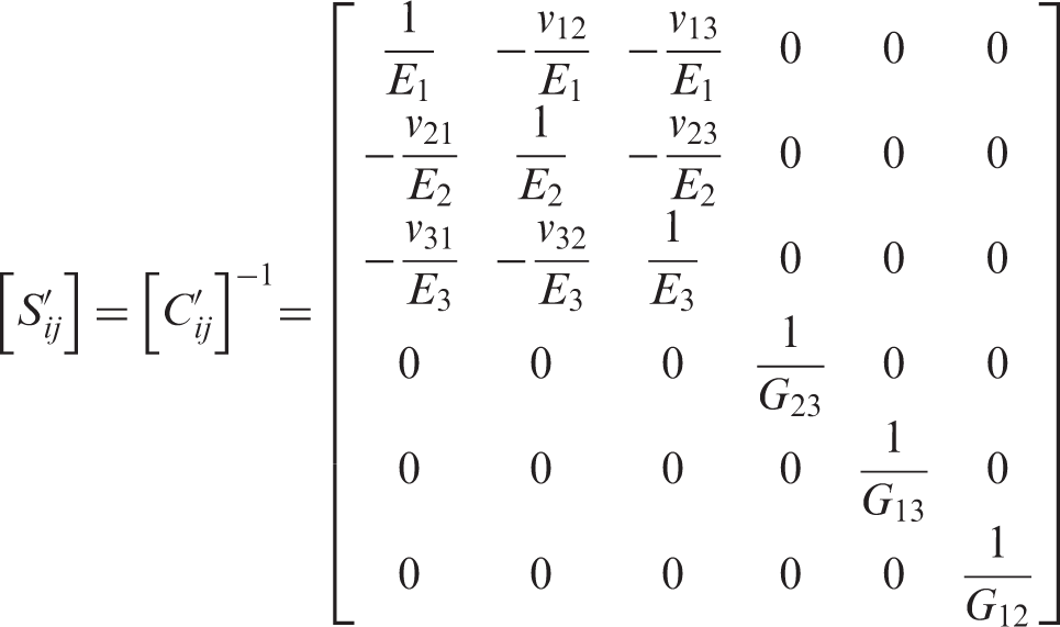
The generalized Hooke’s law for an anisotropic material is given by
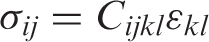
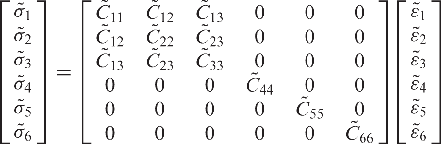
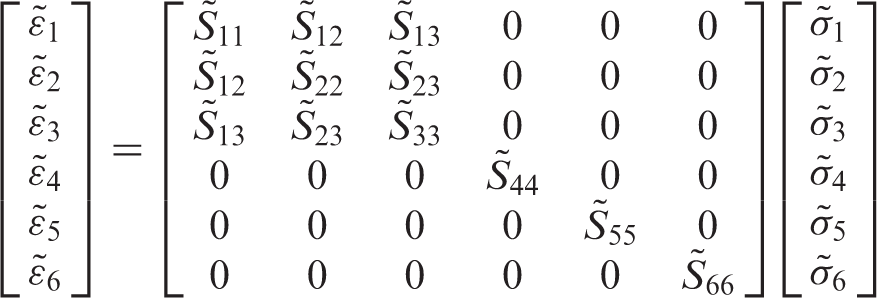
Here, 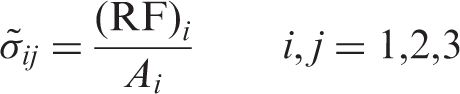
Once all the independent constants of the stiffness matrix were calculated using reaction forces, the stiffness matrix was inversed to obtain the compliance matrix. From the compliance matrix, the elastic moduli, shear moduli and Poisson’s ratio were extracted using equation (18)
Coefficients of thermal expansion
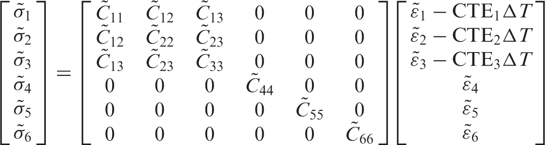
When a material is subjected to a temperature change ΔT, Hooke’s law can be modified as follows
where CTE i is the coefficient of thermal expansion.
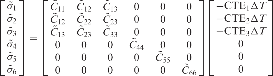
Considering the applied boundary conditions, no deformation was allowed and equation (19) can be reduced to
In this case, the stresses were calculated by integrating the stresses of each element over the volume of the unit cell.
Hexagonal packing configuration
Carbon fibre and epoxy resin thermo-mechanical properties
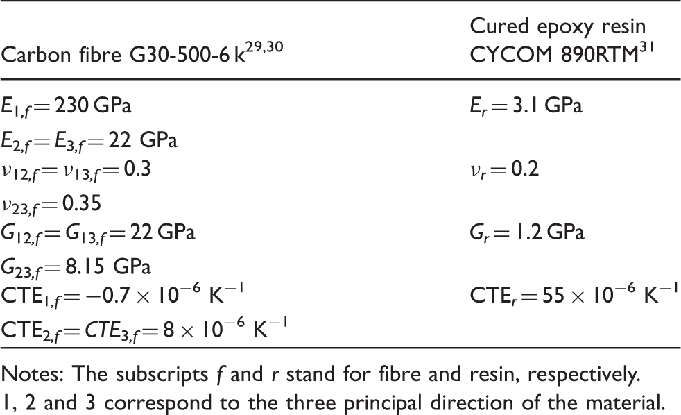
Notes: The subscripts f and r stand for fibre and resin, respectively.
1, 2 and 3 correspond to the three principal direction of the material.
Tow thermo-mechanical properties at different fibre volume fractions
Development of the thermo-mechanical properties during processing
The knowledge of the composite thermo-mechanical properties development during the manufacturing process is important to understand how the residual strains and stresses are generated and how the material properties can affect their development.
Using the finite element software ABAQUS and the COMPRO Common Component Architecture (CCA), 32 a material database including the material constitutive models, the evolution of the composite properties and the development of residual stresses, as the cure progresses, were predicted. Heat transfer analysis was first performed followed by a stress analysis. The resin manufacturer recommended cure cycle (MRCC) was applied in the simulation as temperature field: 2 h at 180°C followed by a cool down to 25°C at 1°C/min. The material constitutive models of the resin (cure kinetics, glass transition temperature, CTE, chemical shrinkage and elastic modulus) developed in a previous study published by the authors 33 were implemented in the COMPRO CCA material database and used as resin properties in the finite element model. With this approach, the resin is modelled as a cure hardening instantaneous linear elastic material during the entire simulation. The initial resin elastic modulus was set to Er = 100 Pa in order to take into account the resin liquid state at low degree-of-cure α and enable the convergence of the numerical simulation. Using the tow properties computed from the hexagonal packing configuration as the fibre properties and the resin properties defined from the constitutive models, the effective properties of the composite at different degree-of-cures were then calculated with the methodology described previously (equations (16) to (19)).
Experimental method
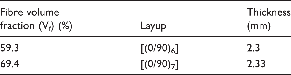
Laminate characteristics
Young’s modulus
The modulus measurements were carried out using the three-point bending test based on ASTM standard D790-03 35 using a MTS Insight 5 kN machine. A constant displacement rate at 6 mm/min was applied to the specimens, based on their geometry while recording the applied load. A span-to-depth ratio of 40 to 1 was used in order to reduce the effect of the shear deflections that can reduce the apparent modulus. Five tests were performed for each fibre volume fraction specimens.
Thermal expansion
The CTEs were measured experimentally by a thermo-mechanical analyser (TMA). TMA tests were carried out to measure the CTE in the three directions. A force of 0.05 N was applied to the probe to ensure a constant contact with the composite sample. Three temperature cycles from room temperature up to 220°C each, then back down to room temperature, at a rate of 3°C/min were performed for each sample. The slope of the displacement–temperature curve corresponds to the material CTE.
Results and discussion
The material properties of the epoxy resin listed in Table 3 were used as input for the resin properties for the finite element models. In those models, the tow fibre arrangement was assumed to be hexagonal, and the tow properties of the unidirectional finite element models, listed in Table 4, were used as input for the fibre properties.
Elastic properties
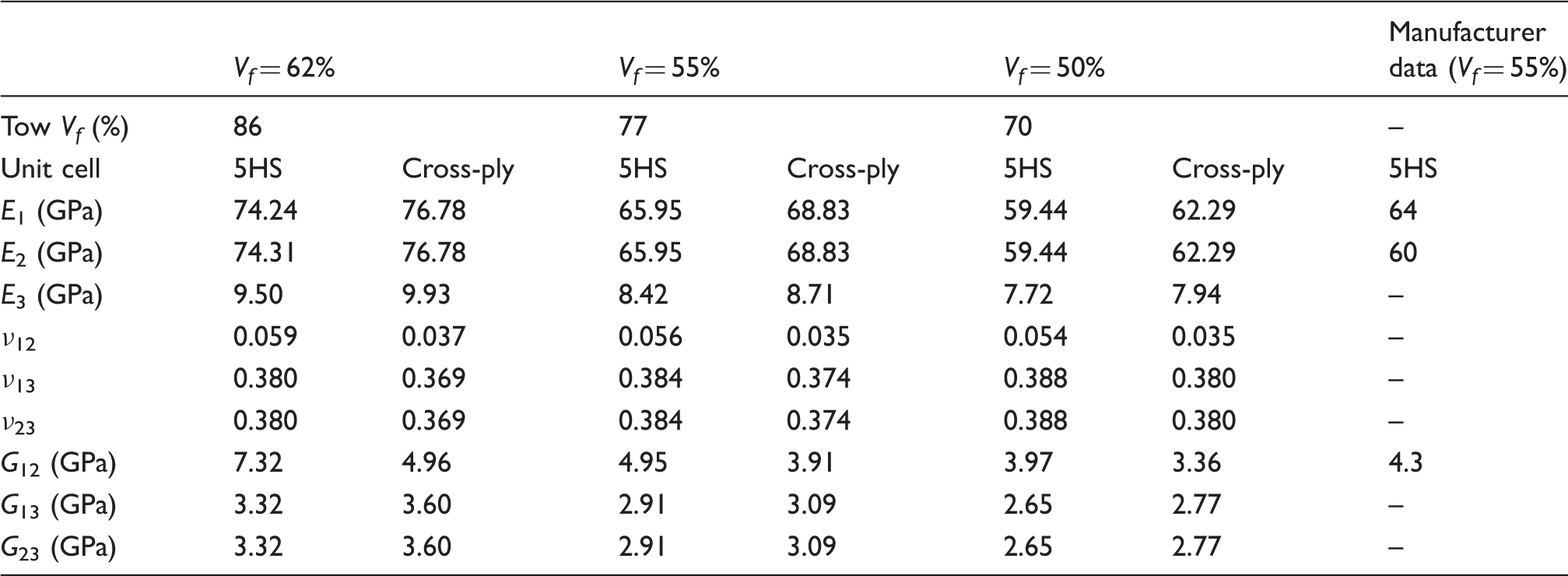
Engineering constants obtained for the 5HS unit cell and the cross-ply unit cell for different fibre volume fractions
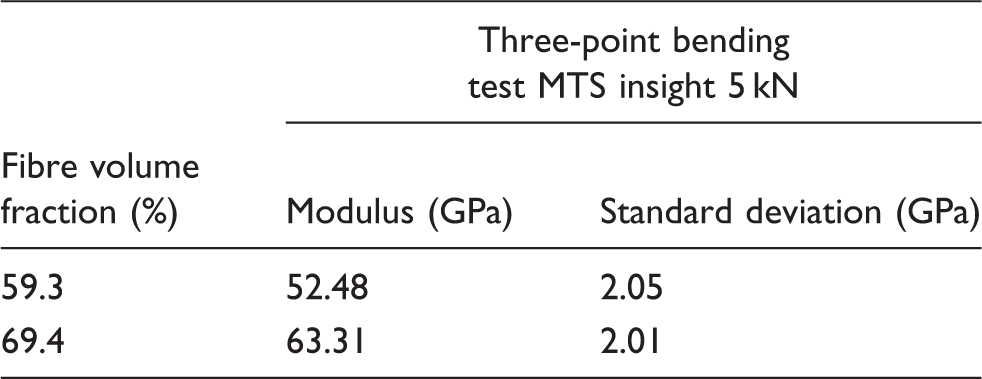
Flexural modulus of the 5HS laminates
From Table 6, it can be noticed that the in-plane elastic moduli, E1 and E2 of the 5HS unit cell are slightly smaller than the one of equivalent unidirectional cross-ply unit cell. This is due to the fibre undulation that reduces the in-plane tow stiffness. No significant difference between the two unit cells was noticed for the through-thickness elastic modulus E3 because of the matrix-dominated behaviour in that direction. On the other hand, the in-plane shear modulus G12 is noticeably higher for the 5HS than for the cross-ply. This behaviour is caused by the tow interlacing in the 5HS woven reinforcement. As for the through-thickness elastic modulus, the out-of-plane shear moduli, G13 and G23, are comparable for the cross-ply and 5HS composites. The in-plane 5HS Poisson’s ratio values, ν12, are higher than those of the corresponding cross-ply laminate at the same volume fraction, again as a result of the fibre undulation. Similarly, the out-of-plane Poisson’s ratio values, ν13 and ν23, are higher for the 5HS composite than the cross-ply unit cell.
The experimental data obtained from the manufacturer for a 55% fibre volume fraction carbon epoxy laminate with the CYCOM 890RTM epoxy resin and a 5HS woven fabric with similar properties to the G30-500-6 k carbon fibre are presented in Table 6. The predictions of the in-plane elastic modulus and in-plane shear modulus are in good agreement with the manufacturer experimental data. However, the small difference between the warp and fill directions is not captured by the FEA. As expected, the experimental flexural moduli are lower than the numerical tensile values (Table 7) due to the development of shear stress in the sample with the three-point bending configuration, leading to a decrease of the apparent modulus, compared to one obtained with a tensile test.
Overall, these results are in agreement with previous experimental and numerical studies on the thermo-mechanical behaviour of plain weave fabric composites by Ganesh and Naik 9 and Naik and Ganesh.10,11 Despite the slightly lower properties of 5HS composites, these results validate the use of equivalent unidirectional cross-ply to model the elastic behaviour of periodic 5HS woven fabric composite material.
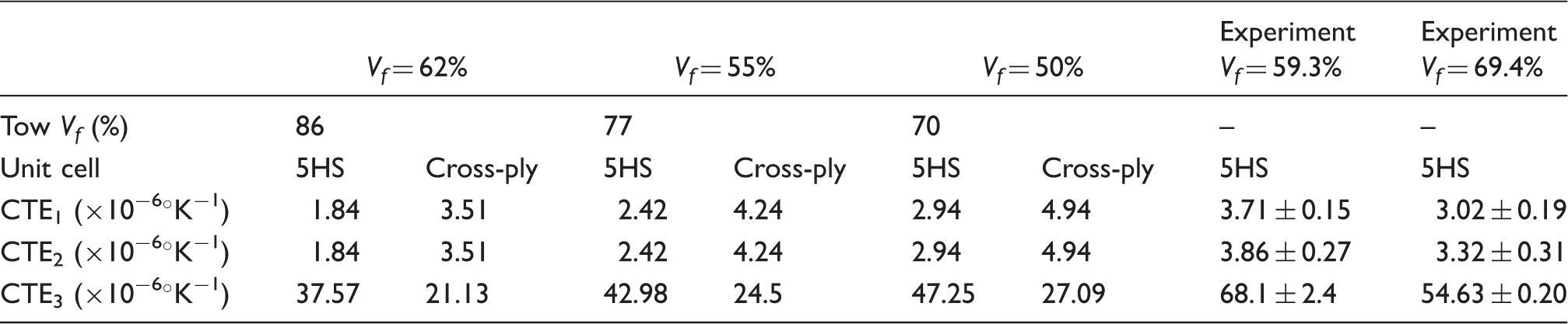
Coefficients of thermal expansion
Numerical CTE obtained for the 5HS unit cell and the cross-ply unit cell for different fibre volume fractions
Development of the thermo-mechanical properties during processing
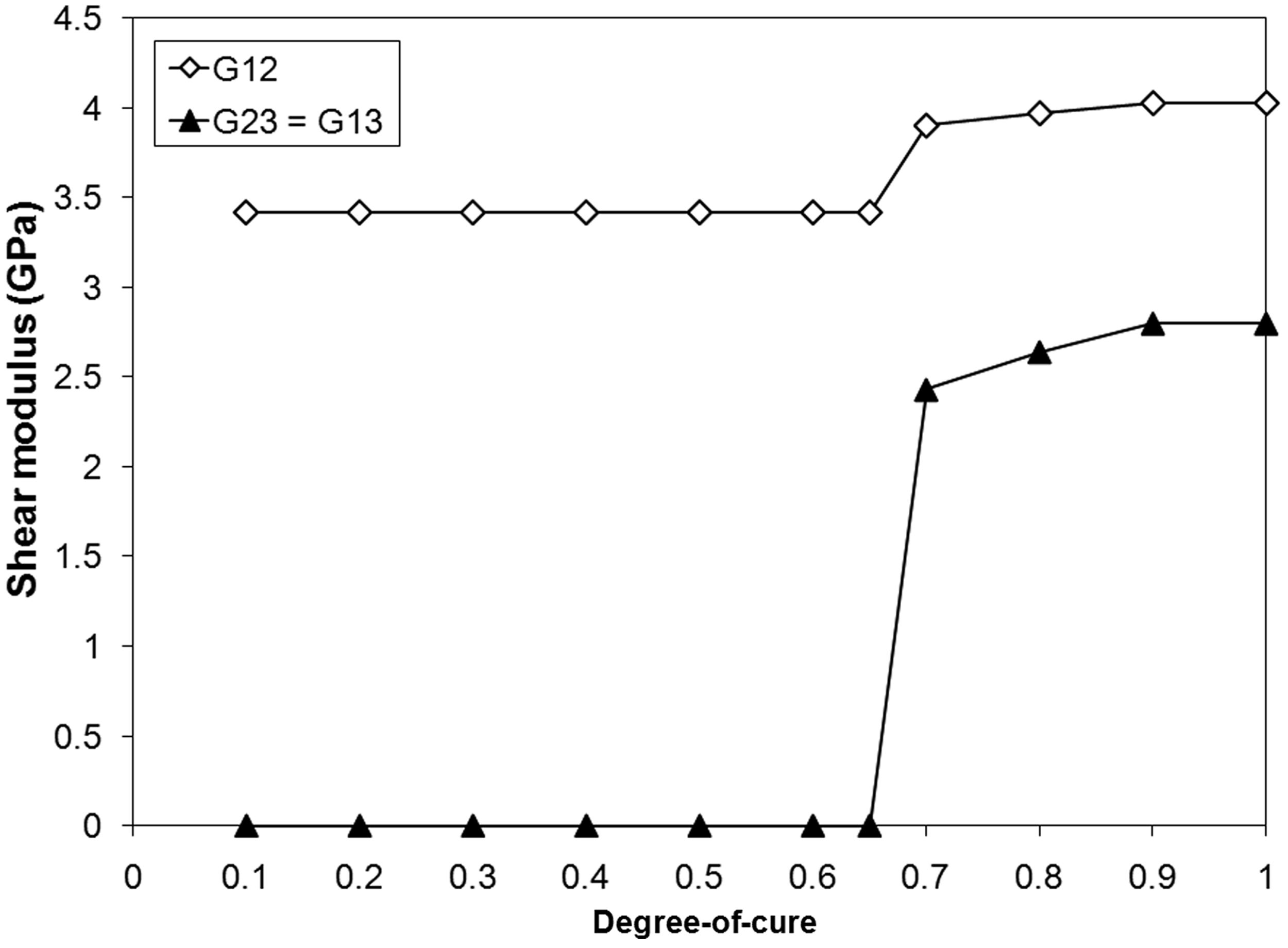
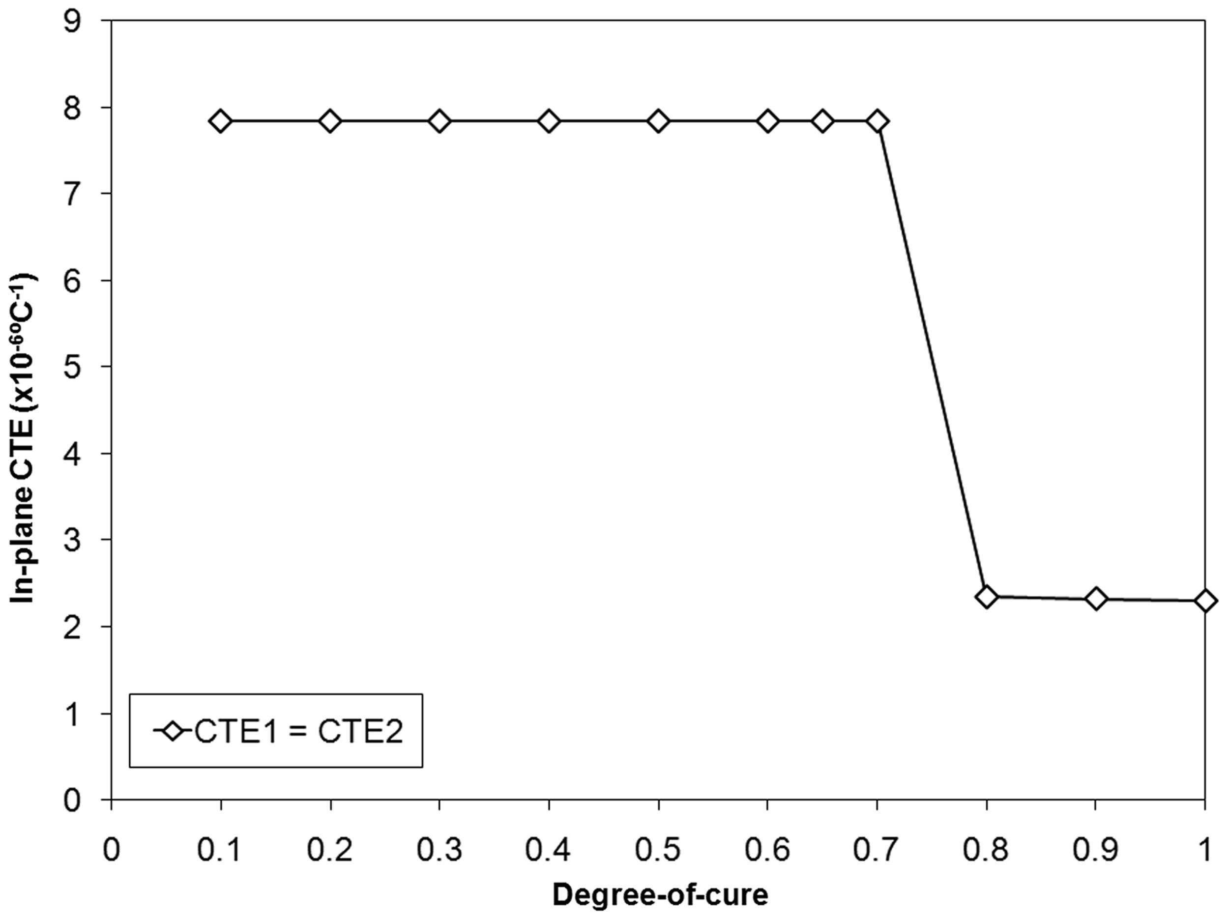
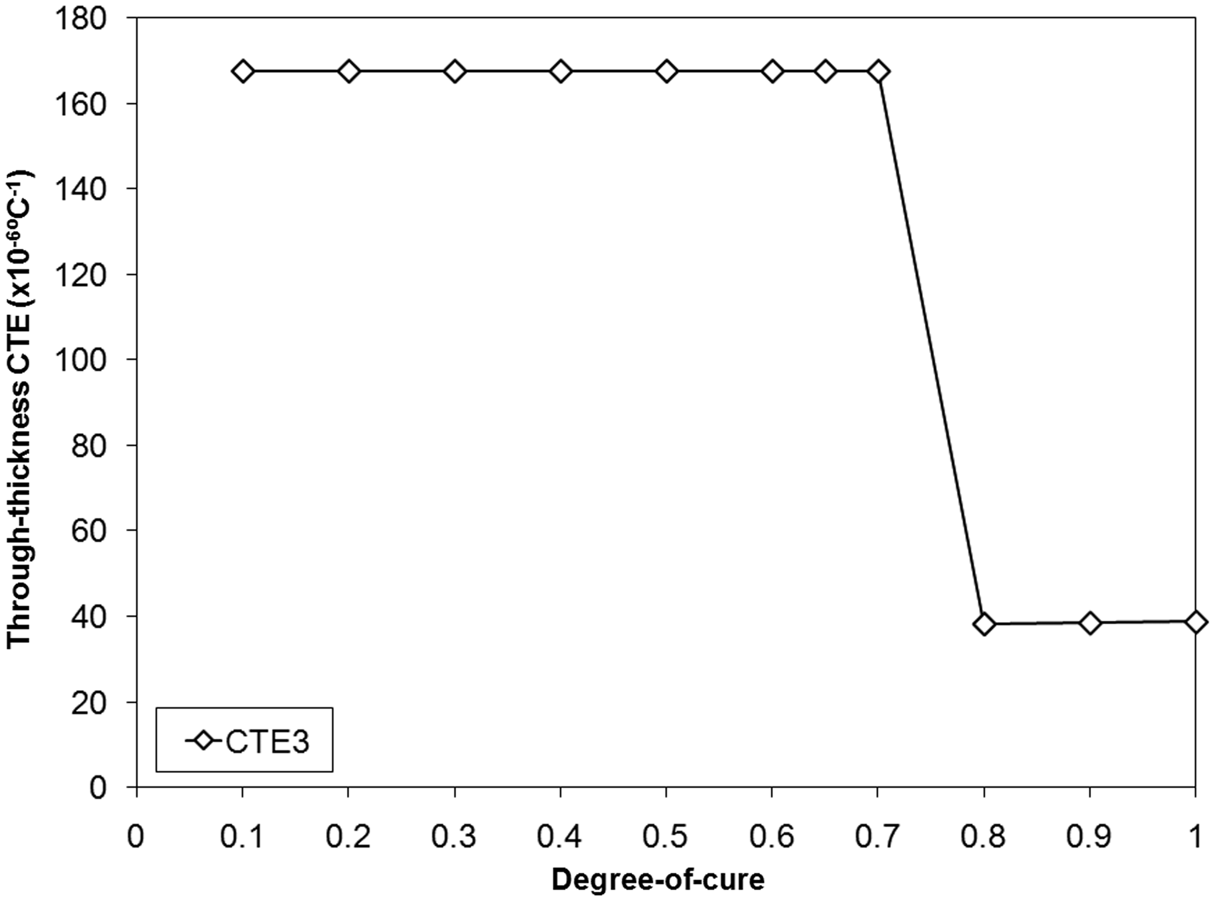
Figures 6 to 9 show the evolution of the thermo-mechanical properties of the 5HS unit cell with the degree-of-cure at a fibre volume fraction of 50%. The gel point can be observed at approximately α = 0.7 with a significant change in the composite thermo-mechanical properties. The elastic properties remained constant before the gel point and kept increasing slightly with the degree-of-cure after the gelation due to the development of the cross-linking network and the resin evolving from a liquid to a rubber state and glassy state. The in-plane and through-thickness CTE significantly decrease after the gelation.
Evolution of the 5HS unit cell elastic modulus with the degree-of-cure. Evolution of the 5HS unit cell shear modulus with the degree-of-cure. Evolution of the 5HS unit cell in-plane CTE with the degree-of-cure. Evolution of the 5HS unit cell through-thickness CTE with the degree-of-cure.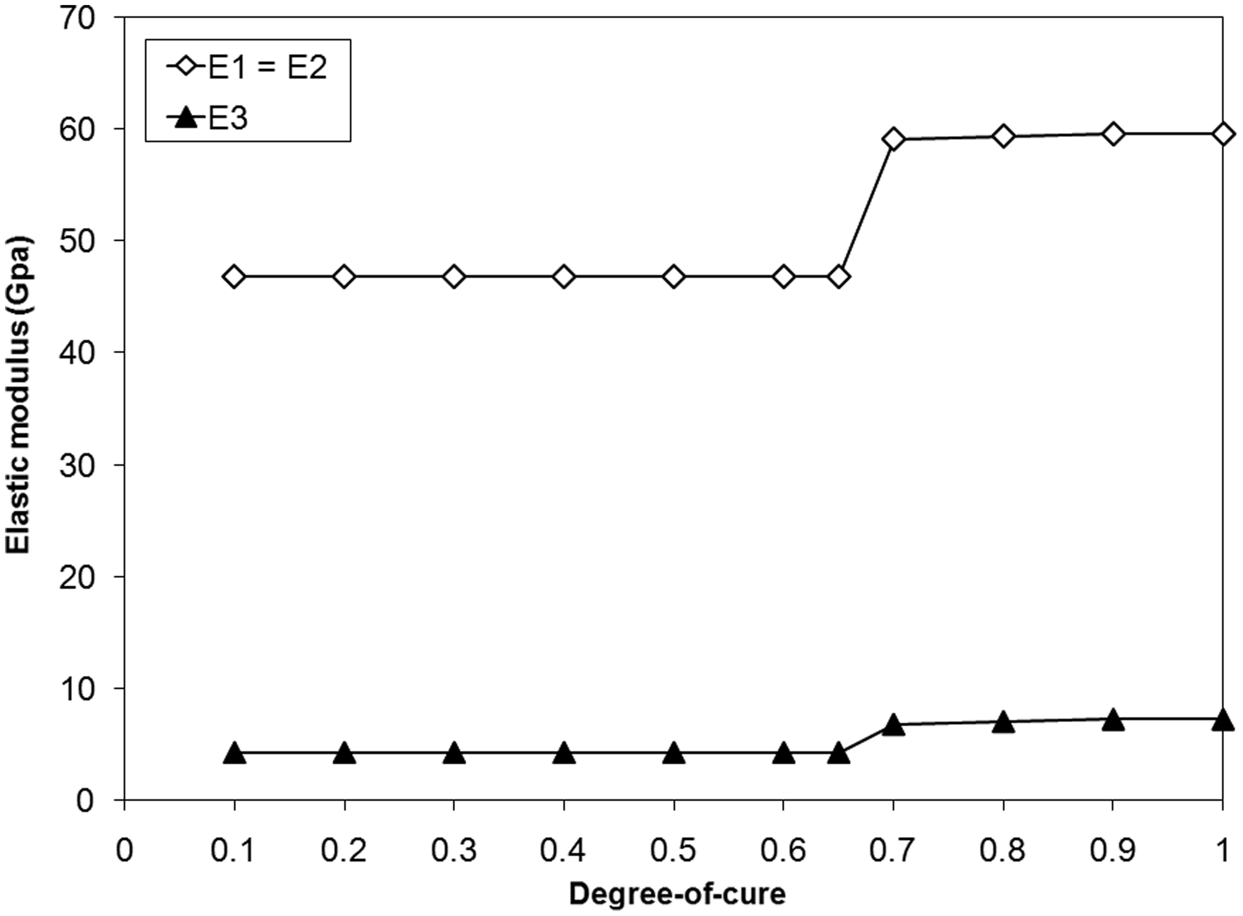
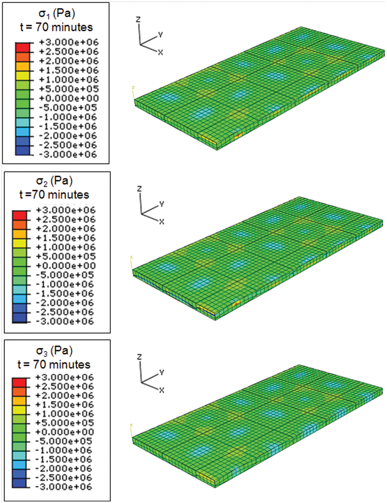
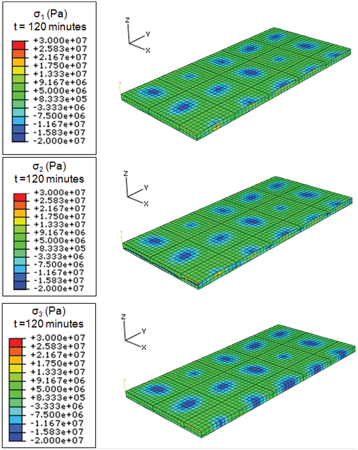
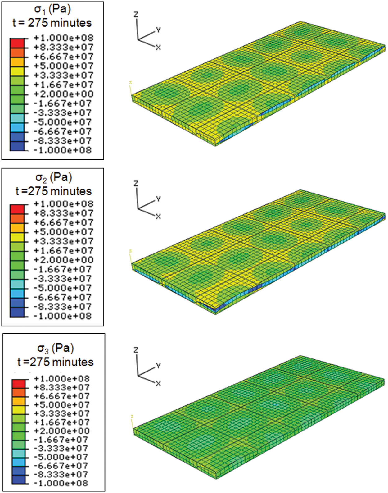
The evolution of the stresses in the 5HS unit cell during the MRCC of the epoxy resin was then predicted. Figure 10 presents the predicted degree-of-cure and glass transition temperature evolution during the MRCC. The gel point occurred at αgel = 0.7 and the gel time at tgel = 69 min. Figures 11 to 13 show the stresses presented in a global coordinates (x−, y−, and z−directions) at different time for a 5HS unit cell with a 50% fibre volume fraction and 70% tow fibre volume fraction. In order to observe the state of stress inside the unit cell, the model was cut in two along the yz plane. Before the gel point, no stresses were present in the unit cell. Small compressive stresses arose after the gel point due to the resin shrinkage at the fibre overlap (Figure 11). The compressive stresses increased during the isotherm with a maximum compressive stress around 20 MPa at the end of the temperature held in the three directions (Figure 12). The maximum compressive stresses are also located where the fibres are overlapping. At the end of the cure cycle, the fibres remained in compression with compressive stresses around 50 to 100 MPa. The resin is in tension in the in-plane direction and in compression in the through-thickness direction (Figure 13). Similar results were obtained for the 55% and 62% fibre volume fraction 5HS unit cell. During the processing of composite part, these stresses generated during the cure cycle combined with the stresses that can arise due to the tool-part interaction can lead to the generation of residual strains, stresses and part distortions as examined in the study of Khoun and Hubert.
37
Predicted degree-of-cure and glass transition temperature for the epoxy MRCC. Stresses in the three directions of a half 5HS unit cell (Vf = 50%) at the gel point (t = 70 min). Stresses in the three directions of a half 5HS unit cell (Vf = 50%) at the end of the isotherm (t = 120 min). Stresses in the three directions of a half 5HS unit cell (Vf = 50%) at the end of the cool down (t = 275 min).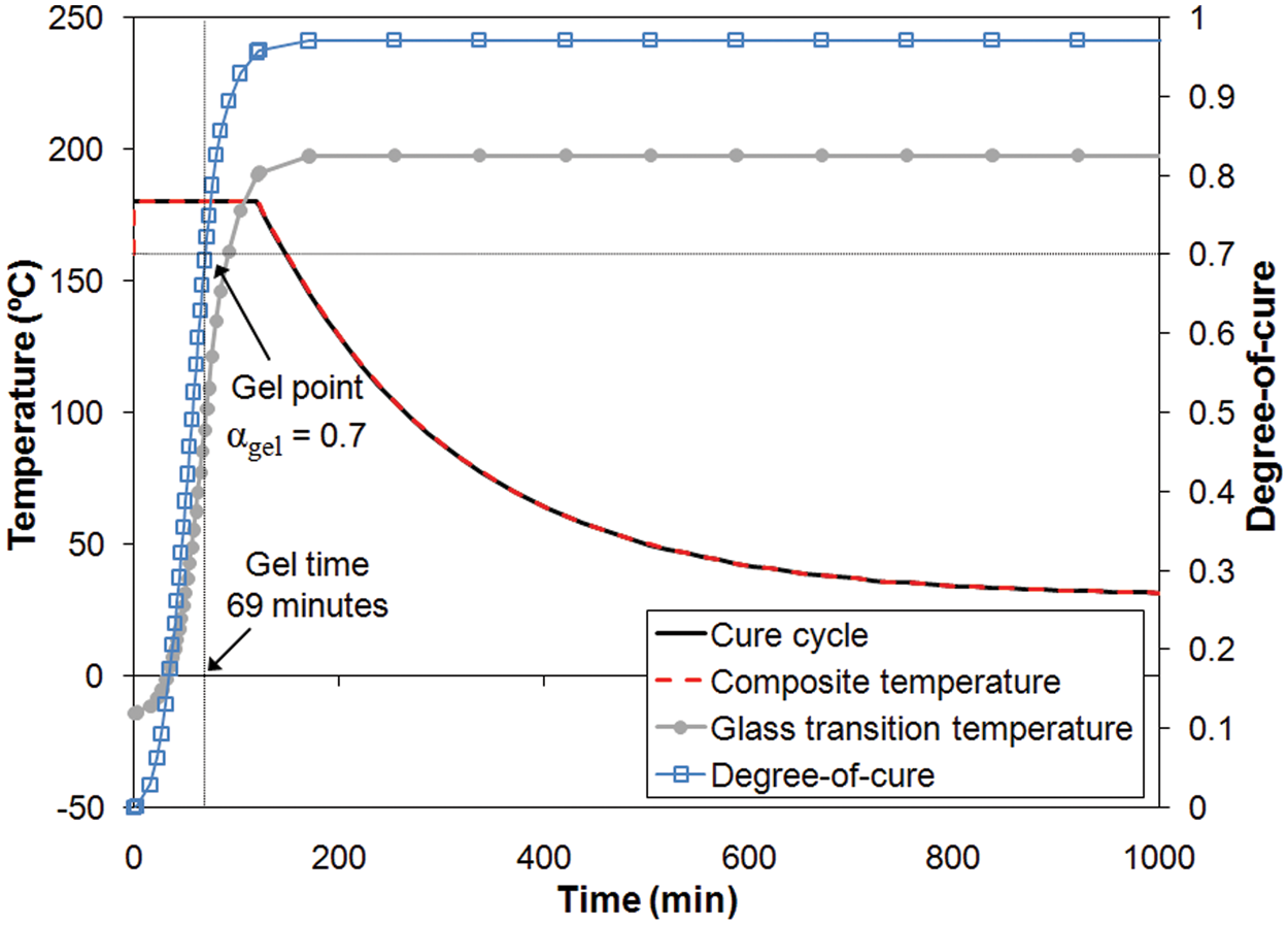
Conclusions
In this study, the thermo-mechanical properties of periodic 5HS woven fabric composite material were investigated and compared to an equivalent unidirectional cross-ply composite using a micromechanical approach. Various fibre volume fractions were investigated corresponding to typical volume fraction used in the RTM process.
Due to the fibre waviness, the in-plane elastic moduli of the 5HS woven fabric composite material are a slightly smaller than a unidirectional cross-ply laminate with the same fibre volume fraction, whereas the in-plane Poisson’s ratio remains higher. The in-plane shear modulus of the 5HS woven fabric composite material is noticeably higher than the cross-ply one because of the tow interlacing effect. Finally, the in-plane CTE of 5HS woven fabric composite material is half the one of the cross-ply laminate, whereas the through-thickness CTE is doubled compared to the cross-ply laminate. All the other properties remain comparable. These results demonstrate that the elastic properties of the 5HS woven fabric composite material and the equivalent unidirectional cross-ply laminate are slightly different but overall comparable. This can validate the use of the properties of unidirectional [0/90] layup to model the elastic behaviour of 5HS woven fabric composite material. When thermal conditions are considered, inaccuracy can be generated due to the difference in CTEs between the 5HS woven fabric composite material and the cross-ply composite. Using the ABAQUS/COMPRO CCA platform, the evolution of the 5HS thermo-mechanical properties with the degree-of-cure was evaluated as well the stresses generated during a typical cure cycle. The prediction of the composite property development during the manufacturing process is essential to understand the effect of the material parameters leading to the generation of residual strains, stresses and part distortions.
Footnotes
Funding
This study was supported by the Consortium for Research and Innovation in Aerospace in Quebec (CRIAQ), the Natural Sciences and Engineering Research Council of Canada (NSERC), Bell Helicopter Textron Canada and Delastek under the grant (CRDPJ 32617-05).
Acknowledgements
The authors thank Tadayoshi Yamanaka for his precious advice and help on the unit cell modelling. They also acknowledge Convergent Manufacturing Technologies Inc. for the licence of COMPRO Convergent Architecture.
Conflict of interest
None declared.