






Abstract
When a continuum approach is considered for textile reinforcements, the internal loads are described by a stress tensor. The mechanical behaviour of the textile material is very much dependent on the fiber directions, and the frames defined from warp and weft directions are preferred to write the stress components. The exterior loads in these frames permit to define tensile and pure shear states. Nevertheless, these frames are generally not orthogonal. The relationships between the exterior loads and the different stress components are analyzed in the present paper, and, in particular, the relationship between direct stress components and longitudinal loads on one hand, and shear stress components and transversal loads on the other hand. When dealing with textile materials, the exterior loads in the direction of the fibres and transverse to the fibres define the pure tensile and pure shear state. It is shown that the covariant stress component matrix is diagonal in a pure tensile loading and that the first mixed direct stress components are equal to zero in a pure shear loading. In these cases, the direct relationship between the stresses and the loadings are given. This is applied to the cases of the picture frame test, the biaxial tensile test or of a combined tension-shear test.
Keywords
Introduction
Liquid composites moulding (LCM) technologies can be combined with dry fibre preform manufacturing technologies.1–3 Textiles need to be draped on a shape that is frequently double curved and requires planar shear deformations of the reinforcement. The draping of this textile preform is often delicate and some software packages have been developed to simulate this forming process and avoid trial-and-error developments.4–13 These simulations and in particular those that are based on the finite element method require the knowledge and a model of the mechanical behaviour of textile reinforcements during forming.
Textile materials are made of fibres often gathered in yarns that are woven, braided and stitched. The resulting mechanical behaviours are therefore specific. They are strongly anisotropic and above all some relative sliding is possible between fibres and yarns. Some stiffnesses are substantially reduced, in particular, in-plane shear and bending rigidities. These properties are used during the draping process, much to its advantage. In addition, these specificities may call the continuum nature of the textile material into question. Textiles can be seen as a set of beams in contact/friction (one per fibre).14–16 However, the very large number of fibres in a preform restricts the use of this approach. Other approaches have been proposed at the yarn scale (mesoscopic approach).17–22 Nevertheless, the currently most used approach consists in assuming that the sliding between the fibres is small enough so the textile material can be considered as a continuum.7,9,12,23–28 In the present paper, the textile composite reinforcement is considered as a continuum. In this case, the internal loads within the material are then represented by a stress tensor. Taking the very strong anisotropy of a textile reinforcement into account, the basis defined by the fibre directions (warp and weft in case of a woven fabric for instance) are preferred to express the stress tensor components and the mechanical behaviour of the textile material. These fibre directions do not remain perpendicular during the reinforcement deformation. Consequently, there are different variances for the stress components. The relationships between these components and the exterior applied loads are not straightforward. The objective of the present paper is to relate the different components of the stress tensor to the loading on the textile reinforcement. In particular it is shown in which cases there is a direct relationship between a tensile load and a direct stress component and between a transverse load and a shear stress component.
In the case of textile materials, the exterior loads define the pure tensile loading cases (no transverse loads) and the pure shear loadings (no tension in the yarns). It is shown that in the case of pure tension, the contravariant stress component matrix is such as the shear stress components are equal to zero. This is not the case for other basis. The expression of the direct stress in function of the tensile load is given. In the case of pure in-plane shear, the first mixed stress component matrix is such as the direct stress components are equal to zero. This is not the case for other basis. The expression of the shear stress in function of the transverse load is given.
The direct relationships between exterior loads and stress components are important to analyse the tensile and in-plane shear tests on textile composites reinforcements. Three specific tests used for textile materials are analysed: picture frame, biaxial tensile test and combined test. The different stress components (i.e. the different variances) are related to the load prescribed on the device.
Relationship between loads and stress components for a 2D continuous material
Definitions of the elementary load components on the elementary surfaces
A 2D continuous medium is considered. The position of a point M of the domain is defined by two curvilinear material coordinates Elementary load components on the elementary surfaces the normals of which are 

The associated contravariant vectors

In the sequel, α, β, λ and µ are indices taking the values 1 or 2.
The unit normal vectors

The upper and lower index has been kept to point out the association between
The elementary surfaces corresponding to

The elementary force vector 3-α is equal to 2 if α = 1 and equal to 1 if α = 2. Consequently, Remark

Similar components of the elementary load

Relationship between the Cauchy stress tensor components and the elementary load components
The covariant, contravariant and mixed components of the Cauchy stress tensor in the frames defined by the above vectors are considered:

In this paper, whatever the variance
The elementary load components

In the same way, denoting


This leads to the following expressions of the stress components:

Components of the Cauchy stress tensor as functions of elementary load components


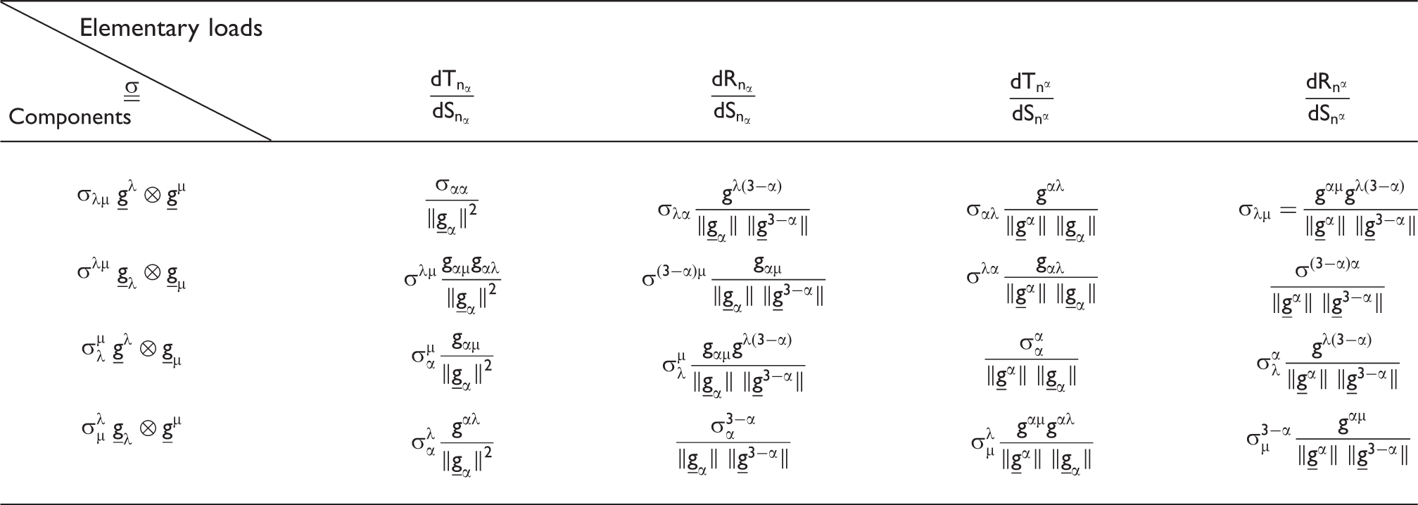
The inverse relationships, that is the elementary load components as functions of the stress components are given in Appendix 1. When substituting equation (8) in equation (9), another form of equation (11) is obtained for Remark
Direct relationships
Among the Cauchy stress tensor components given in Table 1, some give direct relationships between the longitudinal elementary loads and the direct stress components. That means that these loads only depend on these components and reciprocally. Others give direct relationships between shear stress components and transverse elementary load components. Nevertheless, no component set gives a direct relationship between both direct and shear stress components and longitudinal and transverse elementary load components.
The following section illustrates the above.
Direct stress components only depending on longitudinal loads
Among the Cauchy stress tensor components given in Table 1, two give a direct relationship between the longitudinal elementary load and the direct stress component. Considering the normal 
The direct stress component in a given direction is directly linked to the longitudinal force in the same direction. The corresponding shear stress component is the following:

It is linked to both longitudinal and transverse force components. Consequently, with such a choice of material normal direction and variance, direct stress components are directly linked to longitudinal force components but shear stresses are linked to both longitudinal and transverse forces. Furthermore, considering the normal 
Here again, the direct stress component only depends on the force component in the same direction, but the expression of the shear stress component is more complicated (see Table 1).
With another variance, direct stress components are related to both longitudinal and transverse loads (and the other longitudinal loads are related to both normal and shear stresses).
Equations (12) and (14) are direct relationships between direct stress components and longitudinal forces. But in both cases, the corresponding shear stress components do not only depend on transverse forces.
If the elementary longitudinal load is equal to zero, the direct stress components are also null and a direct relationship is obtained between the transverse loads and shear stresses:

Shear stress components only depending on transverse loads
A similar discussion can be held looking for a direct relationship between shear stresses and transverse forces. Among the Cauchy stress tensor components given in Table 1, two give a direct relationship between the transverse elementary load and the shear stress component.
Considering the normal 
In addition, considering the normal 
The other shear stress components are related to both transverse and longitudinal loads (and the other transverse loads are related to both shear and direct stresses).
If the shear stress component considered in equations (16) and (17) are only depending on the transverse elementary load, the corresponding direct stress components are depending on both longitudinal and transverse elementary loads. If the elementary transverse force is equal to zero, shear stress components will be null and a direct relationship is obtained between longitudinal loads and direct stress components:

Direct dependency of stress components on loads
It is interesting to have direct stress components that only depend on elementary longitudinal loads dT, and shear stress components only depending on transverse loads dR.
Two different cases can be distinguished
In the case of combined loadings: only two choices of variances enable to obtain a direct relationship either between the longitudinal load components and direct stresses (equations (12) and (14)) or between the transverse load components and transverse stresses (equations (17) and (18)). Unfortunately, these variances do not correspond to the same frame and consequently, there is no tensorial basis in which the normal stress components only depend on longitudinal loads and shear stress only depends on transverse loads. In the case of a longitudinal loading (
Other stress tensors
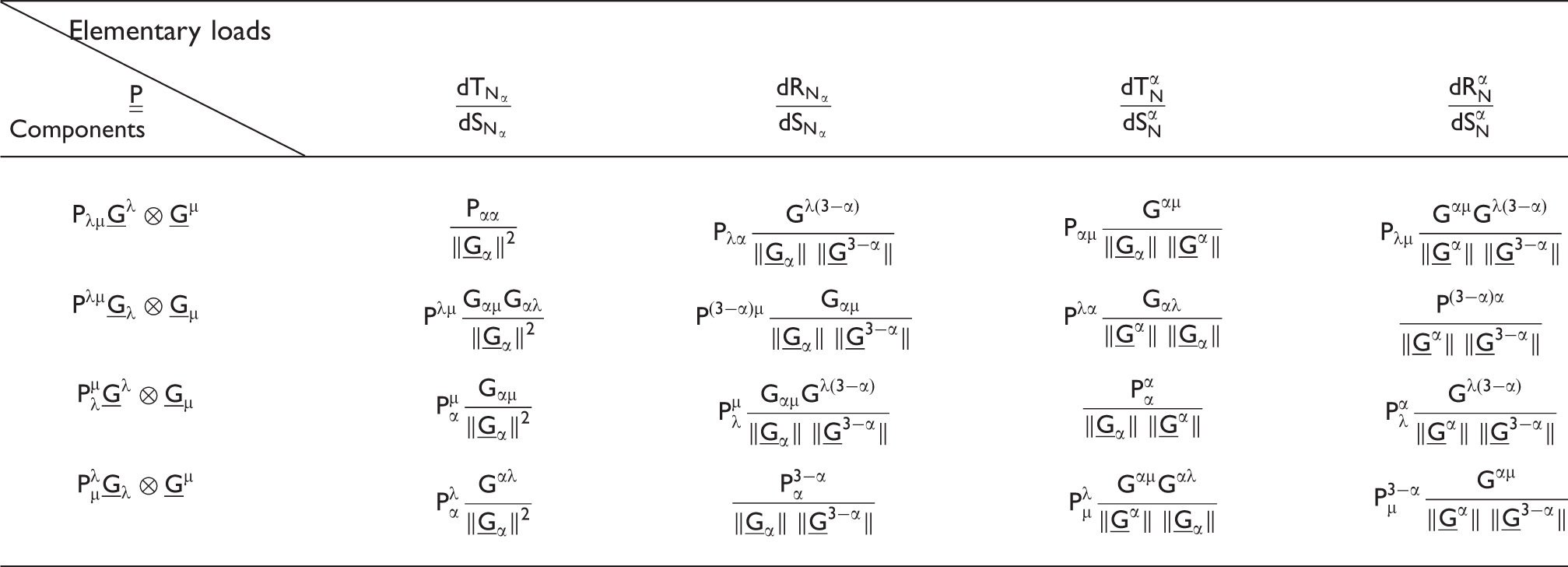
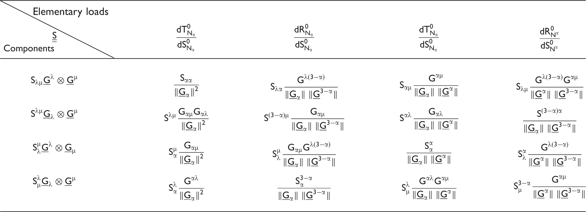
The developments are presented here for the Cauchy stress tensor, but similar calculations can be performed for the first and second Piola-Kirchhoff stress tensors. The same type of expressions and conclusions are obtained and briefly presented in Appendix 2.
Textile composite reinforcement
Introduction
The specific mechanical behaviour of fibrous materials is mainly due to their micro-structure. They are made of fibres that can be loaded in tension in their direction. Transverse loads, contact and friction between the fibres are also possible, but contrarily to standard continuum materials, relative sliding of the fibres is possible. This leads to a strong anisotropy and to weak values for some stiffnesses, especially for in-plane shear and bending rigidities.30,31 The tensile stiffness is preponderant over the others. The frames defined by the fibre directions are preferred to express the stress tensor components and the mechanical behaviour of textile materials. These directions are also important to define the pure tensile state for which there are only tensions in the fibres and the pure shear state for which there is no tension in the fibres.
A consistent identification of the homogenized behaviour law requires the knowledge of the relationship between loads and stresses. It is important to precisely define which stress components are related to the prescribed exterior load. This is done below in the case of the picture frame test, biaxial tensile test and combined test.
The textile material considered here has two yarn directions. For instance, it can be a woven fabric or a biaxial Non Crimp Fabric (NCF). The bending stiffness of the material is small enough to make a membrane assumption.
Referring to the notations used in the section Relationship between loads and stress components for a 2D continuous material and Figure 2, the two fibre directions are orientated along Basis, normals and elementary loads in the case of a 2D textile reinforcement.
Tensile and in-plane shear loading on a fabric
Let us consider a textile material with two fibre directions that is only submitted to tensions in the fibres. The elementary section (a) Pure tensile loading, (b) Pure in-plane shear loading.

The loads
(Remark:
In the case of a pure in-plane shear loading, the tensions in the fibres are equal to zero (Figure 3(b)):

In any case, because section
This is specific to the textile materials for which the tensions in the warp and weft fibres are well defined as the interior load in the fibre direction. In a pure tensile state, there are only loads in the fibre directions (equation (19)). In a pure shear state, the tensions are equal to zero (equation (20)).
Cauchy stress components
The relationship between elementary load components and covariant, contravariant and mixed components of the Cauchy stress tensor can be established from the section Relationship between loads and stress components for a 2D continuous material and can be particularized for pure uni- or biaxial tensile and in-plane shear loadings.
The aim of the present section is to specify in which basis the stress components should be written to perform the identification of the fabric behaviour from standard mechanical tests. Tensile and in-plane shear loadings are considered below.
Pure tensile loading
A pure tensile load is such as 
In the case of a pure tensile test, only the use of the contravariant components of the Cauchy stress tensor enables to have the shear stresses null and the normal stresses directly related to the longitudinal loads.
Pure in-plane shear
A pure in-plane shear loading is such as 
In the case of a pure in-plane shear test, only the use of the first mixed components of the Cauchy stress tensor enables to have the direct stresses null and the shear stresses directly related to the transverse loads.
Determination of the stress tensor components from standard experimental tests
Pure shear test: picture frame
Presentation and assumptions
In-plane shear is the main deformation mode for textile materials because it is necessary to drape the fabric on a double curved surface. The in-plane shear mechanical behaviour has been intensively studied, mainly using picture frame tests and bias extension tests.32–44 A picture frame test is considered in Figure 4. A hinged frame with four bars of equal length is assembled in a tensile testing machine. A tensile force is applied across diagonally opposing corners of the picture frame rig, causing the picture frame to move from an initially square configuration into a rhomboid. This principle enables to obtain a uniform pure shear loading if experiments are carefully performed in the frames defined in Figure 4.
Instrumented picture frame test. (a) Shear anglre = 0° (b) Shear anglre = 30°.
The following relationships can then be written:

Identification of the stress state
Frame and specimen parameters.
Referring to the Textile composite reinforcement section, the only stress variance that leads to a zero direct stress component is the mixed one 
The fixed frame
Let us consider the curvilinear coordinates 

The corresponding contravariant vectors are such as:

The summation of 

A normalized non orthogonal frame is defined in order to ease the physical interpretation of the stresses:

It leads to:

The static equilibrium of the frame enables to write the loads exerted on the frame arms as a function of the shear moment. Introducing the force exerted by the tensile device, one can obtain:

If the sample is square, w1 = w2, the mixed components for the Cauchy stress tensor are identical:

The previous result gives the mixed component of the shear stress (σ21)N as a function of the shear angle.
An example is presented in Figure 6. The fabric is a Twintex® plain weave
42
composed of glass fibres (60%) and polypropylene fibres (40%) (743 g/m2). The sample is a cross shape specimen 200×200 mm2, with 1.2 mm thickness (Figure 6(b)).
Tangential stress measured in a picture frame test. (a) Twintex® plain weave (b) Cross specimen (c) Shear Load F in function of the shear angle (d) Normalized tangential stress (σ21)N.
Biaxial tensile test
Presentation and assumptions
The tensile behaviour of woven fabrics is non-linear and biaxial because of the weaving and of the related crimp.45–48 Different load-strain curves are obtained when the warp-weft deformation ratio Kt is fixed. They are experimentally obtained using specific devices for biaxial tensile tests such as shown in Figure 7.
Biaxial tensile device and cross shape specimen.
The test consists in imposing different strain ratios in the two yarn directions of the fabric cross sample. The yarn directions remain constant and there is no in-plane shear strain. The strains are generally measured by a DIC system.43,47 Figure 8 shows the biaxial tensile curves for the Twintex plain weave. Stresses and strains are assumed to be uniform on the sample. The fabric thickness (e) is assumed to be constant because of the small value of the longitudinal strains.
Warp and weft tensions in function of the biaxial strain ratio 
Identification of the stress state
The angle between warp and weft directions is Initial and current state of a fabric under biaxial loading.
The length 

One can write for any point M of the fabric:

Let us denote T1 and T2 the macroscopic tensile loads measured on the biaxial tension device (Figure 9). One can define the global tensile load as the sum of the local tensile loads:

The stress tensor components that will be considered are those that lead to simple relationships with the internal loads. Equation (21) gives a direct relationship between the tensions and the contravariant components of the Cauchy stress tensor. Assuming that 
That leads to:

The Cauchy stress components matrix in the covariant basis is diagonal as expected. Direct components are simply deduced from the measured tensions in the yarn directions. Those contravariant components are given in a non-unit frame 
When γ=0, the obtained result logically corresponds to the standard form for two orthogonal networks. An example is given on Figure 10 for an orthogonal equibiaxial loading on the Twintex® plain weave. (The axial strain in warp and weft directions are equal.) The sample considered is a 50×50 mm
2
cross sample, with a 1.2 mm thickness.
Warp tension and associated contravariant normal stresses 
Combined shear and tensile loading
In the present section, in-plane shear and tension are simultaneously applied to the sample. The components that are considered are those identified in the Relationship between loads and stress components for a 2D continuous material section to give direct relationships between tension and direct components on one hand and between transverse forces and shear components on the other hand. This type of loading can be generated using the instrumented picture frame, presented in the Pure shear test: picture frame section and Figure 4 or an instrumented bias test. 49 The sample is supposed to be square.
Identification of the stress state
From the Textile composite reinforcement section, direct relationships between stresses and loads can be written for tensile and shear loading, respectively:


If the Cauchy stress components have to be expressed using the same variance, either the contravariant or the mixed components can be used
Contravariant components
If the choice is made to work with the contravariant components, one can obtain for the transverse components:

As shown in Appendix 1, the direct stress components are less simple and depend on Rα:

Using equation (35), for a square sample, the contravariant Cauchy stress components become:

Introducing the normalized stresses in the same way as for equation (30):

With such variance, if the shear stress component is simple and directly related to the transverse forces, the direct longitudinal components of the Cauchy stress tensor can be calculated but are more complicated and depend on both tension Tα and shear load F.
Mixed components
The same work can be done for the mixed components:


As expected, with such variance, the conclusions are different.
Introducing the normalized stresses (equation (30)):


Stress state in the case of a combined loading
Figure 11 presents experimental results for a coupled shear and tension test on the Twintex® plain weave. These results have been obtained performing a picture frame test on an initially tensed sample.
50
The tensile system enables to measure and control the tension evolution during the test so that any kind of combined loading can be imposed
39
(Figure 4). The real shear angle is measured directly on the sample using optical measurements through a marker tracking software. In the case presented here, the protocol consists in applying a pretension on the sample before it is sheared, its lengths remaining constant. The resulting tensions in the warp and weft directions and the frame load F are measured by the load sensors. Due to the limit conditions imposed by the picture frame, tensions in the yarns change with the shear angle.
50
Figure 11 depicts the two tensions and the frame response as a function of the shear angle. The previous results enable to plot the stress components directly related to the measured loads, which are the mixed normal stresses and the contravariant transverse stresses (Figure 12). On the other hand, it is also possible to express all the stress components of the same variance so that the complete stress tensor is given (Figure 13) in any variance. But there is no simple physical interpretation of the latter values.
Results of a coupled shear/tension test using an instrumented picture frame. (a) frame load (b) warp tension (c) weft tension. Stresses components directly related to the measured loads. (a) Contravariant Tangential stress (b) Mixed direct stresses. Other components of the stress tensor for the variances used Figure 12. (a) Mixed tangential stress (b) Contravariant direct stresses.


A consistent stress state has been obtained for a combined loading. Direct components only depending on the tensile state, and tangential components only depending on the shear state have been calculated, so that the stress state in the case of a combined loading is physically related to the loading.
Conclusion
The global loads measured during a picture frame test, a biaxial tensile test and a combined shear/tension test have been related to the stress components in the specimen. In the case of a picture frame test, the matrix of the mixed stress components in null on the diagonal. The shear stress components have also been given in function of the load on the picture frame. In the case of a biaxial tensile test in two non-orthogonal directions, the matrix of the contravariant stress components is diagonal and the two direct stresses have been related to the two tensile loads on the device. These results have been extended to the case of a combined shear/tensile test.
As the loads on the picture frame or tensile machine are crucial quantities measured during the test, their relation with the stress components are of major interest. It is the objective of the present paper to determine what the stress components are for which the shape of the component matrix is specific with only direct stress in tension test and shear stress in shear test. The relationships with the exterior loads have been given.
This work covers stresses and loads. Our next step will be to expand to strain fields in the specimen and to constitutive behaviour tensors.
Footnotes
Funding
This research was supported in part by the French Agency for Research (ANR) in the scope of the project LCM3M.
Conflict of Interest
None declared.
Appendix 1
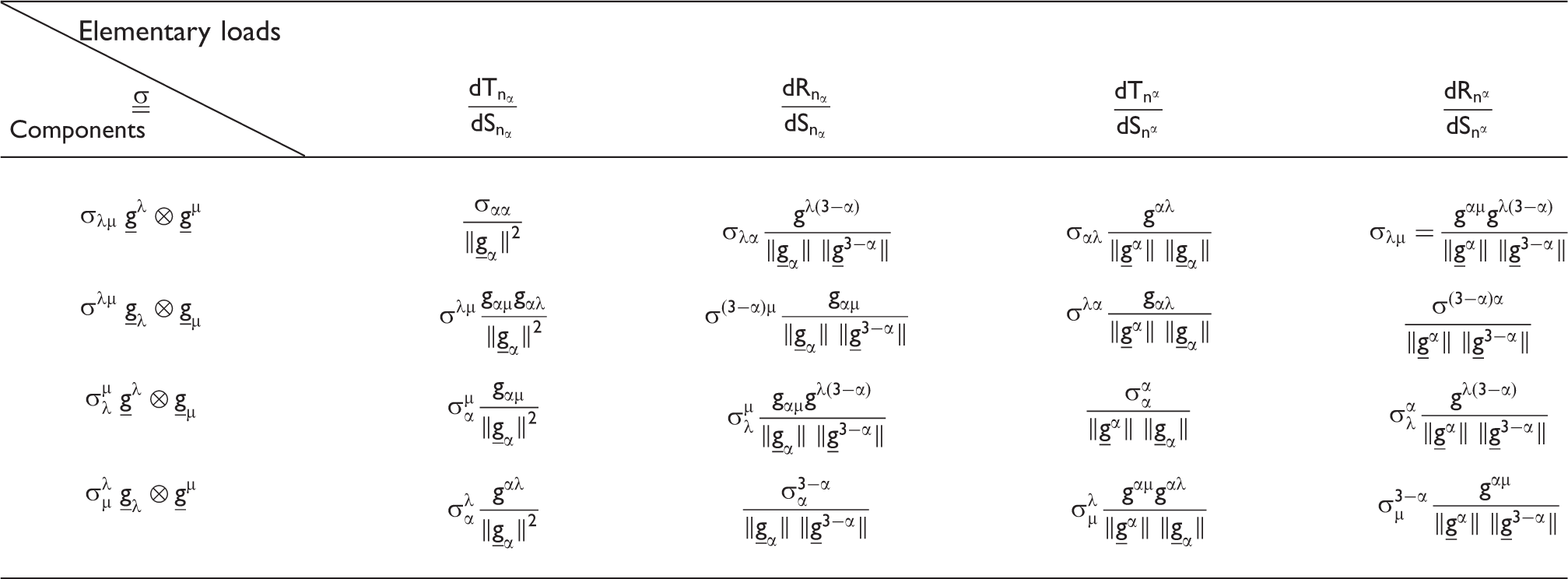
Elementary load components according to the normal choice as functions of the Cauchy stress tensor components in the different basis (covariant, contravariant and mixed)
Elementary loads as functions of the Cauchy stress tensor components
Elementary loads


Appendix 2
If the covariant and contravariant vectors in the initial configuration are denoted
The elementary loads in the initial configuration on the surface elements
The elementary loads in the actual configuration brought back to the initial surface elements
The relationships between the first and second Piola-Kirchhoff tensor components and the elementary loads can then be calculated and are presented on Tables B1 and B2.
Elementary loads as functions of the first Piola-Kirchhoff stress tensor components Elementary loads as functions of the second Piola-Kirchhoff stress tensor components
Elementary loads


Elementary loads


Appendix 3
From equation (11), we have
Then,
From the combination of equations (8) and (9) we have
Demonstrating the compatibility of equations (C3) and (C4) then consists in establishing
Since gi are the covariant vectors and gi the contravariant vectors, we have the following properties:
From these properties, we have
We obtain