
Abstract
A new mathematical model and its analytical solution for the analysis of the stress–strain state of a linear elastic beam cracked in flexure and strengthened with plates on its lateral sides is presented. Both the longitudinal and the transversal interactions at the side plate/beam interface are considered. Linear behaviour of the contact connection is assumed. The method is based upon the linearised planar beam theory of Reissner. The weakening of the beam induced by the flexural crack is modelled conventionally as a rotational spring. The suitability of the theory is demonstrated in a case presentation involving the comparison between analytical results of the present beam (one-dimensional) model, the experiments and the numerical results of a full three-dimensional solid model created in the LUSAS finite element analysis software. An excellent agreement between the results is observed and the proposed formulation is found to be accurate and reliable. Finally, the solution is employed in an engineering analysis, discussing the effects of the material and the geometric properties of selected characteristic cases of the observed beams on the static and kinematic quantities, including the boundary conditions of the side plates, the longitudinal and the transversal stiffness of the connection, the size of the cracks, the span of the beam, and the length and the stiffness of the side plates. For the cracked cantilever beam, a substantial effect of any of these parameters is found. In contrast, for the cracked two-span continuous beam, only the effect of the stiffness of the side plates and the effect of the length of the beam spans are noticeable.
Keywords
Introduction
Composite structures composed of two or more layers of different materials bolted or adhesively bonded one to another are one of the peak engineering solutions of the past few decades. The vast majority of them cover reinforced concrete and steel–concrete composite beams. Due to their highly efficient structural form composite structures are used widely in design of new building infrastructure and also in renovation and retrofitting design, where most frequently strengthening of a flexural beam is required. When discussing strengthening of a reinforced concrete (RC) flexural beam, the tension-face plating method is engaged as a rule.1,2 Due to a common misbelief of practice engineers that alternative solutions with side plates are in general less efficient, the side plating retrofitting technique is used in most cases only as a second choice (e.g. when the tension-face plates due to structural or aesthetic barriers are not possible). The misconception of the poor performance of the side strengthening plates has been overruled already in the late nineties and also later, when several authors1,3 discovered that the side plates not only can very efficiently enhance the bearing capacity of a beam but can, in some cases, exhibit a lower rate of loss in ductility. Nevertheless, the side plates solutions still seem to remain kept in the background.
The theory of mechanical behaviour of externally strengthened (plated) flexural beams originates from the theory of multi-layer beams, whose development has first started in the middle of the last century and is still being upgraded nowadays. An extensive overview of the work in this field was presented, e.g. by Čas et al., 4 Kroflič et al.,5,6 Milner and Tan, 7 Pizhong and Fangliang, 8 Ranzi et al., 9 Schnabl et al.10,11 However, in spite of all similarities to standard multi-layer flexural beams, the plated flexural beams are subjected to a specific form of failure, 2 and hence should be analysed in a specific way. For the RC flexural beams strengthened with a tension-face plate, for example, failure may not only occur due to an exceeded longitudinal bearing strength of the interface connection, familiar in the standard composite beam theory, but also by de-bonding the beam from the plate in the transverse direction initiated by the opening of a flexural crack. Furthermore, a pronounced transversal partial interaction between the layers (otherwise of a negligible nature in the vast majority of cases of standard composite beams) is also observed for flexural beams with plates bonded to their sides. Much attention to these fundamental questions has been paid by researchers since the late nineties, when a systematic research on the mechanical behaviour of different types of plated structures (tensile-face plated structures, side-plated structures, structures with externally bonded wraps, etc.) was launched. 12 Since than different aspects, e.g. the suitability of different plate types regarding different types of the beam damage, the ductility performance of different plate types, the effect of the type of plates upon failure modes of a damaged beam, local buckling of point-restrained side plates etc., have been investigated experimentally13–19 as well as computationally.20–27 The computational models have been either numerical20,21,23–25 or analytical, although only a few simplified analytical models can be found.1,22,25 For the side-plated RC beams, an analytical model based on an assumption that the degree of the transverse partial interaction between the plate and the beam is a function of the difference between their curvatures, was presented by Nguyen et al. 1
The article presents a new analytical model for the stress–strain analysis of elastic beams damaged by flexural cracks and strengthened with two symmetrically attached longitudinal side plates. The mathematical model is developed for the beams with constant cross-sections and straight axes. The method is based upon the planar beam model of Reissner 28 assuming small deformations. In addition to the basic assumptions of the Reissner theory, the following assumptions are employed: (i) shear deformations are neglected, (ii) all layers, namely cracked beam and both side plates, are made of different homogeneous linear elastic materials, (iii) both the longitudinal as well as the transversal slips can take place at the side plate/beam contact, (iv) uplifting and penetrating of one layer into another, e.g. due to local buckling of a side plate, are neglected, and (v) the connection is supposed to behave linearly.
Cracks are a distinguishing phenomenon accompanying the progressing deterioration and eventual collapse of a structure. In general, one can obtain two different failure mechanisms. The first one occurs in structures subjected to a sudden impact loading, launching crushing of the material with a large-scale fracture processing zone. The second failure mechanism appears when a narrow band of localised deformation in a locally damaged material is formed. The process of deterioration is here accompanied with a narrow band of micro-cracks resulting in only one dominant macro-crack eventually causing a collapse of a structure or its part. Mathematical models used for the 3D analysis of a structural collapse are due to the obvious overall complexity of the described phenomena very complex and computationally very time consuming. Therefore, researchers still look for simplified mathematical models to explore the impact of cracks on the global behaviour of structures. 29 One such model that is often employed in exploring the impact of a flexural crack, replaces the crack by a rotational spring. 30 The properties of the spring are defined using the fracture mechanics principles. 31 This simple model is also employed in the analyses of the side-plated elastic beams damaged by flexural cracks presented in this article.
Apart from the introduction, the article comprises four sections. In the second section, the mathematical model of a side-plated elastic beam cracked in flexure is presented. The third section shows how the equations of the model are solved. A verification of the proposed formulation and an engineering analysis discussing the effects of material and geometric properties for two characteristic cases of side-plated elastic beams cracked in flexure on the static and kinematic quantities is presented in sections four and five. Conclusions are given in the last section.
Mathematical model
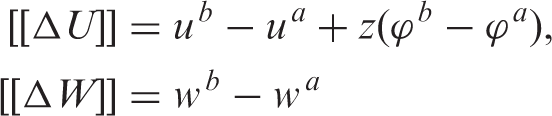
For the sake of simplicity of the derivation, a beam damaged by only one flexural crack is considered (Figure 1). We consider a straight elastic beam ‘a’ of initial length L
a
and cross-section Undeformed and deformed configurations of a side-plated beam cracked in flexure.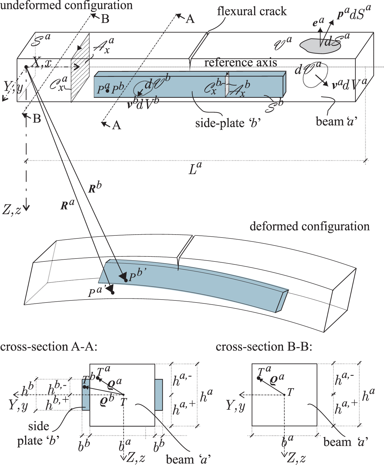
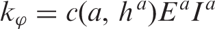
Rotational stiffness of the spring representing the effect of a flexural crack in a RC beam can be defined using the equation
31
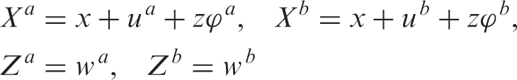
Furthermore, the loading conditions are assumed, that only deformations in the (X, Z)-plane of a global fixed spatial right-handed Cartesian coordinate system (X, Y, Z) with orthonormal base vectors Mathematical model of the side-plated beam cracked in flexure.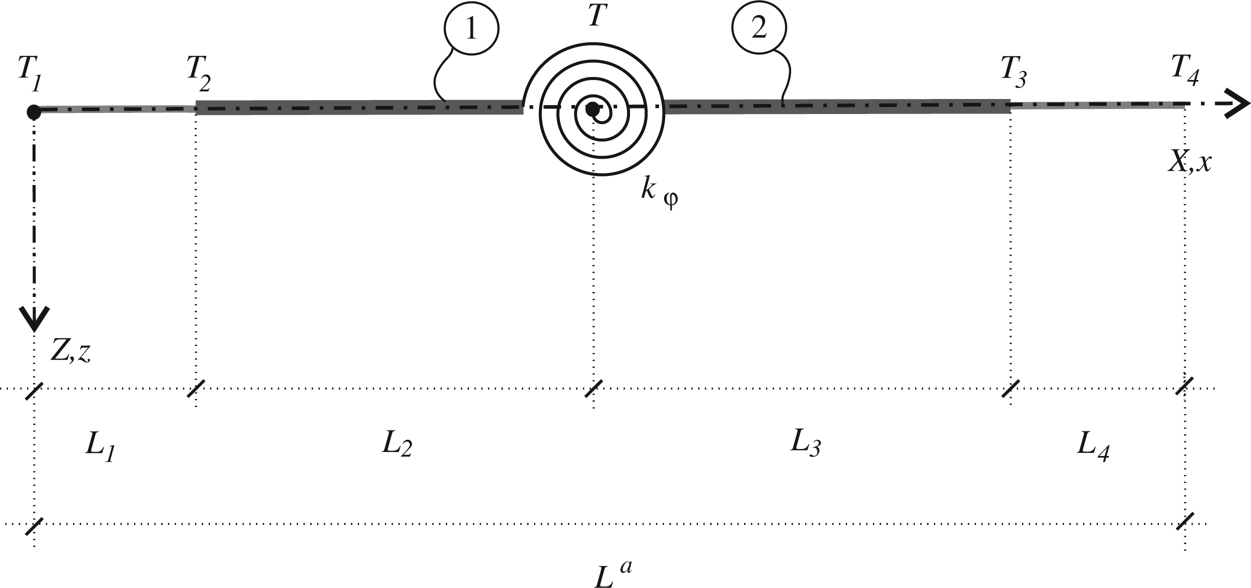
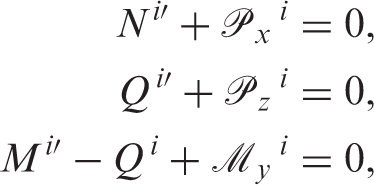
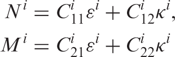
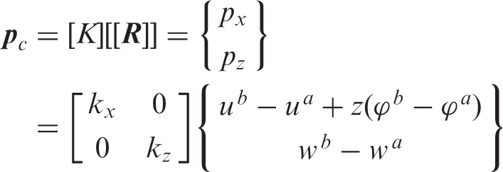
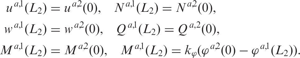
In what follows we present the governing equations of the plated part of the model. The static equilibrium of the side-plated cracked elastic beam is governed by the system of kinematic, equilibrium and constitutive equations, which we write separately for the cracked beam and the side plates. According to Hjelmstad
33
these equations can be summarised as follows (i = a, b)
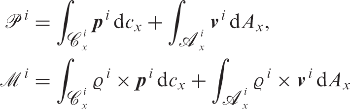
In the sequel a more detailed explanation of the part concerning the loading over the side plate/beam contact area is carried out. Following our initial assumption that each layer only deforms in the (X, Z)-plane, we conclude that the component of the contact traction in the direction of

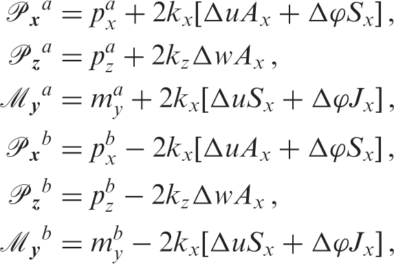
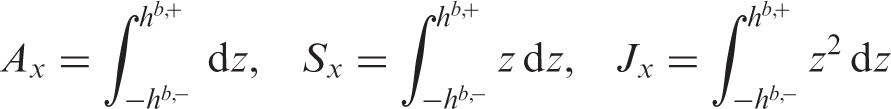
The system of equations of the side-plated beam, equations (2) to (4), consists of 4 algebraic and 12 ordinary first-order differential equations with constant coefficients. This system is applied for every plated segment of a beam. For the non-plated segments, the system reduces to the classical system of equations for a single beam. In analysing the side-plated beam, the nodal points are introduced first. They must include every change in geometry and loading. The region between the two nodal points is called a ‘segment’. Depending on the presence of the plate, each element is governed by an appropriate system of equations. The plated and the non-plated segments are, in nodal points, connected by a set of natural and essential boundary conditions, adequate to a specific case under consideration. The proper boundary conditions are necessary for obtaining the unique solution. The boundary conditions set at the crack location should incorporate the weakening effects of the crack. In this article the crack is assumed to have only an influence on the rotations of the beam and is, hence, modelled as a rotational spring. Let us consider the plated area of the beam shown in Figure 2 (part
Method of solution
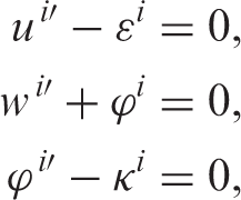
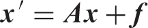
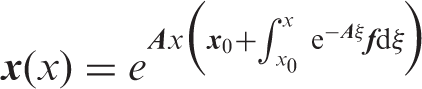
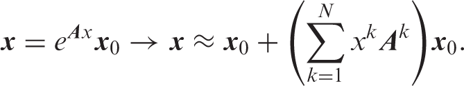
The system of equations of one side-plated segment consists of 4 linear algebraic and 12 linear ordinary differential equations. After substituting ɛ
i
and κ
i
from equation (4) into equation (2) and inserting
Verification of the model
The objective of the section is to verify and validate the proposed model. Because often mistakenly judged as less efficient, the side-plating technique has been less often investigated and thus the reports on experiments are rare and sometimes difficult to find. Two experimental investigations were found to be suitable for verifying the present model and the results of comparisons are presented in the following two sections. Since the two experiments treated solely undamaged, i.e. non-cracked sections, an additional numerical example was discussed in the section ‘A side-plated cracked elastic cantilever beam’, where the present results of a side-plated cracked cantilever beam are compared with those of a full 3D solid beam finite element model created with the LUSAS finite element analysis software. While in the present (1D) model the crack of a selected depth was modelled as a rotational spring with an appropriate magnitude of the rotational stiffness described in the ‘Mathematical model’ section, the crack in the LUSAS software solid finite element code was modelled by solid (3D) finite elements by releasing the connection between the nodes of the finite elements along the expected crack, introducing this way the macro-crack.
A timber beam reinforced at the sides with FRP laminates
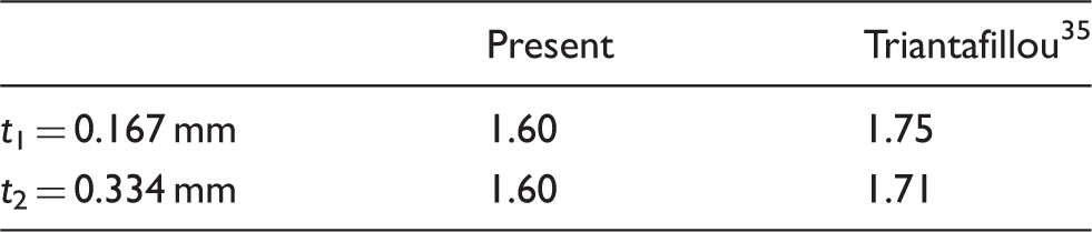
This section takes a brief look into the results of the lab-scale experiment of Triantafillou
35
exploring the improvements in the shear capacity of timber beams after reinforcing them with fiber-reinforced plastic (FRP) laminates. In the tests the beams were simply supported and subjected to two-point bending. Their typical cross-section was 65 mm wide and 100 mm high, except in the area of the shear span, where the width was in the experiment intentionally reduced to 25 mm to ensure that the shear failure would be the governing mode (Figure 3). The length of the beams was 500 mm. The bond between the beam and the FRP laminates was achieved using a structural epoxy adhesive. As reported by Triantafillou,
35
the FRP laminates had elastic modulus of 2.35 × 10⁴ kN/cm2, while the elastic modulus of wood was only estimated to be 1.2 × 10³ kN/cm2. The stiffness of the contact connection was k
x
= k
z
= 0.5 kN/cm3. Although the shear capacity of flexural beams is not a prime objective of this article, the part of the results of Triantafillou
35
can be used to verify the proposed analytical model. In Table 1, we present a comparison between the measured and the present results for mid-span deflections of the tested beam reinforced with FRP side-laminates. The presented deflections correspond to the load level P = 15 kN at which all the materials apparently remain (according to the load–deflections curves presented by Triantafillou
35
) in the elastic zone, so that the present analytical model is still applicable. The presented results for two different thicknesses, t1 and t2, of the FRP laminates obviously agree well.
Timber beam reinforced at the sides with FRP laminates tested by Triantafillou35: geometric properties and loading data (all units are millimetres). Timber beam reinforced at the sides with FRP laminates tested by Triantafillou35: A comparison between experimental and present analytical mid-span deflections in mm for two different thicknesses of the side–laminates: t1 = 0.167 mm and t2 = 0.334 mm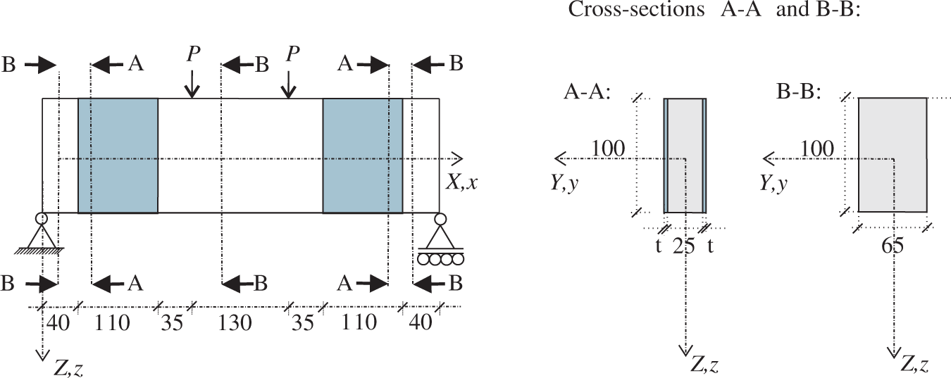
A simply supported RC beam with bolted steel side plates
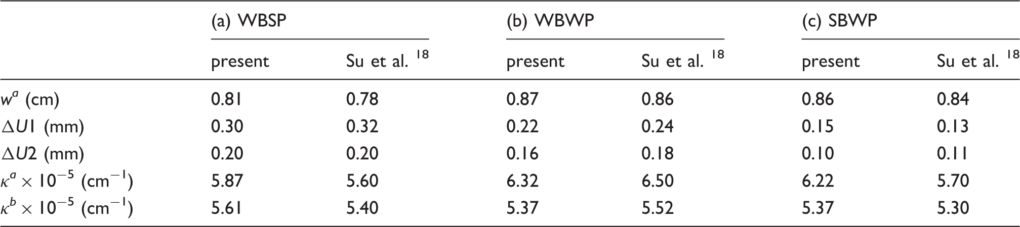
In this section the results of the proposed model are compared with the full-scale experiment of Su et al.
18
on a simply supported side-plated RC beam subject to a two-point bending. We present the results for the load level P = 50 kN and for three of the tested variations marked as WBSP (‘weak bolts–strong plate’), WBWP (‘weak bolts–weak plate’), and SBWP (‘strong bolts–weak plate’). Their geometric characteristics are schematically presented in Figure 4. As reported by Su
18
the steel plates had elastic modulus of 2.12 × 10⁴ kN/cm2 and the elastic modulus of concrete was 3.25 × 10³ kN/cm2. The stiffness of the contact connection was estimated from the bolt force–slip response and the details of the contact as given by Su et al.
18
For the beams WBSP, WBWP and SBWP, respectively, the contact stiffnesses were set to k
x
= k
z
= 0.07 kN/cm3, k
x
= k
z
= 2.07 kN/cm3 and k
x
= k
z
= 2.59 kN/cm3.
Simply supported RC beam with bolted steel side plates tested by Su et al.18: Geometric properties and loading data (units of the diameters of the bars and the bolts are millimetres, and centimetres elsewhere).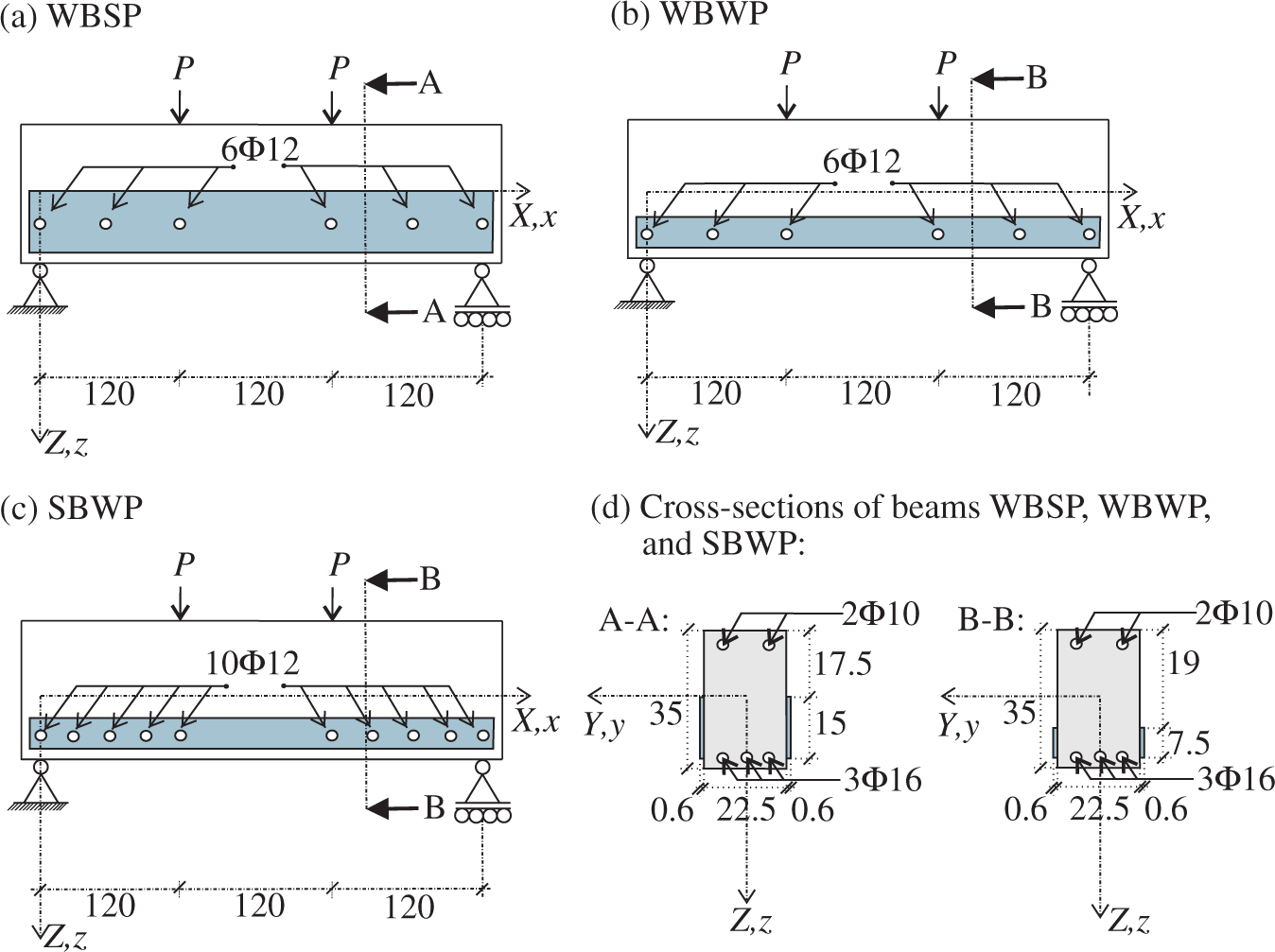
Because concrete is a material with undesirably low tensile strength that is usually (as in the present case) counteracted by the inclusion of steel bar, some modifications were needed in the evaluation of displacements, so that the proposed analytical model (valid only for homogeneous cross-sections) was applicable. The procedure for the displacement prediction of simple RC beams as suggested in the European Building Code EC2 36 was employed. Namely, in accordance with EC2, 36 the displacements of a RC beam can be calculated by combining the results of two sub-analyses, both accounting for a homogeneous material with the elastic modulus equal to the elastic modulus of concrete, yet at the same time employing two differently modified cross-sections. While a non-cracked cross-section with the full height (35 cm in the present example) is used in the first sub-analysis, the height of the beam is adequately reduced to 24.4 cm in the second one.
A simply supported side-plated RC beam. A comparison between experimental and present results for: mid-span deflections of the beam w a , longitudinal slips ΔU in the centre of the side plates (z = 7.5 cm) and at two distances from the left support of the beam (ΔU1 = ΔU(x = 20 cm, z = 7.5 cm), ΔU2 = ΔU(x = 100 cm, z = 7.5 cm)), mid-span curvature of the beam κ a × 10−5, and mid-span curvature of the side-plates κ b × 10−5
A side-plated cracked elastic cantilever beam
The third example aiming at a verification of the proposed model addresses an example of a side-plated elastic cantilever beam, 3.5 m long, damaged by a flexural crack, and strengthened with two side plates as presented in Figure 5. The crack is located 50 cm away from the clamped end of the beam and its depth is 15 cm. The beam is subjected to a point load 10 kN. The values of the elastic moduli of hypothetically ideally linear-elastic materials of the beam and the side plates, respectively, are chosen to be E
a
= 3.1 × 10³ kN/cm2 and E
b
= 2.1 × 10⁴ kN/cm2, whilst the contact stiffnesses k
x
= k
z
are 0.75 kN/cm3.
Geometric properties and loading data of the side-plated cracked elastic cantilever beam (units of all presented length quantities are centimetres).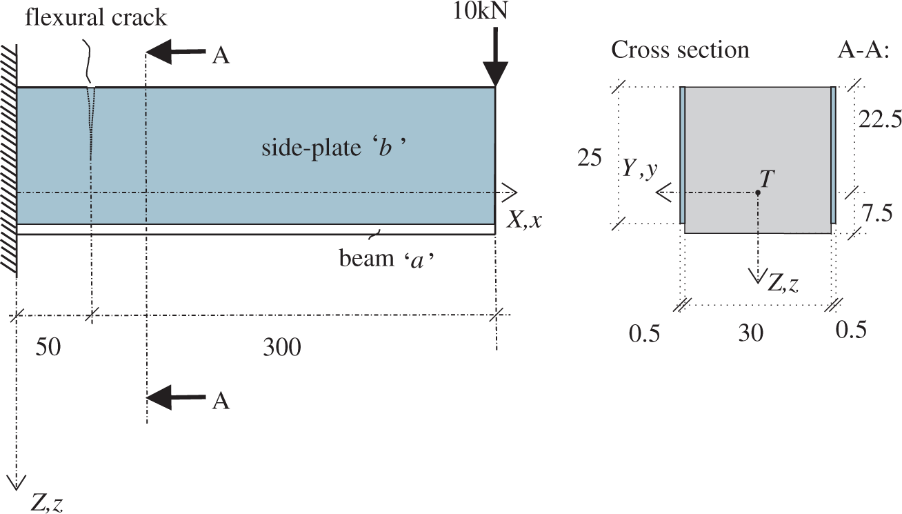
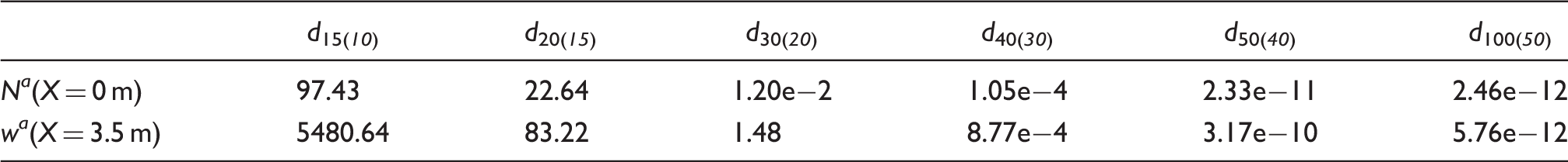
The relative error (in %) of the results for N a (X = 0 m) and w a (X = 3.5 m) for different number of terms in the series in equation (15)
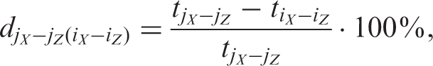
Relative errors (in %) of the results for N a (X = 0 m) and w a (X = 3.5 m) for different mesh densities of the 3D solid model
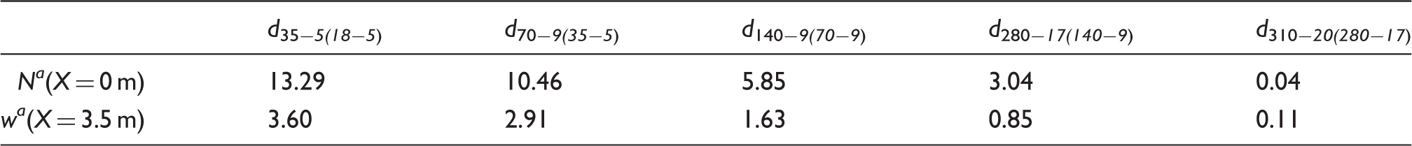
The requirement that the relative error be lower than 1% for both of the observed quantities shows that the numerical solution is sufficiently accurate for the ‘280–17’ mesh. This mesh consists of 280 × 17 × 4 beam FEs, 280 × 17 × 2 side-plate FEs, and 280 × 16 × 2 joint elements. This mesh density was used for all further 3D analyses in the example.
The selected number of terms of the series in equation (15) in the 1D beam model and the selected mesh density in the 3D solid LUSAS model were then used for the verification of the proposed beam model. The comparisons of the results of the two models for all essential quantities of the beam and its side plates along the beam length were carried out. The comparisons are presented in Figure 6. The figure shows an excellent agreement between the results and we can easily conclude that the present new mathematical model and its solution method represent a computationally efficient and sufficiently accurate tool for the linear analysis of side-plated cracked elastic beams with a partial connection.
Side-plated cracked elastic cantilever beam. A comparison between different static and kinematic quantities along the beam length obtained by the proposed planar beam model (‘-’) and the full 3D solid LUSAS model (‘□’): (a) shear forces, (b) bending moments, (c) axial forces, (d) vertical displacements, (e) longitudinal slips, and (f) transverse slips. The moments M
a
and M
b
are represented with respect to the reference axis of the beam. The values of the longitudinal slips, Δu, are valid at the top of the cross-section.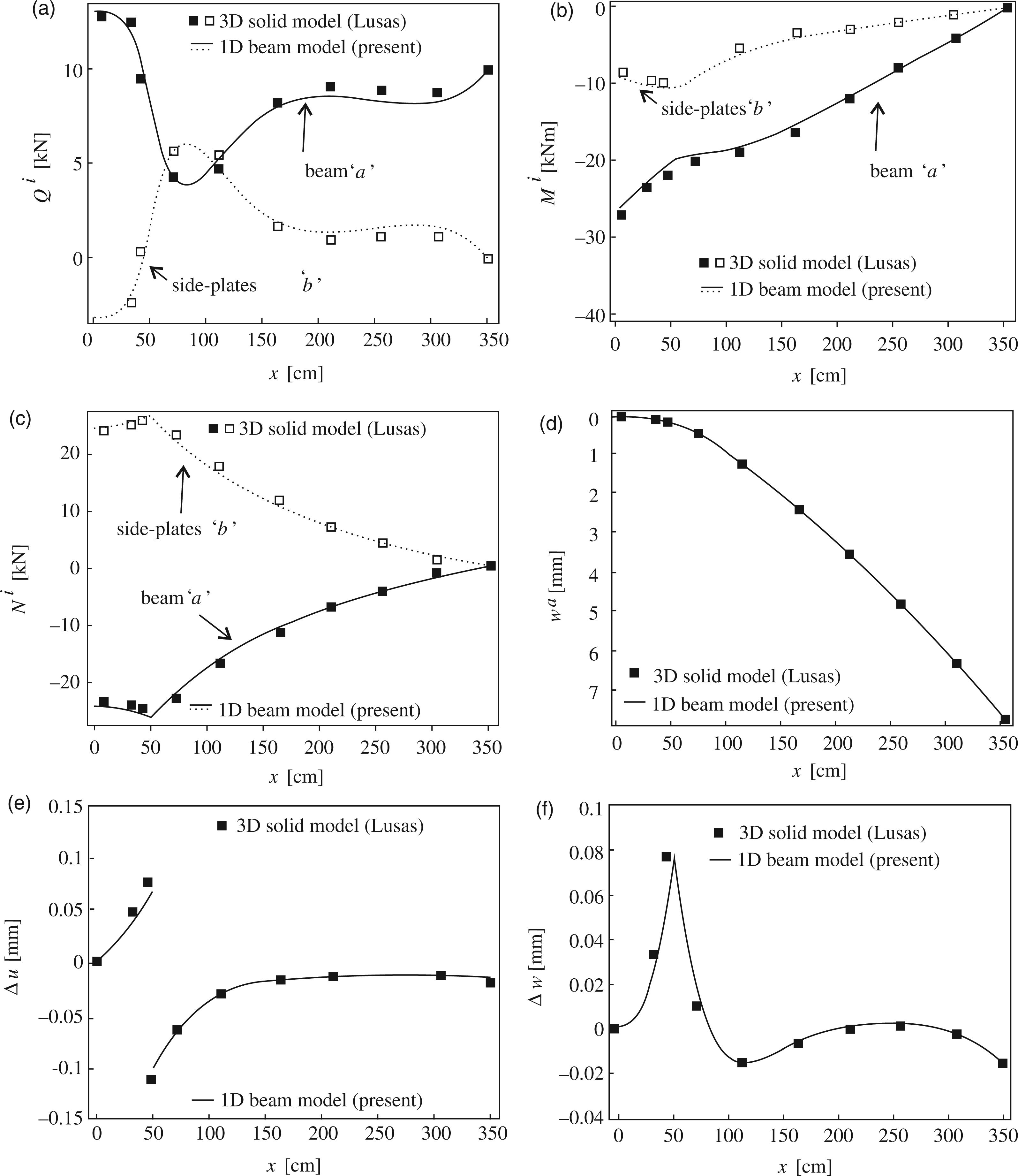
Parametric studies
In this section, the present formulation is applied in the mechanical analyses of two side-plated beams (in the sequel referred to as the ‘side-plated cracked elastic beams’). The objective of the two examples is the assessment of the effect of several material and geometric properties of cracked elastic beams when strengthened with side plates on the mechanical state in the beams. The latter is achieved by performing extensive parametric studies of the mechanical responses for two characteristic types of beams.
In all of the examples, the values taken as the input data are only hypothetical, chosen with a view to getting as eloquent and vivid graphics and conclusions as possible. Yet they represent potentially realistic situations.
Side-plated cracked cantilever beam
In our first example we analyse a side-plated elastic cantilever beam damaged by a single flexural crack. The crack is located 10 cm away from the fixed support of the beam. The beam is strengthened with two symmetrically attached side plates and is, at its free end, subject to a point load P = 10 kN (Figure 7). The values of the elastic moduli of the beam and the side plates, respectively, are E
a
= 3.1 × 10³ kN/cm2 and E
b
= 2.1 × 10⁴ kN/cm2, the latter value roughly corresponding to steel plates. Geometric properties of the beam are presented in Figure 7.
Geometric properties and loading data of the side-plated cracked elastic cantilever beam (units of all presented length quantities are centimetres).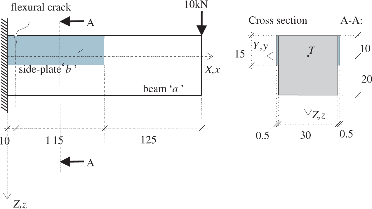
In this example we investigate the influences of the boundary conditions of the side plates, the stiffness of the interface connection between the beam and the side plates, and the depth of the crack on the static and kinematic quantities. The influence of the side plates boundary conditions on the variation of static and kinematic quantities over the beam axis is presented in Figure 8. Two realisations of strengthening are explored, the first one having the side plates, which are embedded in the fixed support of the beam, and the second one, where the ends of the side plates are not connected to the support. The contact stiffnesses k
x
= k
z
and the crack rotational stiffness kϕ, respectively, were taken as 0.25 kN/cm3 and 8.0 × 10⁵ kNcm. In accordance with our expectations, the results reveal the highest effect if the side plates are embedded in the support. In such a case, as shown in Figures 8(a) and 8(b), a large portion of the beam shear and bending is transferred from the beam to the side plates. By contrast, the alternative with free-end side plates tends to be inefficient and it can even increase the internal shear force in the beam (Figure 8(a)). The increase depends on the (E
a
/E
b
) ratio as well as on the contact stiffness of the connection. Furthermore, due to the composite action between the beam and the side plates, an increase in the beam and plate axial force is noticed for both the embedded and the free-side plate (Figure 8(c)). The axial force in the beam becomes compressive and rather high in the case of the embedded side plates. Figure 8(d) shows the effect of the side plates on the size of the transverse displacements of the beam. Again, a nearly negligible influence of the free and, in contrast, a substantial influence of the embedded side plate is observed. The transverse displacement of the unstrengthened beam at its free end is w
a
(x = L
a
) = 0.97 cm. This value decreases by approximately 22% after the embedded strengthening plates are applied. Furthermore, in Figure 8(e) and 8(f), variations of slip along the beam length are presented. Note that the longitudinal slips (Figure 8(e)) are much higher if the embedded plates are applied. The distribution of the transverse slips (Figure 8(f)) is very interesting, because the slip of the free-side plates is negative (which means that the transverse displacement of the side plates is smaller than the transverse displacement of the beam axis). In what follows, only the embedded side plates will be studied.
Side-plated cracked elastic cantilever beam. A comparison between variations of static and kinematic quantities along the axis of the beam for unstrengthened beam (‘o’), strengthened beam with side plates embedded in the left-hand fixed support of the beam (‘•’), and strengthened cracked beam with free-side plates (‘x’): (a) shear forces, (b) bending moments, (c) axial forces, (d) vertical displacements, (e) longitudinal slips, and (f) transverse slips. Side-plated cracked elastic cantilever beam. The side plates are embedded in the left-hand fixed support of the beam. A comparison between the variations of static and kinematic quantities along the axis of the beam for different crack properties: kϕ = 8.0 × 10⁷ kNcm (‘•’ – slightly cracked beam), kϕ = 8.0 × 10⁵ kNcm (‘x’ – highly cracked beam), and kϕ = 8.0 × 10⁴ kNcm (‘o’ – exceedingly cracked beam): (a) shear forces, (b) bending moments, (c) axial forces, (d) vertical displacements, (e) longitudinal slips, and (f) transverse slips.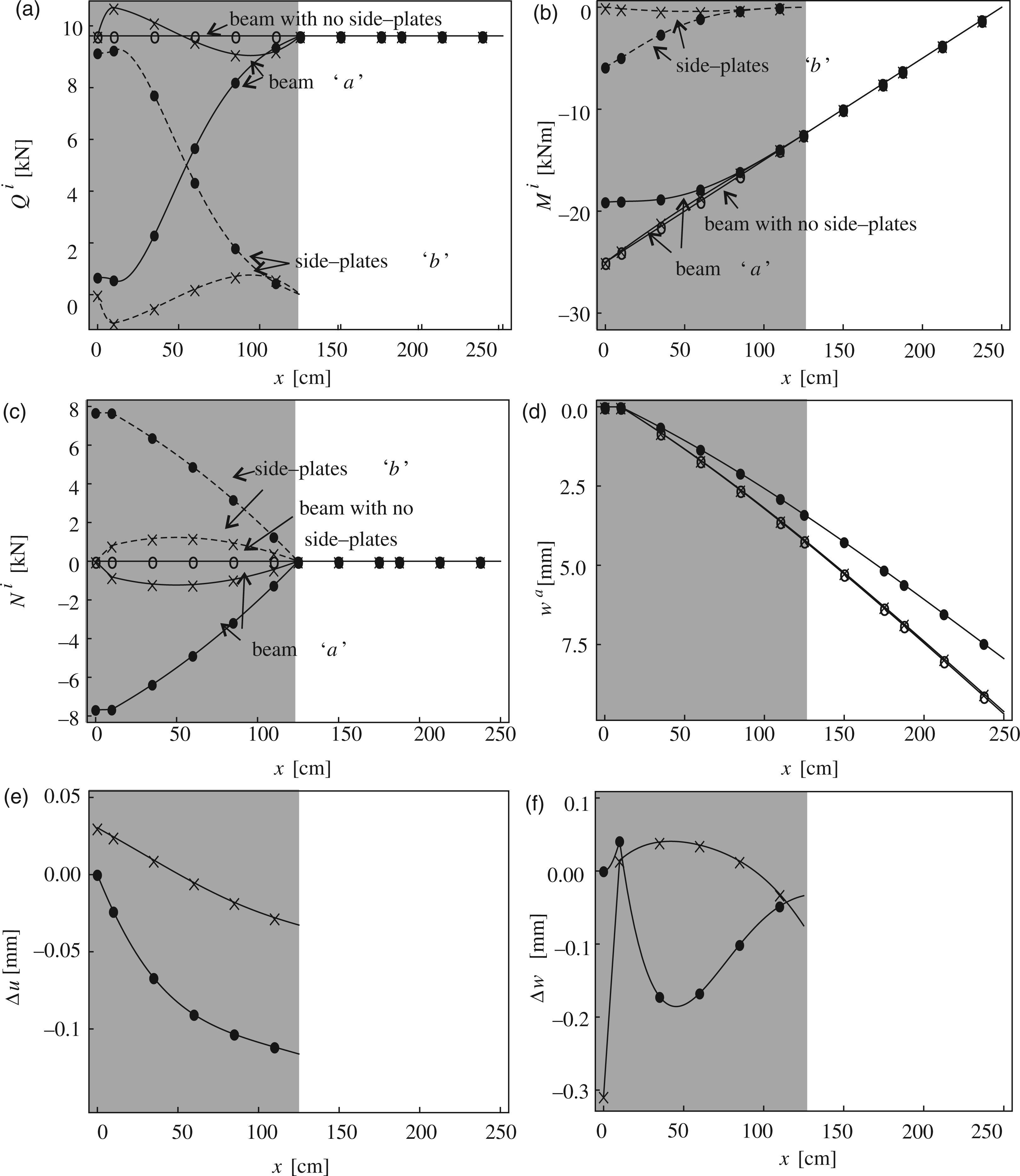
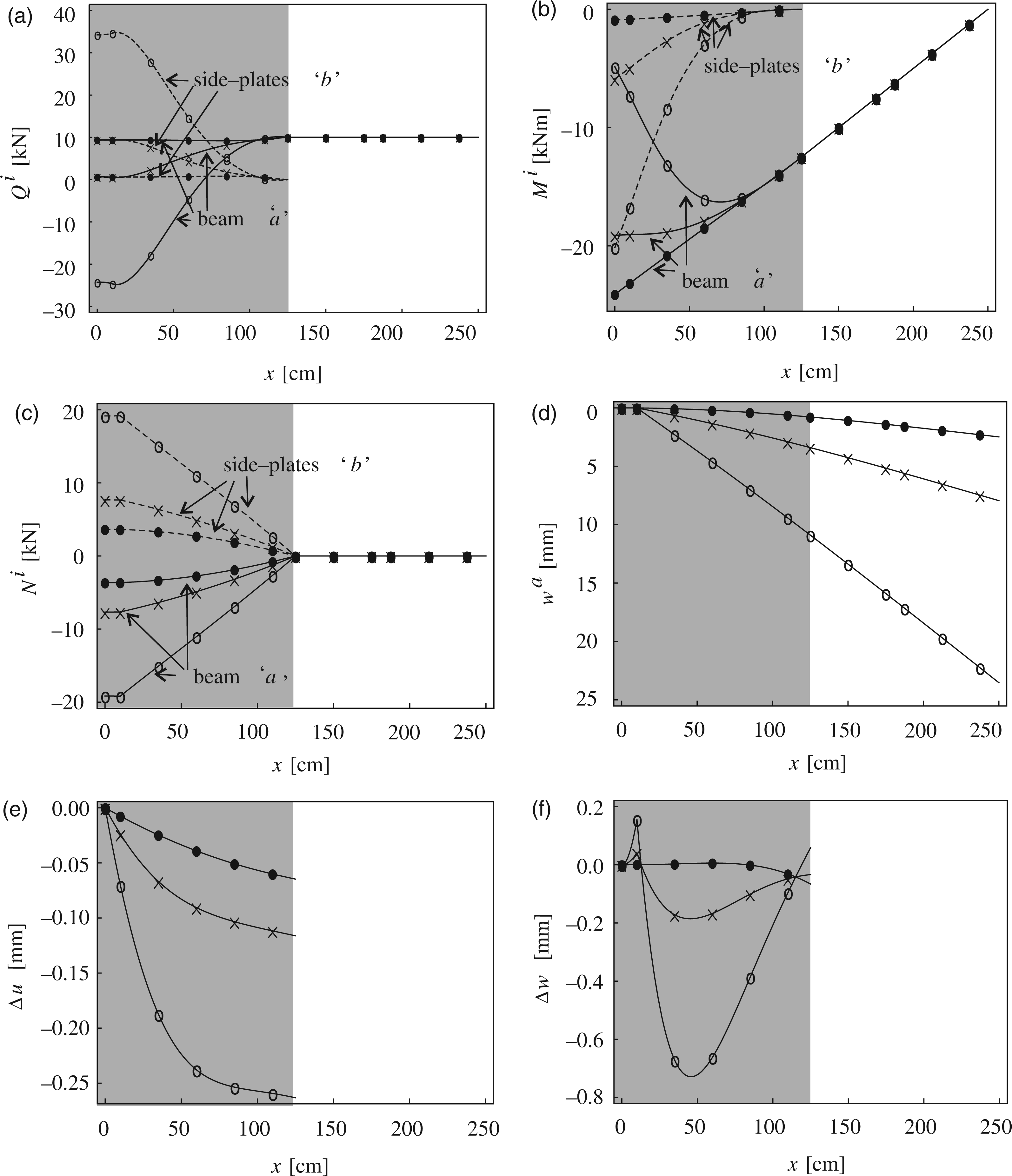
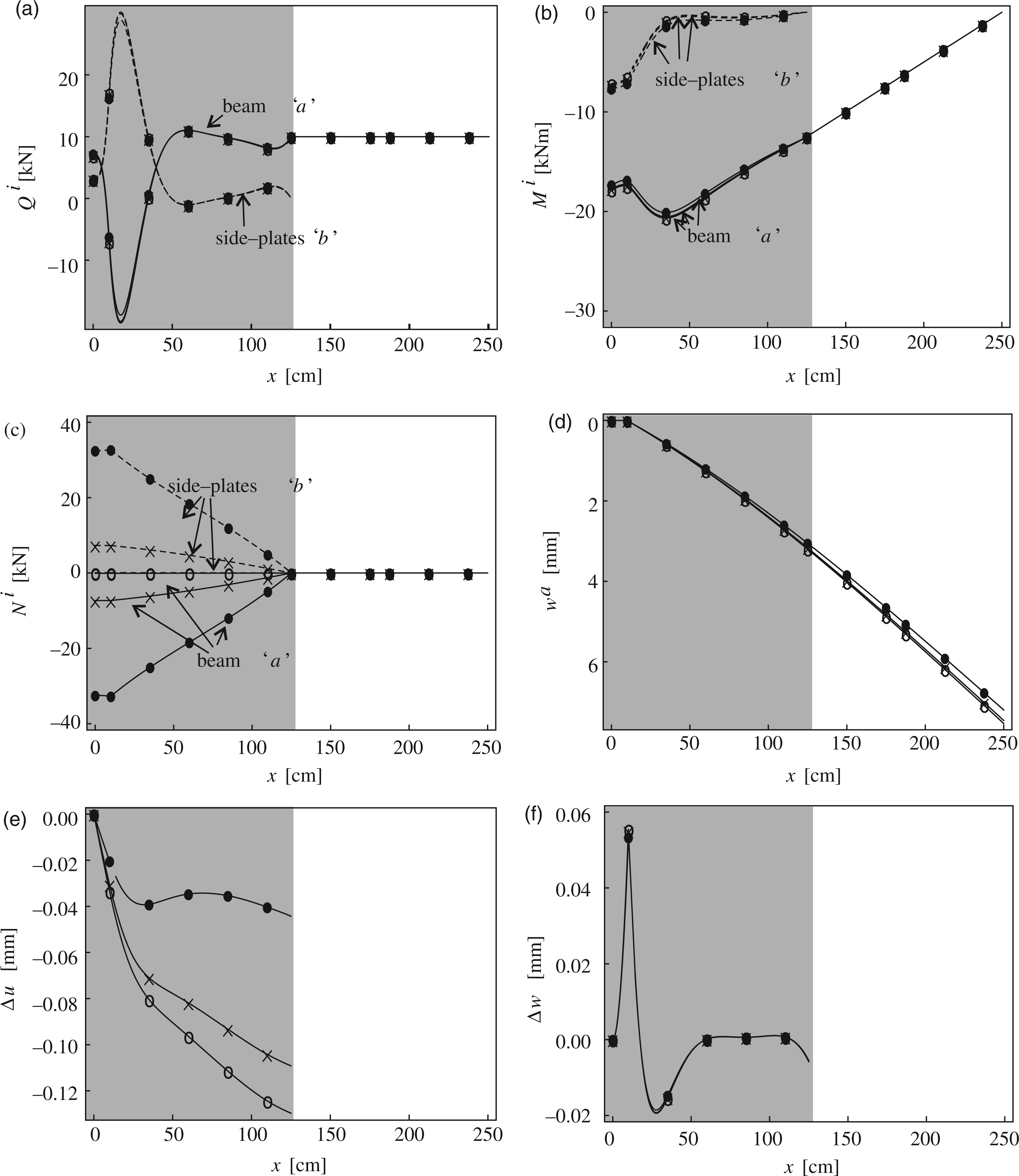
Figure 9 depicts the effect of the crack size on the mechanical response of the beam with the moderate connection (k x = k z = 0.25 kN/cm3). The following three values of the stiffness of the rotational spring are discussed: kϕ = 8.0 × 10⁷ kNcm (‘•’ - slightly cracked beam), kϕ = 8.0 × 10⁵ kNcm (‘x’ – highly cracked beam), and kϕ = 8.0 × 10⁴ kNcm (‘o’ – exceedingly cracked beam). The comparison of the results in Figure 9(d) reveals that the degree of the local damage highly determines the vertical displacements. Furthermore, high damage yields a pronounced load redistribution from the beam to its side plates. This is particularly true for the bending moment. Figures 9(e) and (f) indicate a progressive increase of slips with the increase of the crack depth.
The final analyses of the present numerical case of the side-plated cracked elastic cantilever beam will present the effects of different longitudinal and transverse contact stiffnesses. It is assumed that the contact stiffness in one direction is large, while the one in the other direction is varied. The effects of a very high longitudinal stiffness (k
x
= 25 kN/cm3) and a much smaller transversal stiffness (k
z
= 0.0025 kN/cm3 for a flexible transversal connection – ‘o’, k
z
= 0.25 kN/cm3 for a moderate transversal stiffness – ‘x’ and k
z
= 2.5 kN/cm3 for a rigid transversal connection – ‘•’) are displayed in Figure 10. In line with our expectations, the contact stiffness k
z
influences significantly the magnitude of the side-plated beam internal shear forces and the transversal slips. By contrast, the pronounced effect upon the longitudinal slips is rather unexpected. While, in this particular example of the side-plated beam, the effect of the increased transversal stiffness is in favour of the beam, i.e. the beam shear forces decrease after its strengthening, such an effect, however, is not necessarily self-evident in a general case; e.g. observe the increase of the shear force in Figure 8(a). This indicates that neglecting the effect of the transversal flexibility of the connection in the design process is, therefore, not always justified. In the second parametric analysis, whose results are gathered in Figure 11, the situation is different. Here the contact having different longitudinal stiffnesses and a very high transversal stiffness (k
z
= 25 kN/cm3) is considered. For the longitudinal stiffness k
x
, the following values have been assumed: k
x
= 0.0025 kN/cm3 (‘o’ – flexible longitudinal connection), k
x
= 0.25 kN/cm3 (‘x’ – moderate longitudinal connection), k
x
= 2.5 kN/cm3 (‘•’ – rigid longitudinal connection). The results show that the longitudinal contact stiffness has a negligible influence on the shear forces, the bending moments, and the vertical displacements of the beam and the side plates, while it highly effects the longitudinal slips between the beam and the side plates and, consequently, also the axial forces which significantly increase in the vicinity of the clamped end. The effect of the observed range of stiffnesses upon the transversal slips appears to be negligible in this case.
Side-plated cracked elastic cantilever beam. The side plates are embedded in the left-hand fixed support of the beam. A comparison between the variations of static and kinematic quantities along the axis of the beam with a rigid transversal connection (k
x
= 25 kN/cm3) and various k
z
values: k
z
= 0.0025 kN/cm3 (‘o’ – flexible transversal connection), k
z
= 0.25 kN/cm3 (‘x’ – moderate transversal connection), and k
z
= 2.5 kN/cm3 (‘• ’ – rigid transversal connection): (a) shear forces, (b) bending moments, (c) axial forces, (d) vertical displacements, (e) longitudinal slips, and (f) transverse slips. Side-plated cracked elastic cantilever beam. The side plates are embedded in the left-hand fixed support of the beam. A comparison between standard static and kinematic quantities along the axis of the beam with a rigid transversal connection (k
z
= 25 kN/cm3) and various k
x
values: k
x
= 0.0025 kN/cm3 (‘o’ – flexible longitudinal connection), k
x
= 0.25 kN/cm3 (‘x’ – moderate longitudinal connection), k
x
= 2.5 kN/cm3 (‘• ’ – rigid longitudinal connection): (a) shear forces, (b) bending moments, (c) axial forces, (d) vertical displacements, (e) longitudinal slips, and (f) transverse slips.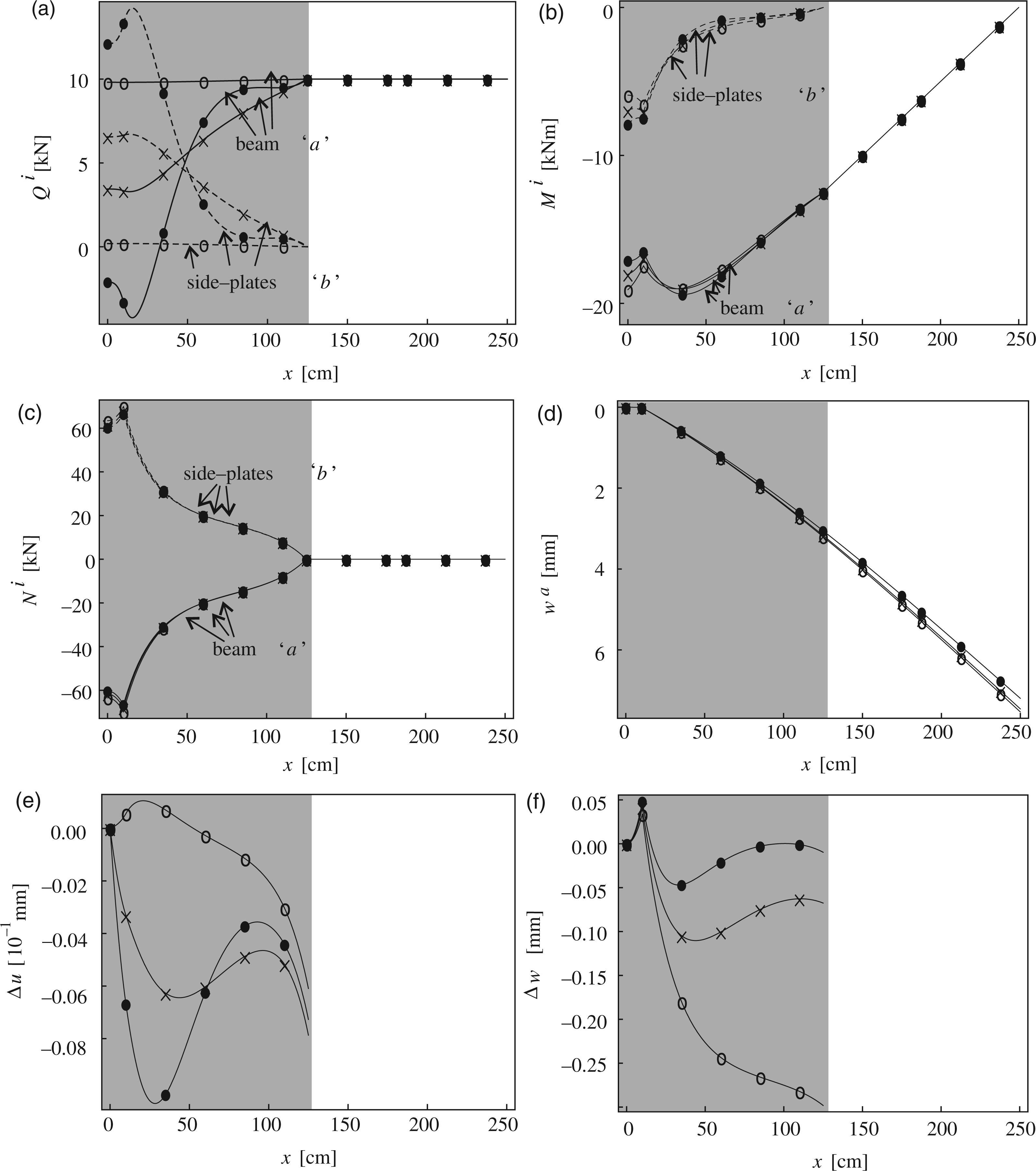
Side-plated cracked continuous beam
In our second example we analyse a side-plated continuous beam with a flexural crack at the midspan support (Figure 12). Elastic modulus of the beam material is E
a
= 3.1 × 10³ kN/cm2. The beam is subjected to the uniformly distributed load of intensity Geometric properties and loading data of the side-plated elastic continuous beam damaged by one flexural crack (units of all presented length quantities are centimetres).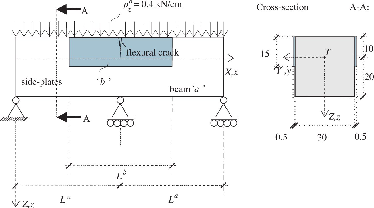
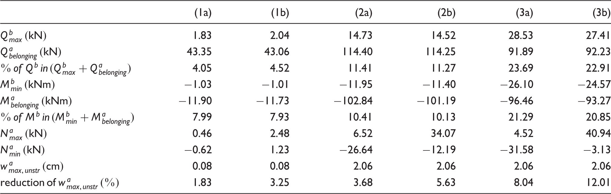
The comparison of static and kinematic quantities with different side-plated elastic continuous beams damaged by a flexural crack. The following quantities are presented: maximal shear force and minimal bending moment of the side plates,
Conclusions
A new mathematical model and its analytical solution for the analysis of the stress–strain state of a linear elastic beam damaged by flexural cracks and strengthened with plates on its lateral sides have been proposed. The analytical solution is presented for the beams of constant cross-sections and straight reference axes. The flexural crack in the beam is modelled by a rotational spring. The model enables us the consideration of both the longitudinal and the transversal interaction at the side plate/beam interface, which is considered to be an important novelty of the model. The verification of the model has been performed by the comparison of the results of the present beam (1D) model, and the results of experiments and a full 3D solid finite element model created in the LUSAS finite element analysis software for a selected case of a side-plated beam. The proposed formulation has been found to be reliable and accurate. In the last part of the article, extensive parametric analyses of characteristic design examples have been carried out. The following conclusions have been established:
When the crack is located close to the support of a cantilever beam, the beneficial effect of the side plates is to be expected only if the side plates are embedded in the beam support. By contrast, if the side plates are not embedded in the support, a substantial increase of the shear force in the beam can occur. The intensity of the increase depends on how stiff the beam, the side plates and the side plate/beam connection are. As a results of the composite action between the beam and the side plates, a remarkable tensile or compressive axial force can occur in the beam after it has been strengthened with the plates. The vertical displacements of unstrengthened cracked beams are generally bigger than those of the strengthened ones. The difference is, however, not dramatic. For example, for a cracked elastic cantilever beam with the side plates embedded in the support, the difference is approximatelly 20%. The most significant effect of the side plates on the static and kinematic quantities occurs when the connection between the beam and the side plates is stiff. A higher beam damage results in a higher load transfer from the beam to the side plates. The longitudinal contact stiffness is found to have a negligible influence on shear forces and bending moments in the beam. By contrast, the axial forces typically increase significantly after the beam has been strengthened. Among the kinematic quantities of the beam, only the longitudinal slips are sensitive to the longitudinal stiffness of the connection. The transverse contact stiffness influences the beam shear forces significantly. This effect is not always in favour of the beam. Hence, it should not be disregarded in the design process. The longitudinal as well as the transversal slips could also be affected by the magnitude of the transverse contact stiffness. For higher E
a
/E
b
ratios and shorter spans of a statically undetermined continuous beam with flexural cracks, the effect of the side plates is, surprisingly, found to be almost negligible for any crack size and stiffness of the connection. The effect of the length of the side plates on the stress state of the cracked continuous beam is generally rather small. By contrast, the effect on the vertical displacements of the beam is high, as it can decrease significantly for longer side plates.
Footnotes
Funding
Operation part financed by the European Union, European Social Fund.
Conflict of interest
None declared.