
Abstract
Composite pyramidal lattice structures with hollow trusses afford a convenient means to enable functionality by inserting elements into free volumes within or between trusses. In this study, vibration and low-velocity impact tests were carried out to investigate the dynamic behavior of hollow composite pyramidal lattice structures filled with silicone rubber. Frequencies and the corresponding damping ratios were obtained, which revealed that the damping ratios of space-filled composite pyramidal lattices increased by two times but those of hybrid composite pyramidal lattices decreased by 2% for the first three orders compared with hollow composite pyramidal lattices. Energy absorption capability for rubber-filled structures increased and the rubber filled between trusses can prevent tup penetration. Desired functional potentials can be realized for composite pyramidal lattice structures by serious selection of filling materials and the corresponding geometry.
Introduction
Lattice materials are highly efficient stretch-dominated periodic structures that significantly outperform stochastic foams of comparable density. 1 Metallic lattice materials have been extensively investigated, including their fabrication approaches together with mechanical properties, such as investment casting, 2 perforated metal sheet forming,3,4 tube lay-up5,6 and the combination of extrusion and electrodischarge machining. 7 Replacing metallic alloys in lattice materials with carbon fiber composites offers the possibility of increased efficiencies because of the superior specific properties. Composite lattice materials are strong candidates for load-supporting structural application in aerospace or marine field requiring ultra-high mechanical efficiency (such as fuselage, wing and ship hull), and have thus attracted significant interest of researchers.8–12 As new engineering materials, these materials can potentially increase the design space and fill gaps in the material property space.
Hollow composite pyramidal lattice (CPL) materials have been fabricated using a thermal expansion molding technique.13,14 CPL structures with hollow trusses have ever emerged as the most efficient candidates among their counterparts, and specific strength of hybrid CPLs can be increased by serious density and geometry selections of the embedded core materials. In addition, hybrid CPL cores provide an additional multifunctional pathway by choosing the functionality of the core material for multi-objective applications. 14 Previous studies already show that it is common to use the space of cellular materials to achieve specific properties.15–17 Karahan et al. 17 stated that only core thickness affected the impact characteristics of three-dimensional integrated sandwich fabrics and whether foam filling was used or not. However, in another literature, 15 polymer and ceramics were filled in the metallic lattice void spaces and the hybrid systems were demonstrated to behave with increased impact resistance. Lou et al. 18 have investigated the response of metallic sandwich beam with lattice truss core under free vibration using theoretical deduction and numerical simulation. Little work about vibration experiments for the lattice structures has been carried out.
Rubbers are well known as effective impact-protection materials and have long been used as cushions, vibration reducers and impact energy absorbers. 16 Different from metallic lattice materials, carbon fiber composite lattice materials are generally elastic-brittle and unlike metallic lattice materials, cannot resist large deformation. To exploit the free space inherent in the lattice materials, viscoelastic silicone rubber is added into the gas phase of composite lattice sandwich structures. The motivation is to achieve hybrid structures that exhibit the damping properties of silicone rubber with unusual mechanical properties that derive from the architecture of lattice materials. Low-velocity impact and vibration experiments were performed to evaluate and compare the dynamic properties of these structures before and after filling with rubber.
Two filling approaches
The thermal expansion molding technique used to produce hollow pyramidal lattice structures is shown in Figure 1(a).
13
For such hollow CPL structures, silicone rubber can be inserted in one of the two ways: either inside the trusses (hybrid CPL structure, Figure 1(b)) or in the space between trusses (space-filled CPL structure, Figure 1(c)). We will describe them individually as follows.
Illustration of (a) fabrication technique for hollow CPL structure; (b) hybrid CPL structure
14
and (c) space-filled CPL structure.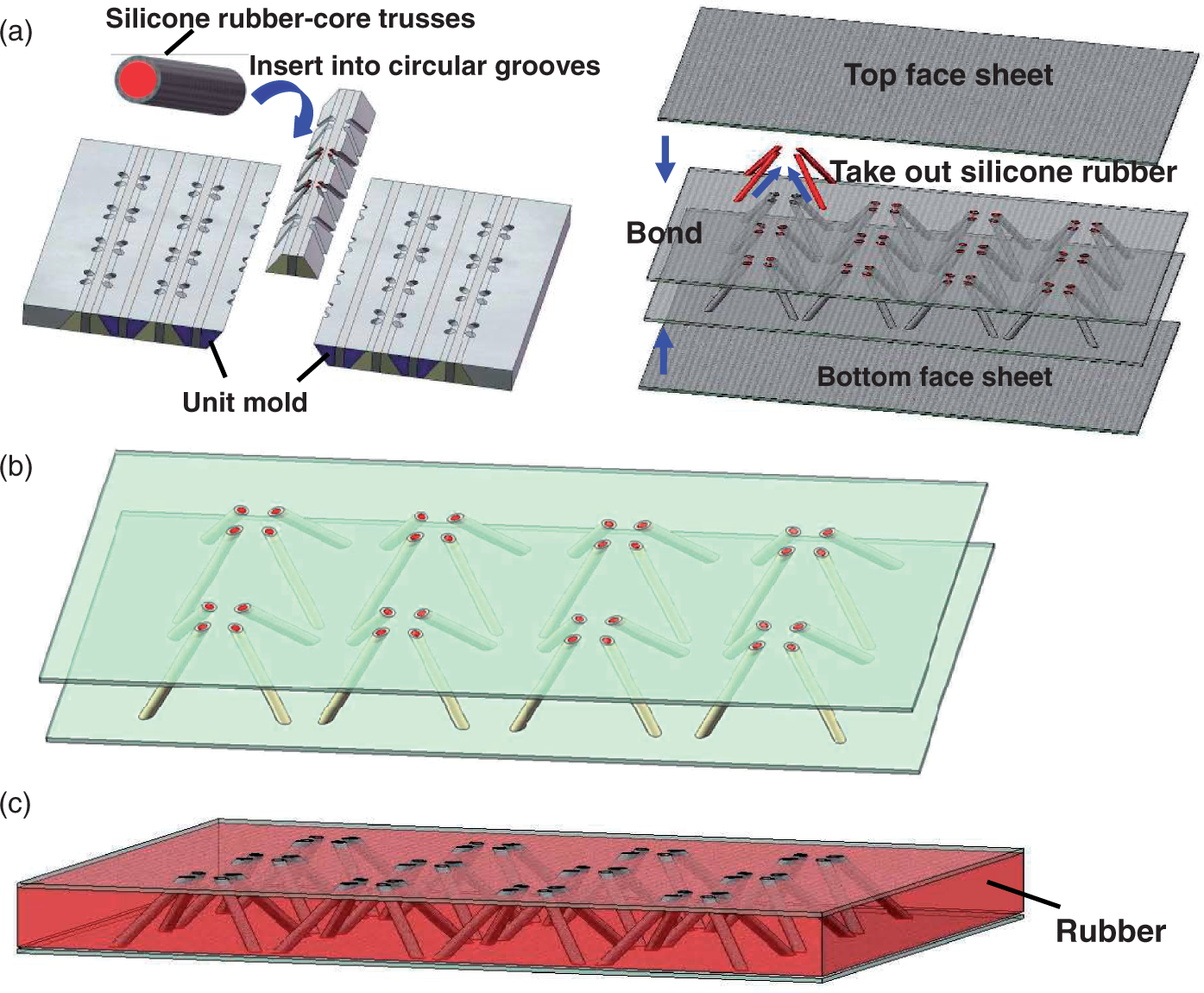
Filling inside trusses. This approach forms hybrid truss CPL construction which has been discussed in ref.
14
The static compressive stress of a hybrid CPL structure can be written as

Filling inter-truss space. In this approach, we exploit the inter-truss volume inherent in cellular truss structures. Liquid silicone rubber was perfused into the lattice structure (outside the trusses) and the assembly was held at 20℃ for 24 h to cure the rubber. The space-filled lattice structure is illustrated in Figure 1(c), and the corresponding compressive stress can be expressed as


Summary of the parameters for sandwich structures.
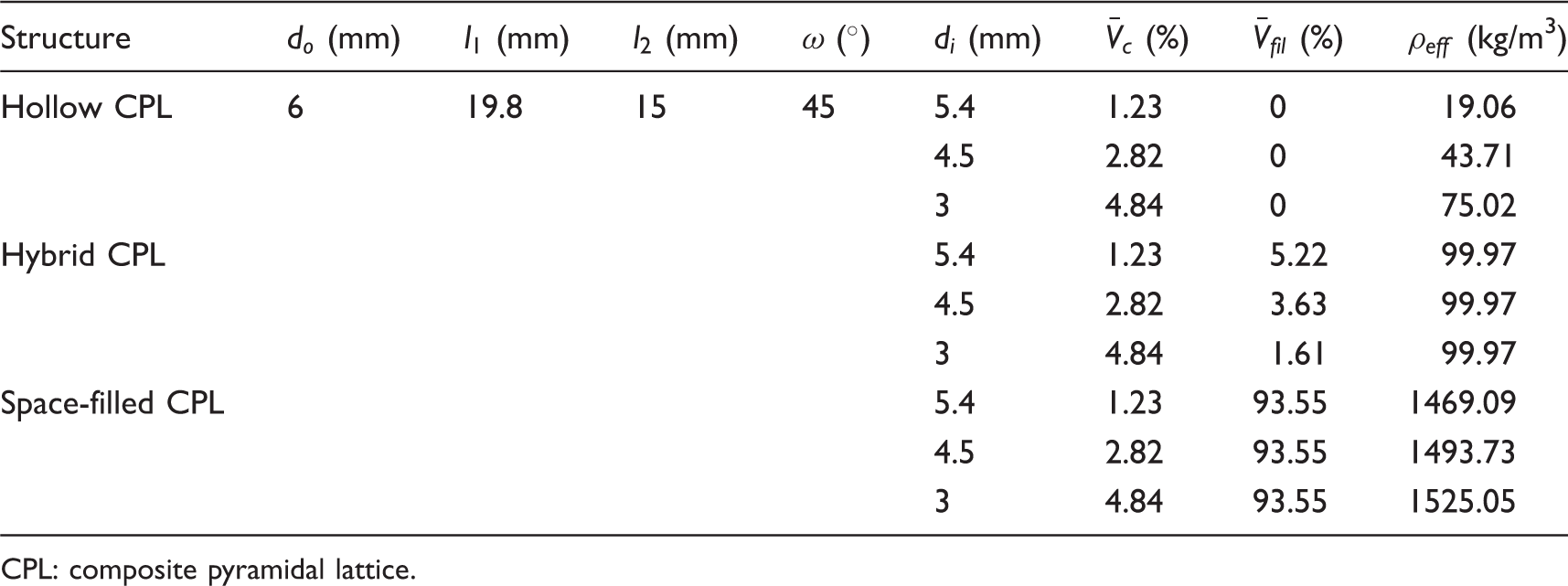
CPL: composite pyramidal lattice.
The compressive behaviors of all the structures including bulk silicone rubber are summarized and are plotted in Figure 2, and are compared with those predicted by the formula above. Note that the compressive behavior of rubber in Figure 2 was obtained by compressing a fully free bulk rubber without any constraint. The experimental curves of the structures indicated that filling rubber change little of the compressive strength. However, the stress of rubber-filled structures increases with the strain after the peak which is different from the response of hollow CPL structures. The theoretical prediction was well matched with experimental curves before the peak stress, but became less than experimental stress after the maximum stress attained. The deviation was attributed to the interaction between the truss shells and filling rubber during the prediction.
Behavior of all the structures including bulk silicone rubber, compared with theoretical prediction.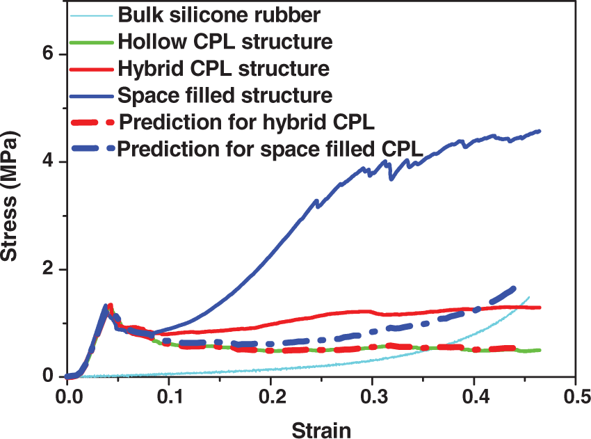
Damping behavior
Vibration tests
All CPL sandwich samples with and without filling rubber composed of two 200 × 150 mm face sheets with stacking sequence of [0/90/0/90]s and 3 × 4 pyramidal unit cells were employed in vibration tests. All specimens were tested under free–free boundary conditions, obtained by suspending the panels with thin nylon strings. Impulse response vibration measurements were assessed using a signal analyzer (Nicolet Compass Dynamic Signal Analyzer) as shown in Figure 3(a). A slight hammer tap used to excite the specimens and the response was detected by a miniature accelerometer (B&K8903) attached to the specimen with adhesive. A conditioning amplifier (YE5853) was used to provide power to the accelerometer and amplify signals from it. The transient response for the CPL structures with and without silicone rubber at the same position is compared.
Experiment set-ups for (a) vibration and (b) low-velocity impact tests.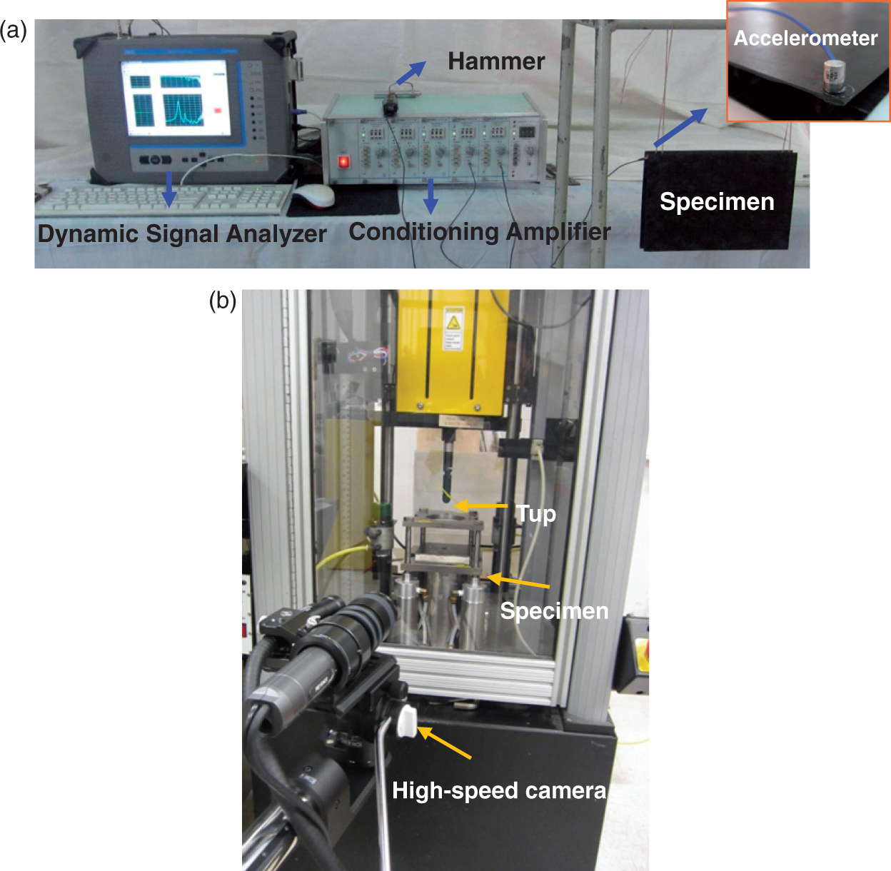
Damping properties
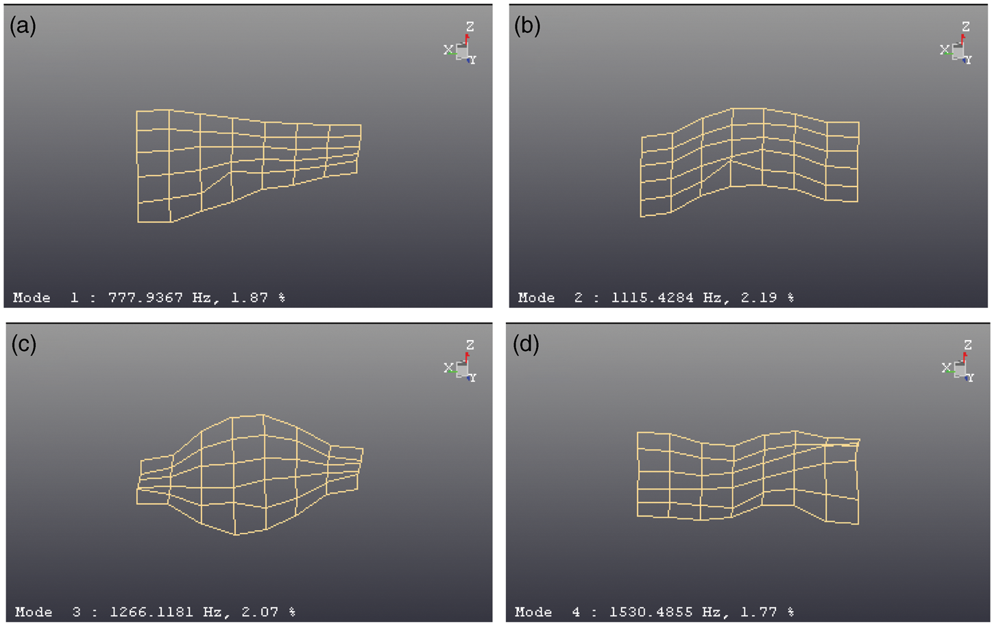
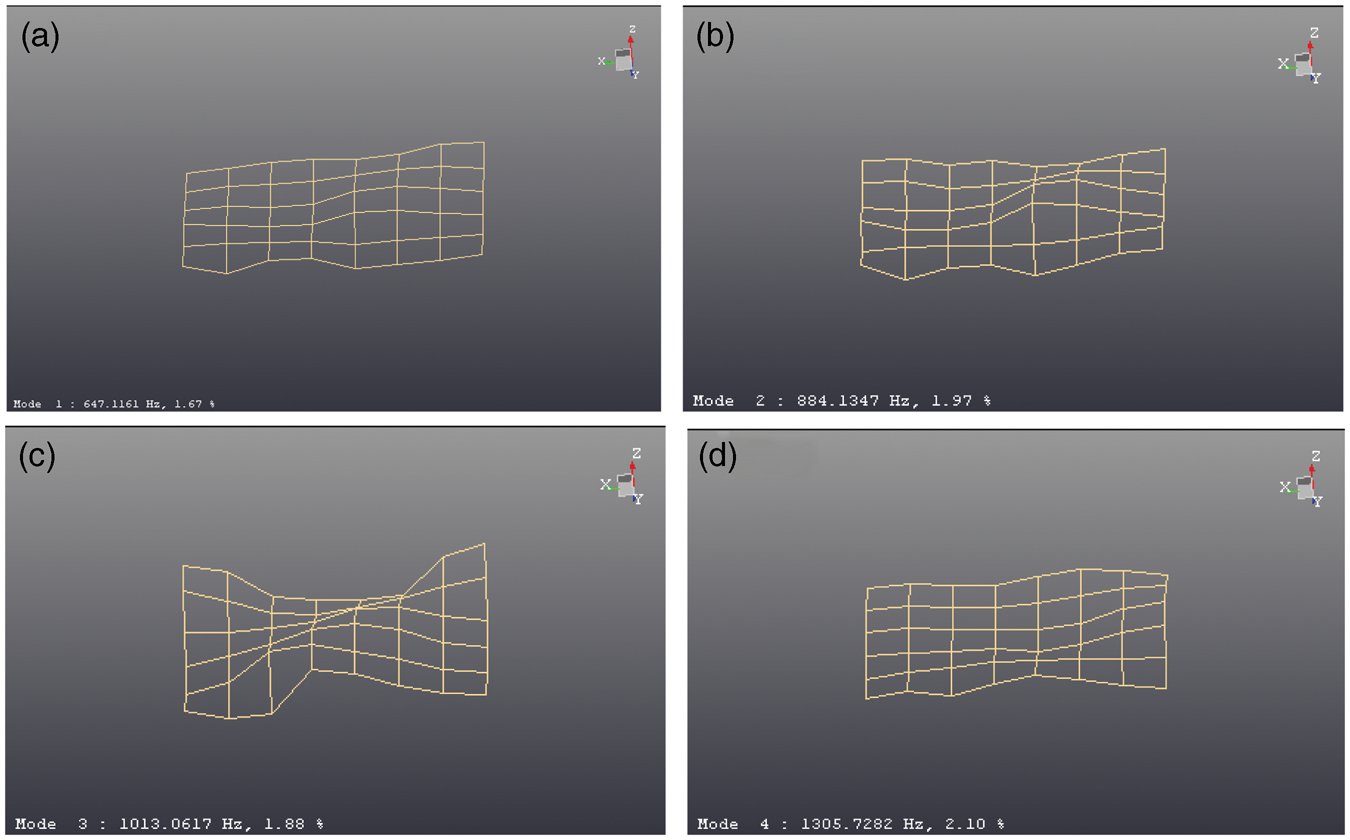
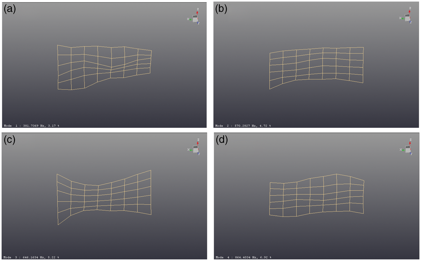
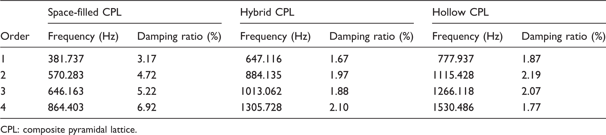
The transient acceleration response for CPL structures with and without rubber filling is shown in Figure 4. Vibration modes for the first four orders are shown in Figures 5–7 for CPLs with and without filling rubber, respectively. The plot in Figure 4 clearly shows that relative to the hollow truss control structure, the decay rate is slower for hybrid CPL structures and faster for space-filled CPL structure. Note that the acceleration amplitudes for these structures differed, a consequence of slight differences in the input excitation signals imparted by the hammer, which were impossible to control. The frequencies and damping ratios for the first four orders of all the structures are shown in Table 2. The frequency of space-filled CPL is the lowest and the damping ratio is about two times that of hollow CPLs for the first three orders and four times for the fourth order. Obviously, the frequency decreases as the mass increases.
Transient responses of acceleration for hollow CPL structures with and without filling rubber. Vibration modes for hollow composite pyramidal lattice structures at the (a) first order; (b) second order; (c) third order and (d) fourth order. Vibration modes for hybrid truss composite pyramidal lattice structures at the: (a) first order; (b) second order; (c) third order and (d) fourth order. Vibration modes for space-filled composite structures at the (a) first order; (b) second order; (c) third order and (d) fourth order. Frequencies and the corresponding damping ratio of hollow, hybrid and space-filled CPL structures with truss inner diameter di = 5.4 mm. CPL: composite pyramidal lattice.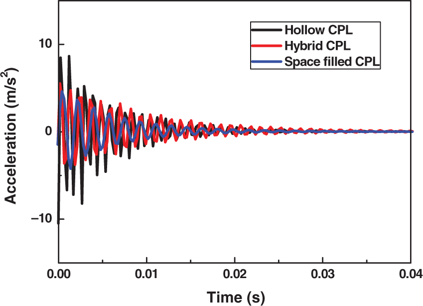
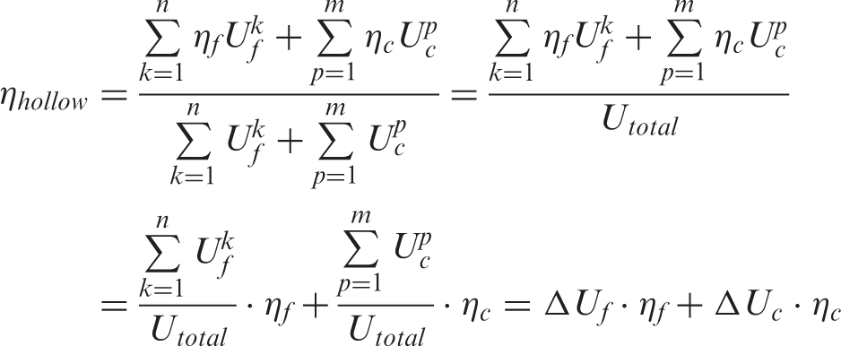
The damping ratios of hybrid CPL structures decreased by 0.2% for the first order and the acceleration decayed more slowly than that of the hollow CPLs. Theoretical analysis was carried out to explain this phenomenon, by deducing the effective damping ratio based on modal strain energy method. The damping ratio of hollow CPL structures can be expressed as
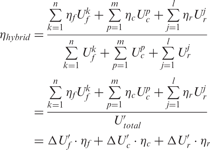
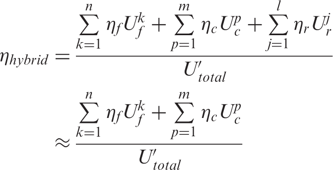
Similarly, for hybrid CPLs, the effective damping ratio is expressed as
Low-velocity impact behavior
Low-velocity impact tests
Low-velocity impact tests were performed using drop tower (INSTRON Dynatup 9250HV) as shown in Figure 3(b). The impact machine was equipped with a hemispherical tup with the capacity of 15.56 kN to record transient force. Using data acquisition system, load versus time data for each test was recorded, and the deflection, specimen velocity and energy absorbed by the specimen were measured. The mass of the crosshead was maintained at 6.33 kg. Impact height was adjusted by the desired energy level. Samples for impact tests were composed of two 100 × 100 mm face sheets with stacking sequence [0/90/0/90]s and 2 × 2 pyramidal unit cells, and divided into three groups according to different truss inner diameters of 5.4 mm, 4.5 mm and 3 mm. All specimens were fixed in the pneumatic clamping system with inner ring diameter of 76.2 mm and impacted at a pyramidal node. Each group consisted of three kinds of structures: hollow, hybrid and space-filled CPL structures. Samples were subjected to impact at 30 J (5.4 mm), 20 J (4.5 mm) and 40 J (3 mm), respectively. A high-speed camera (Keyence VW-6000) was used to record the transient behavior of the specimens during impact tests.
Ultrasonic scanning
Ultrasonic inspection of lattice structures after impact was carried out by ultrasonic imaging (ULTRAPAC II, Physical Acoustics Corporation). The components of the system include a computer-controlled ultrasonic detector, an immersion ultrasound transducer of 10 MHz, a water tank, a transducer gantry with stepper motors and control/acquisition software. The scanning was performed in the pulse-echo immersion mode and the gate was set on the adhesive surface echo of the upper face sheet facing the sensor. A 70 × 70 mm area around the impact site was scanned and damage areas of different structures were compared from the c-scan images.
Low-velocity impact resistance
Impact hollow CPL structures
The load–time, energy–time and load–deflection curves for hollow CPL sandwich structures at different impact energy levels are shown in Figure 8 (a) to (c). There is only one peak for both load–time and energy–time curves at impact energy levels 20 and 30 J and the corresponding closed load–deflection curves include a region of ascending load and a descending section combining loading and unloading. At an impact energy of 20 J, the descending section in load–deflection response represents the rebounding of the impactor from the specimen. At an impact energy of 30 J, the load fluctuates at the peak and the descending section reflects partial softening of the specimen and partial rebounding of the impactor. The structural response differs markedly for an impact energy level of 40 J, the response is different. Two peaks appear in the load–time curve, indicating that the impactor has perforated the upper face sheet and the load has transferred to the truss core. Thus, the absorbed energy increases again as shown in Figure 8(b). There is no visible damage to the lattice members. However, the load resistance of truss core will play an important role once the load transfers to the truss core.
(a) Load–time; (b) energy–time and (c) load–deflection curves for hollow CPL sandwich structures with truss inner diameters di = 4.5, 5.4 and 3 mm impacted at the corresponding energy levels 20, 30 and 40 J; visual damage at the surface and ultrasound images inside the face sheet (adhesive layer) after impacting at (d, g) 20 J; (e, h) 30 J and (f, i) 40 J.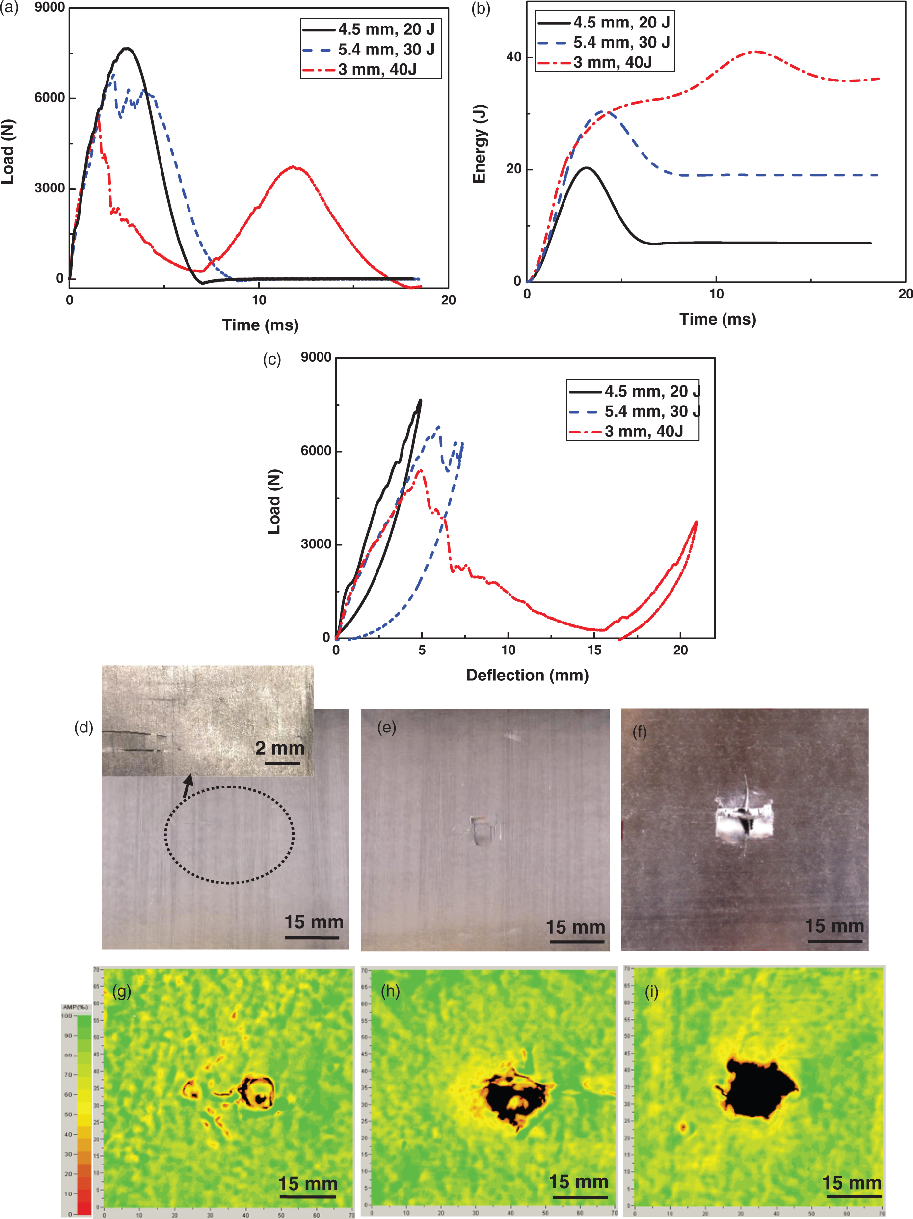
The visual damage on the top surface for all hollow CPL sandwich structures impacted at different energy levels are shown in Figure 8(d) to (f) while the corresponding ultrasonic scanning images are shown in Figure 8(g)–(i). The black area representing no reflection and thus complete break of material is about 25 × 20 mm2 in Figure 8(i) and becomes the largest in the case of high-energy impact when the impactor penetrates the face sheet. Because the gate was set on the adhesive surface echo of upper face sheet, the c-scan images, reflecting the damage areas inside the upper face sheet, are larger than the visual images. The damage will spread during the impact process.
Impact rubber-filled CPL structures
The hybrid and space-filled CPL structures with truss inner diameter of 4.5 mm were tested at an impact energy level of 20 J and compared with the response of hollow CPL structures. The load and energy versus time and load–deflection curves are shown in Figure 9(a)–(c). There is negligible difference among the three kinds of structures. In Figure 9(c), the closed curve and the pure rebounding of the impactor (deflection to zero) indicate no penetration of the specimen. This is also evident in the images captured by high-speed camera in Figure 10. The impact energy 20 J caused little damage and the trusses did not collapse. Visible cracks appeared in the upper face sheet of these sandwich structures, muck like that of hollow CPL shown in Figure 8(d) and thus the visual images are omitted here. The damage areas (black) of the filled CPL structures shown in the ultrasound C-scan images in Figure 9(d) to (e) are limited around the contact zone. The broken portion (black area) of the space-filled structure is smaller although the overall damage area (12.5 × 10 mm2) is greater than that of hollow or hybrid CPL structures (about 8 × 10 mm2), indicating the damage spreads broader which is actually a phenomenon for great energy absorption materials.
(a) Load–time; (b) energy–time and (c) load–deflection curves for filled CPL structures with truss inner diameter di = 4.5 mm at impact energy level 20 J compared with those of hollow CPL structures; ultrasound images of damage areas inside the face sheet (adhesive layer) for (d) hybrid CPL structure and (e) space-filled CPL structure. Note that the visual images illustrating damage for hybrid and space-filled CPL structures are similar to those of hollow CPL structure as shown in Figure 5(d). High-speed images for hollow CPL structure with truss inner diameter di = 4.5 mm at impact energy 20 J.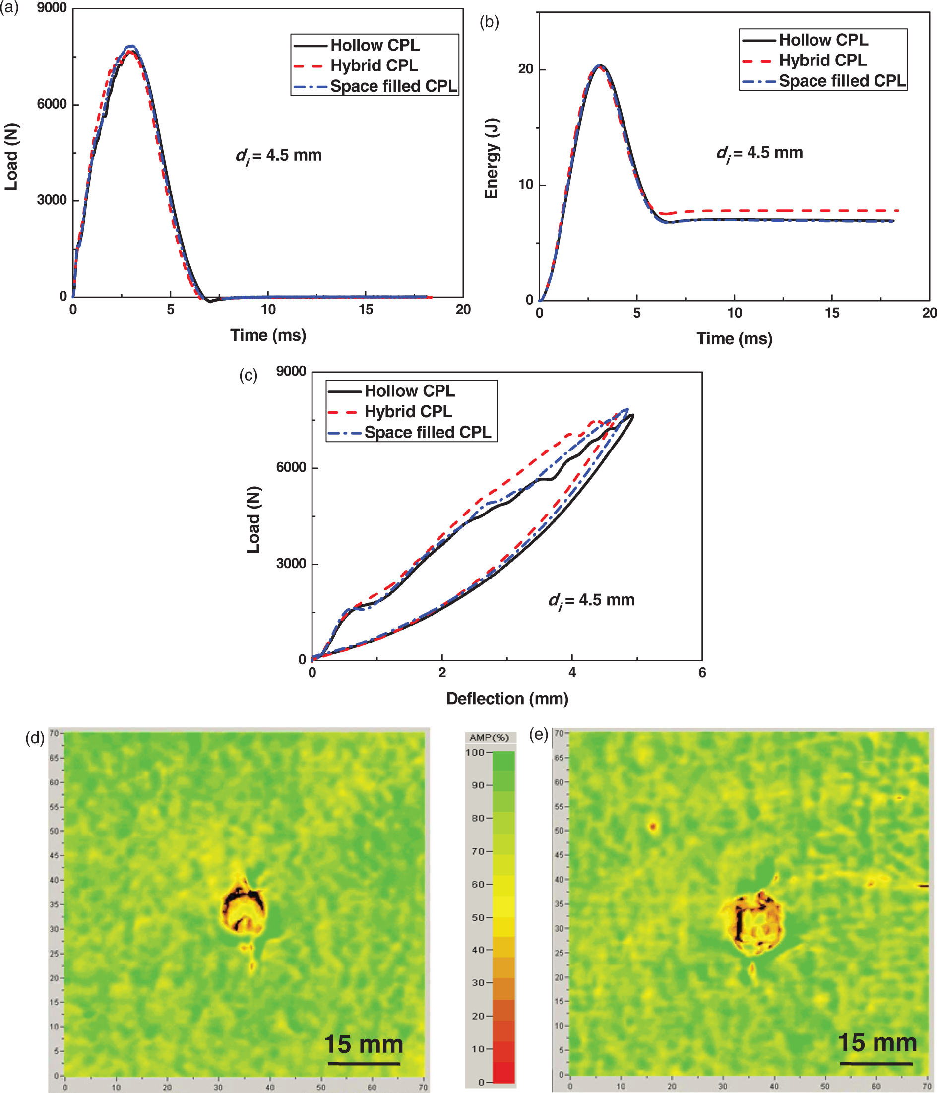
Filled CPL structures with truss inner diameter of 3 mm were subjected to 40 J impact and the dynamic response is shown in Figure 11(a) to (c). Two peaks appear in the load–time curves, although the second peak is subtle (Figure 11(a)). The absorbed energy of hybrid CPL structure is greater than that of hollow CPL structure until the force transfers to the truss core and the energy increases quickly again as shown by the bold line in Figure 11(b). Further rising of energy after perforation for hollow CPL is attributed to the resistance of the truss core against impact, while hybrid CPL exhibits a relatively flat curve after perforation demonstrating the increased impact resistance. For the space-filled CPL structures, the closed load–deflection curve indicates that the indentor does not fully penetrate the face sheet, and thus rebounds during the descending portion of the curve.
(a) Load–time; (b) energy–time and (c) load–deflection curves for filled CPL structures with truss inner diameter di = 3 mm at impact energy 40 J compared with those of hollow CPL structures; ultrasound images of damage areas inside the face sheet (adhesive layer) for (d) hybrid CPL structure and (e) space-filled CPL structure.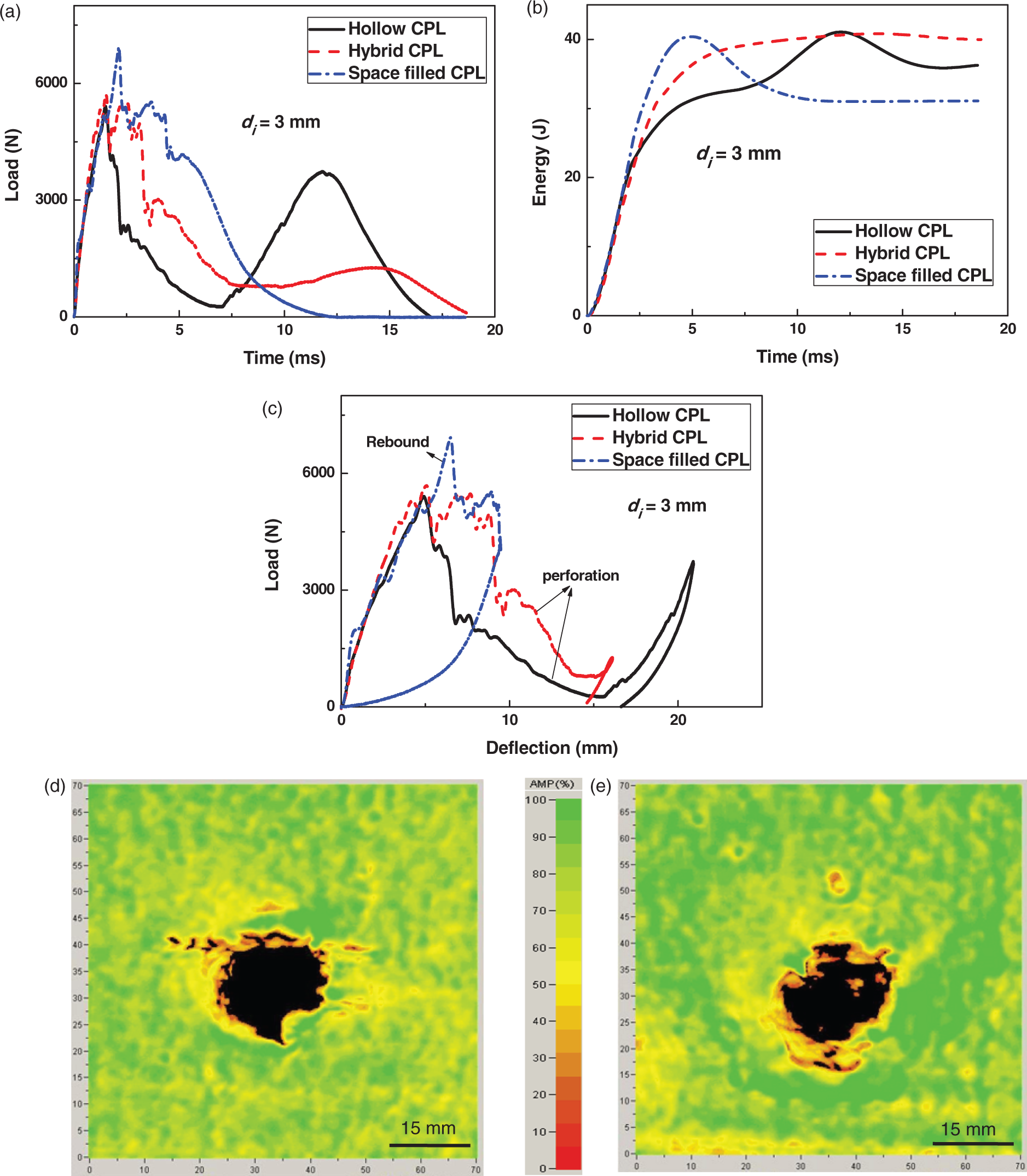
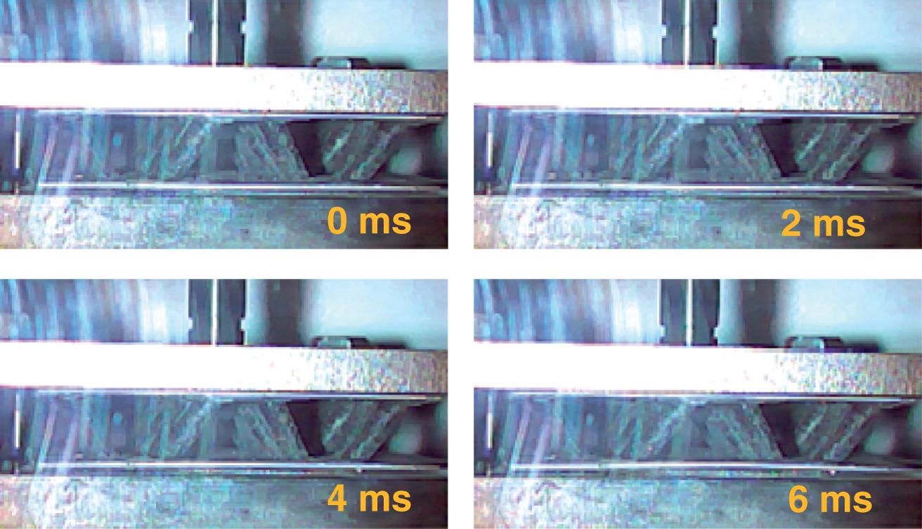
The ultrasonic images of filled CPL structures are shown in Figure 11(d) and (e). The damage area of perforated hybrid CPL is comparative with that of hollow CPL, while that of space-filled structures is also nearly the same as that of hybrid or hollow CPL structures although the impactor does not perforate the face sheet. Images recorded by the high-speed camera were shown in Figure 12 for hollow CPL structures with truss inner diameter di = 3 mm at impact energy 40 J. The white triangle traces the position of the indentor, which shows the path of perforation and rebound.
High-speed images for hollow CPL structure with truss inner diameter di = 3 mm at impact energy 40 J. Note that the white triangle traces the position of the indentor.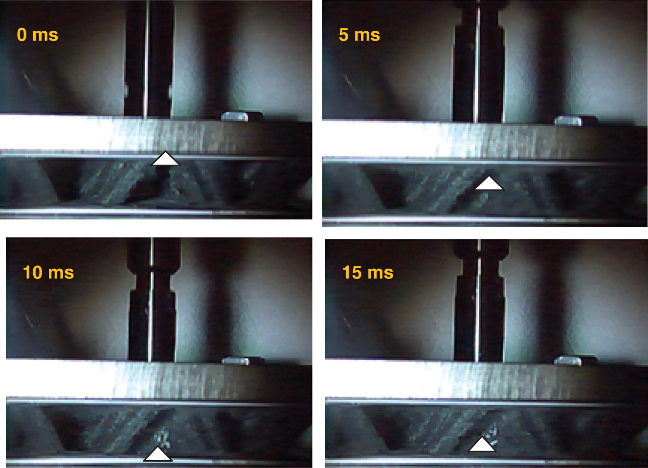
Summary and conclusion
Hybrid and space-filled CPL structures were built by filling silicone rubber within and between truss members, respectively. Dynamic properties were evaluated with vibration and impact tests for the filled CPL structures. The damping ratios by vibration tests were compared with those of hollow CPL structures: (1) for the space-filled CPL structures, the damping ratios increased about two times that of hollow CPLs for the first three orders and four times for the fourth order and (2) the damping ratios of hybrid CPL structures decreased by 0.2% for the first order. We attributed the unexpected behavior of hybrid CPLs to the low strain energy contribution of rubber inside the lattice members.
As tested in low energy level, the broken portion (black area) of the space-filled structure is smaller although the overall damage area (12.5 × 10 mm2) is greater than that of hollow or hybrid CPL structures (about 8 × 10 mm2). Furthermore, as impacted at higher energy, the rubber filling within the trusses increases the crushing resistance of the truss core while filling between the trusses can prevent the penetration of the tup. Perforation energy is different for different structures. Generally, the impact resistance is higher for structures with stronger truss cores, or structures filling with more rubber. Finally, the energy absorption capability of filled CPL structures increases.
The present study further examines two hybrid concepts: hybrid truss and space filling. Hybrid truss concept is inspiring because it can introduce function while retaining the space for other use. However, the realization of functionality requires analysis and design, which probably depends on the selection of truss geometries and properties of filling materials. For space filling concept, the filling materials are preferred to be liquid before curing, such as rubber or polymer, which are easier for perfusion. Otherwise, shaped bulk material, such as triangular ceramic, will be required to insert into the truss cores. Silicone rubber in the present study is just an illustration showing the hybrid idea accompanying with the fabrication feasibility. The present structures should be relevant for a range of applications, including damping vibration attenuation structures and crashworthy vehicles. Other functionalities can be attained similarly.
Footnotes
Funding
The present work is supported by NSFC (11172080 and 90816024), 973 Program (No.2011CB610303). SN gratefully acknowledges support from the Gill Composites Center. SY also acknowledges the support of Most Potential New Scholar Prize awarded by Ministry of Education in China
Conflict of interest
None declared.