
Abstract
The potential of accurate modelling of the shear modulus reduction of laminates with cracked 90-layers using models based on the minimization of the complementary energy with improved stress description in the constraint layers is evaluated.
This group of models refine Hashin’s model by introducing shape functions with unknown parameters to represent the out-of-plane shear stress distribution across the constraint layer thickness. The Hashin’s model becomes a particular case of the presented when the shape parameter approaches to zero. The most accurate shape parameters are found in the result of minimization. Three models are compared: the present variational model, Hashin’s model and the shear lag model introduced by Soutis which assumes linear out-of-plane shear stress distribution over an unknown part of the layer. It is shown in this paper that the size of this part may be determined by minimization of the complementary energy. The present model is the most accurate amongst the three, whereas Soutis’ model is more accurate than the Hashin’s model for laminates with constraint layer, thicker than the cracked layer. The comparison with finite element method results shows reasonable agreement. Agreement can be improved developing models with better description of the stress state in the cracked layer.
Introduction
In laminated composite materials, many different types of micro-damage entities may evolve without causing final failure of the structural element. However, they are responsible for stiffness reduction and initiating of other, more critical, damage modes. One of the first and most common damage mode in laminates, causing degradation of thermo-elastic properties, is intralaminar cracking in layers with off-axis orientation with respect to the main loading direction. Large amount of experimental data has been gathered regarding the reduction of the elastic modulus and Poisson’s ratio of damaged laminates. Numerous models based on analytical approaches and/or numerical routines have been developed to study the relationship between the damaged state and the modulus of the laminate.
The situation is entirely different regarding the in-plane shear modulus of the damaged laminate. Only a few experimental investigations are described in the literature and often the data are not reliable. For example, Tsai et al. 1 developed a methodology for shear modulus determination using an experimental set-up where a laminate pre-damaged in tension is subjected to in-plane tangential displacement in the middle part. The shear modulus was calculated using a Timoshenko beam approximation. The problem, in general, is that it is difficult to introduce intralaminar cracks in a controlled way during the shear test. Cracks have to be introduced, for example, during a tensile test with transverse tensile stress in layers. Unfortunately, the requirements on specimen geometry in tension and in shear are not compatible.
Another problem of using experimental data for model validation is related to the non-linear stress–strain response to shear of unidirectional (UD) composites. For a layer in the laminate, this response is non-linear not only because of the evolving damage state, but also because of non-linear viscoelastic and viscoplastic effects. 2 For the above reasons, analytical model predictions are usually validated compared with the results of numerical solutions.
Hashin 3 used the principle of minimum complementary energy. The admissible stress field, which satisfies equilibrium as well as the boundary and interface conditions in tractions, was constructed assuming that the in-plane shear stress distribution across each ply thickness is uniform and the single unknown function describing the in-plane shear stress distribution depends on the distance from the crack only. Using the stress distributions obtained by minimization, the lower bounds for the shear modulus of the laminate were obtained.
Two entirely different approaches were used1,4–7: (a) Tan et al.4,5 obtained expressions for axial modulus, Poisson’s ratio and shear modulus of the cross-ply laminate with 90-cracks, by integrating the equilibrium and constitutive expressions over the ply thickness and obtaining a second order differential equation for stress distributions; (b) Tsai et al.1,6 and Abdelrahman et al. 7 reduced the 3-D elasticity problem to 2-D problem in terms of displacements 1 or stresses 7 averaged over the ply thickness. In both cases, the obtained set of differential equations with constant coefficients was solved analytically. Due to the assumed linear through the thickness dependence of the out-of-plane shear stresses, the results of these models coincide with Hashin’s result.
Henaff-Gardin et al. 8 analysed a double-cracked cross-ply laminate in a similar manner as in Ref. 1 just using a simpler shear lag model with parabolic opening displacement and uniform sliding displacement distributions. For the same problem, Kashtalyan et al.9,10 adjusted the effective properties of the constraint layer for damage when analysing the local stresses in another layer. This leads to an iterative procedure when cracks are present in both 0- and 90-layers of the cross-ply laminate. It was shown that the interaction of cracks in two layers leads to considerable additional reduction of the laminate’s shear modulus.
Fan et al. 11 presented constitutive equations for a layer with cracks containing the so-called ‘in-situ damage effective functions (IDEF)’ which depend on the crack density of the lamina and on the neighbouring layer constraints. In order to determine IDEF, they introduced ‘an equivalent constraint model’, which assumes that the constraint of the lay-ups above and below the analysed lamina is the same as from two homogenized orthotropic sublaminates and the actual laminate was replaced by a cross-ply. The constitutive relationships for the damaged layers were used in the framework of the CLT to obtain the stiffness matrix of the damaged laminate.
This approach was further refined by the Soutis research group 12 where the local stress problem was solved using an improved shear lag model which assumed that the intralaminar shear stress in the 0-layer differs from zero only in a zone close to the interface. This idea which is supported by finite element calculations was not consistently implemented: in Ref. 12, the authors claimed that the perturbation zone covers one prepreg layer, whereas in more recent publications9,10,13 they are extending the perturbation zone over the whole homogenized sublaminate. Obviously, the problem is that the size of this zone becomes a fitting parameter.
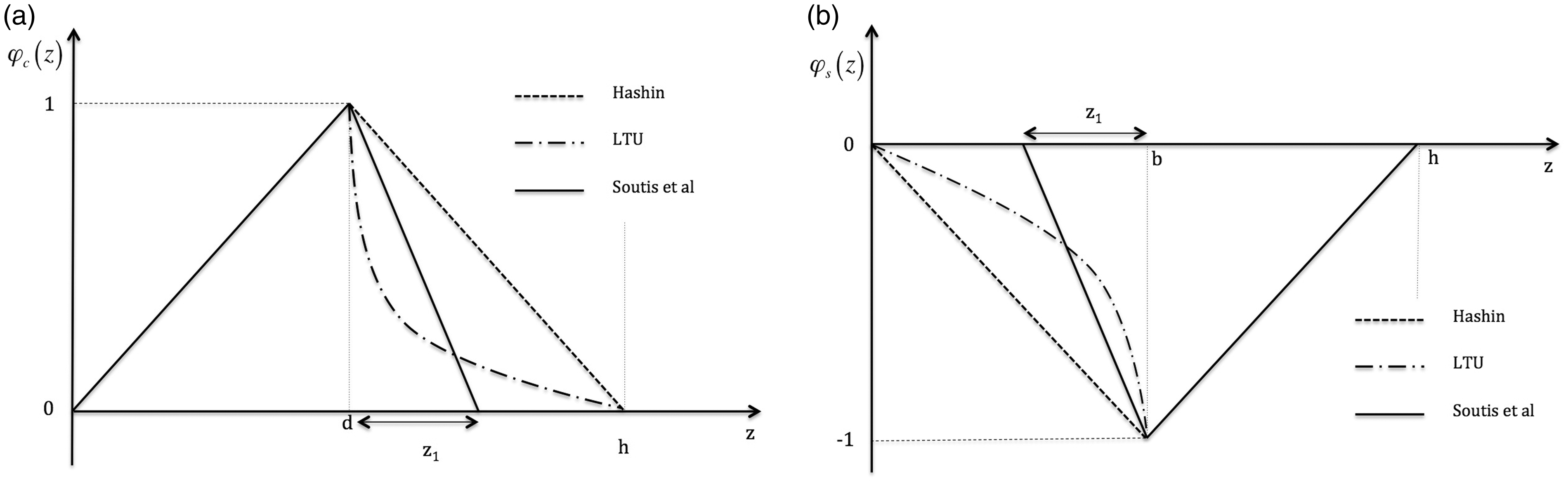
Their hypothesis that the out-of-plane shear stress in the constraint layer can be described by a decreasing linear function of the distance from the interface (the maximum is at the interface and the value is zero at distance z1) will be inspected in this paper. To find z1, a simple calculation routine based on the principle of minimum complementary energy will be described and used.
The objective of the current work is to address the potential of improving the conservative predictions for [S/90n]s and [90n/S]s laminates using variational models with more refined stress description in the constraint layer. A more general variational model is introduced to predict shear modulus reduction of laminates with intralaminar cracks. This model includes Hashin’s model as particular case and can be used to find the shear zone size in the model based on Soutis assumptions. In contrast to Hashin’s model, which assumes linear distribution, the novel model allows an arbitrary shape of the out-of-plane shear stress distribution in the constraint layer. Selecting a specific form of the shape function with unknown parameters, the principle of the minimum complementary energy can be used to find these parameters. The bilinear distribution 12 is one particular case considered and the shape parameter to find is z1. The most accurate model, between the ones that were compared, can be identified by comparing the complementary energy values at the minimum; the lowest value corresponds to the most accurate stress distribution. It is shown that the improved stress description in the constraint layer is not sufficient for accurate predictions of the laminate shear modulus. The approach for further improvement of the model is outlined.
Repeating element and assumptions
Model formulation
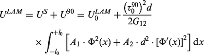
We consider a repeating element of the [S,90n]s or [90n S]s laminate with a periodic system of cracks in the 90-layers as shown in Figure 1. S is the notation used for the homogenized adjacent lay-up. Its elastic properties are as for a balanced ‘sub-laminate’ with the same lay-up. For simplicity and in order to maintain symmetry, with respect to the mid-plane, we assume that the lay-up of the sub-laminate on the top and on the bottom of the 90-layer is the same. In the simplest case, the sublaminate is a UD 0-layer. The crack spacing is noted as Intralaminar cracks in symmetric and balanced laminates. (a) [S/90n]s laminate with cracks in central 90-layer and (b) [90n/S]s laminate with cracks in surface 90-layer.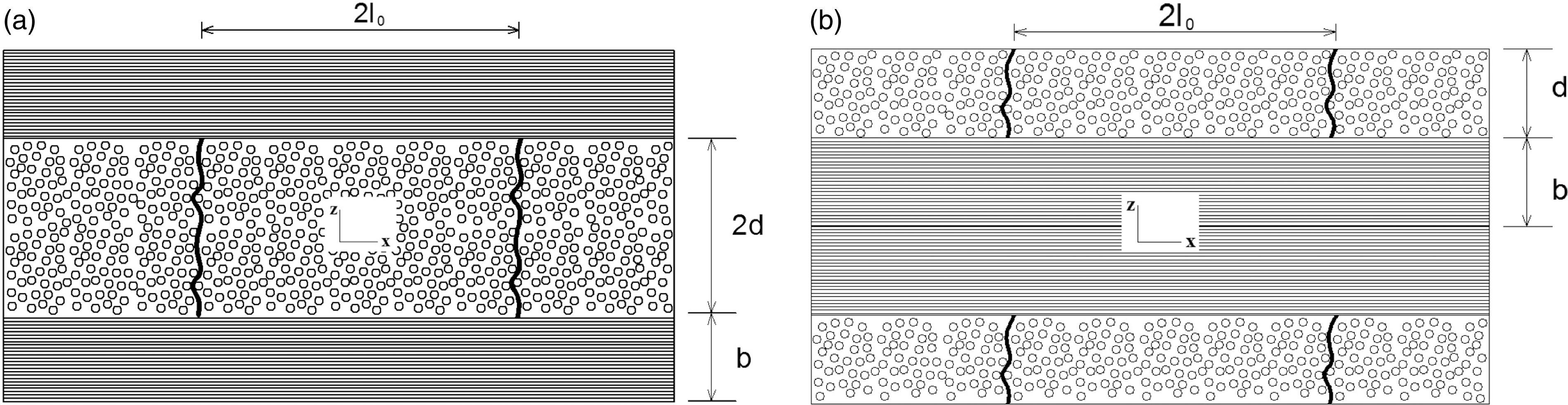

Assumed stress profiles
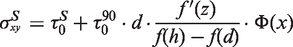
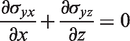
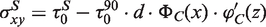
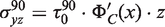
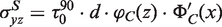
Independent on the location of the cracked 90-layer (on the surface or in the center of the laminate), we use the same assumptions and the same method of solution. It was shown in Refs. 3 and 14 that for the case when the stress distributions does not depend on the y-coordinate (infinite material in y-direction) the two stress components
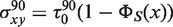
We assume that the in-plane shear stress in the cracked 90-layer,
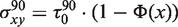
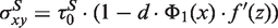
The shear stress in the 90-layer has to satisfy the traction-free condition on crack surfaces:

Expressions for stress components
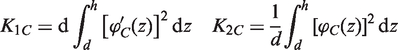
Cracked central 90-layer
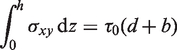
From the shear force balance

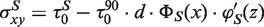
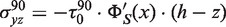
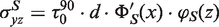
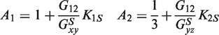
Cracked surface 90-layer
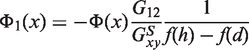
The derivation of expressions is very similar to the case of a central cracked layer and all stress components are expressed through unknown functions

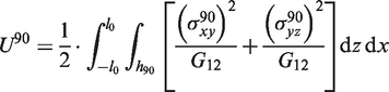
Minimization of the complementary energy
Thermal stresses do not affect the calculated elastic properties and therefore thermal terms can be neglected in the expression for complementary energy. The complementary energy expression becomes equal to the strain energy. In spite of this equality, there is a fundamental difference in using minimum principle for complementary energy and minimum principle for strain energy. In the former case, the used admissible stress field for minimization has to satisfy automatically the equilibrium conditions and all boundary and interface conditions in tractions, whereas in the latter case conditions of displacement continuity are automatically satisfied by the assumed functions. The strain energy of a repeating element between two cracks in 90-layer is

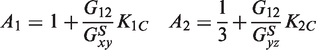
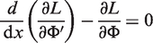
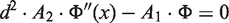
The function Φ that minimizes equation (25) has to satisfy the Euler–Lagrange equation (30):
Shear modulus expression
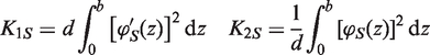
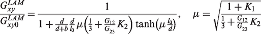
The shear modulus of the damaged laminate can be determined using
Selection of the shape function
Since it is expected that the shear stress perturbation in the sub-laminate will decay with increasing distance from the crack tip (layer interface), the absolute values of the
Exponential shape function
A natural choice with these features is exponential function. The shape function will contain one shape parameter α, which will be found as the one which produces the lowest value of the complementary energy given by equation (36). The expected shape is shown schematically in Figure 2 as ‘LTU’.
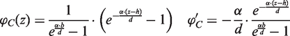
Central 90-layer with cracks
The shape function that satisfies boundary conditions in equation (17) is selected in the form:
Surface 90-layer with cracks
The shape function that satisfies the boundary conditions in equation (22) is selected in the form

Hashin's assumptions
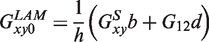
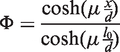
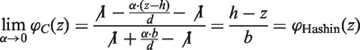
It can be proven that the Hashin’s solution
3
is a partial case of the selected functions (43) and (45). In Hashin’s model, the function
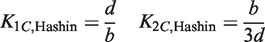
Bilinear shape functions by Soutis
In Ref. 12, the stress distribution in the 0-layers was assumed to be bilinear as schematically presented in Figure 2. The distance from the interface, where the stress perturbation becomes negligible, is denoted by z1. The shape functions for cracking in central and in surface 90-layers are

Results and analysis
Minimum of the complementary energy
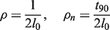
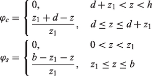
During the minimization of equation (36), the parameter α was increased with a small step and at each value the perturbation complementary energy (the second term in equation 36) was calculated. Since the minimum point does not depend on the applied stress and on the geometrical scale, this term was normalized dividing by Cross-ply laminate with 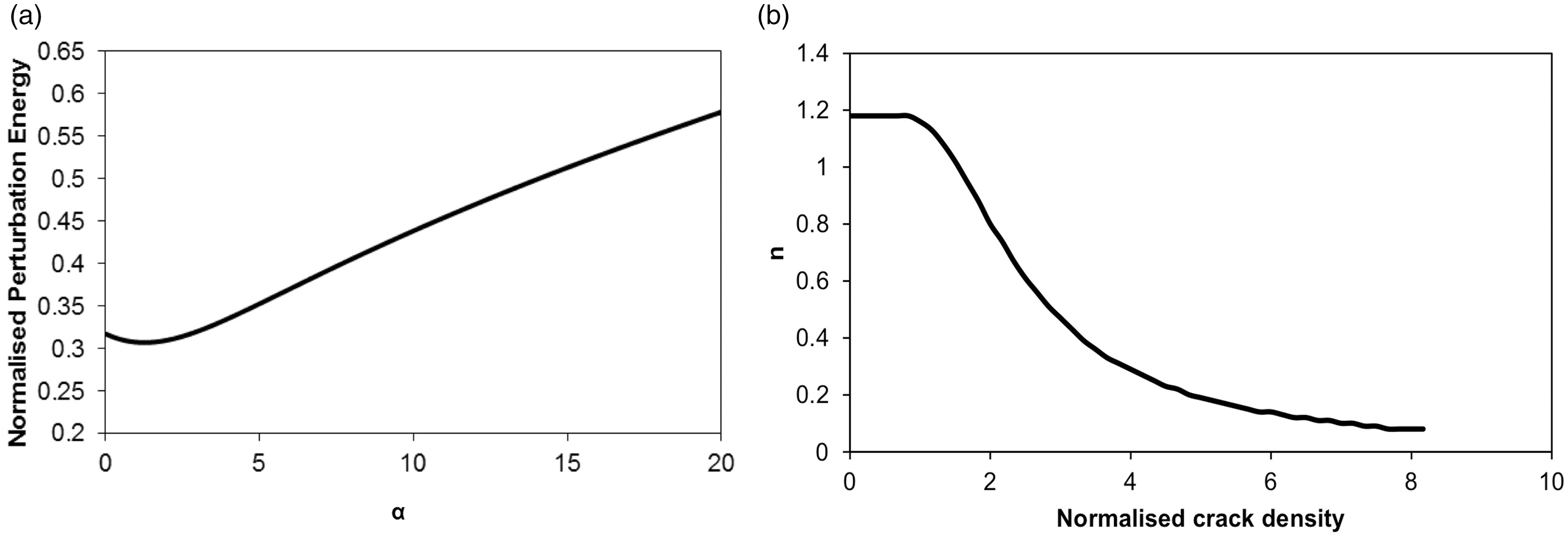
For very high crack density, the shear modulus from equation (40) has to approach to predictions of the ply-discount model, which assumes that transverse and shear modulus of the damaged layer is zero. One can show that it is possible only if the shape parameter
Comparison with Hashin’s model
The complementary energy, which was calculated by using the exponential shape function, was always lower than using Hashin’s model. As a consequence (a) the present model is more accurate for all geometrical and elastic parameters and (b) Hashin’s model predicts larger shear modulus reduction than the more accurate model.
However, as shown in Figure 4 for [S/90n]s laminates, the numerical differences in the predicted shear modulus are rather small. The well-known and expected trends shown in Figure 4 are as follows: higher shear modulus reduction when the cracked layer is relatively thick and the predictions are not sensitive to the layer shear modulus change of 20% or less (compare Figure 4(b) with Figure 4(c)); in the laminate, where the 0-layer is replaced by a sub-laminate with high in-plane shear modulus, the shear modulus reduction is much smaller. The comparison of the models for the cases presented in Figure 4 shows that (a) the improved model gives more noticeable difference for laminates with relatively thin cracked 90-layer; (b) the difference between models is slightly larger if the anisotropy in composite shear moduli increases, see Figure 4(b) and (c) (carbon fiber composites) and (c) for laminates with stiff sub-laminates, the difference is rather large in an intermediate crack density region.
Reduction of the shear modulus of a cross-ply laminate due to cracking according to Hashin’s and the present model. The upper index LAM is omitted. (a) 
Parametric analysis of the [0m/90n]s laminate using exponential shape functions
First, the thickness of the 0-layer was kept constant and equal to 0.3 mm and the thickness of the 90-layer was given different values. Specifically, values from 0.01–3 mm were studied with the step of 0.3 mm, i.e. the same as the assumed ply thickness. The values of the in-plane and out-of-plane shear modulus were kept constant as well; G12 = 3.4 GPa and G23 = 4.58 GPa. The results are presented in Figure 5. The arrow in Figure 5 indicates the direction of the 90-layer thickness increase; larger thickness leads to higher Effect of the 90-layer thickness on the shear modulus of the damaged [0/90n]s laminate.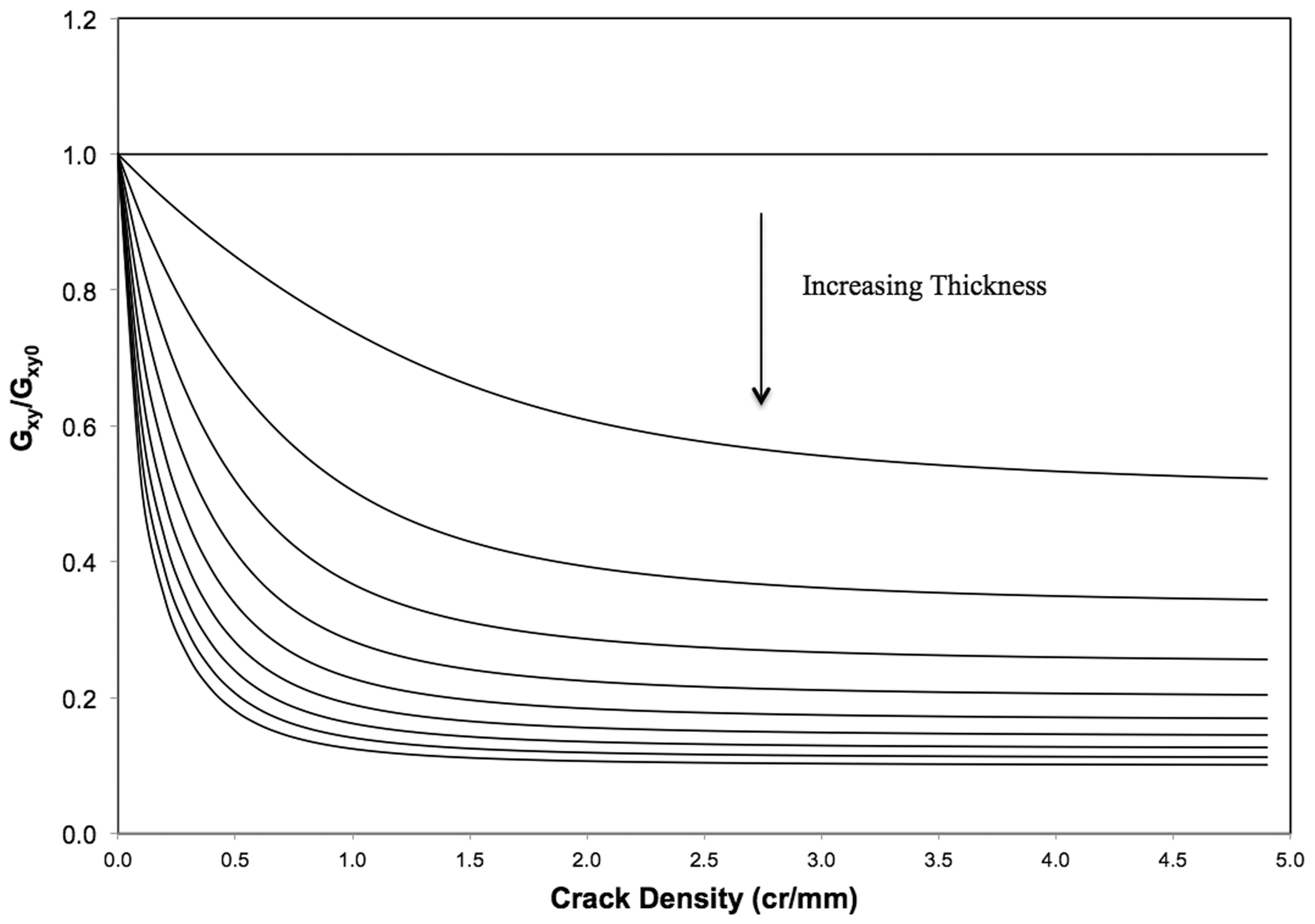
In order to quantify the effect of the thickness of the 0°-layer on the laminate’s shear modulus reduction, the thickness of the transverse layer was kept constant (0.3 mm) and the thickness of the 0-layer was given the values 0.01–3 mm with an increment of 0.3 mm. The results are presented in Figure 6. As expected from the ply-discount model, the thickness of the longitudinal ply has a strong influence on the final shear properties of the laminate: for 3-mm thick 0-layer, the modulus reduction is only 10% at saturation, whereas for 0.3 mm (i.e. only one 0-ply) the reduction is close to 53%.
Effect of the 0-layer thickness on the shear modulus of [0n/90]s cross-ply laminate.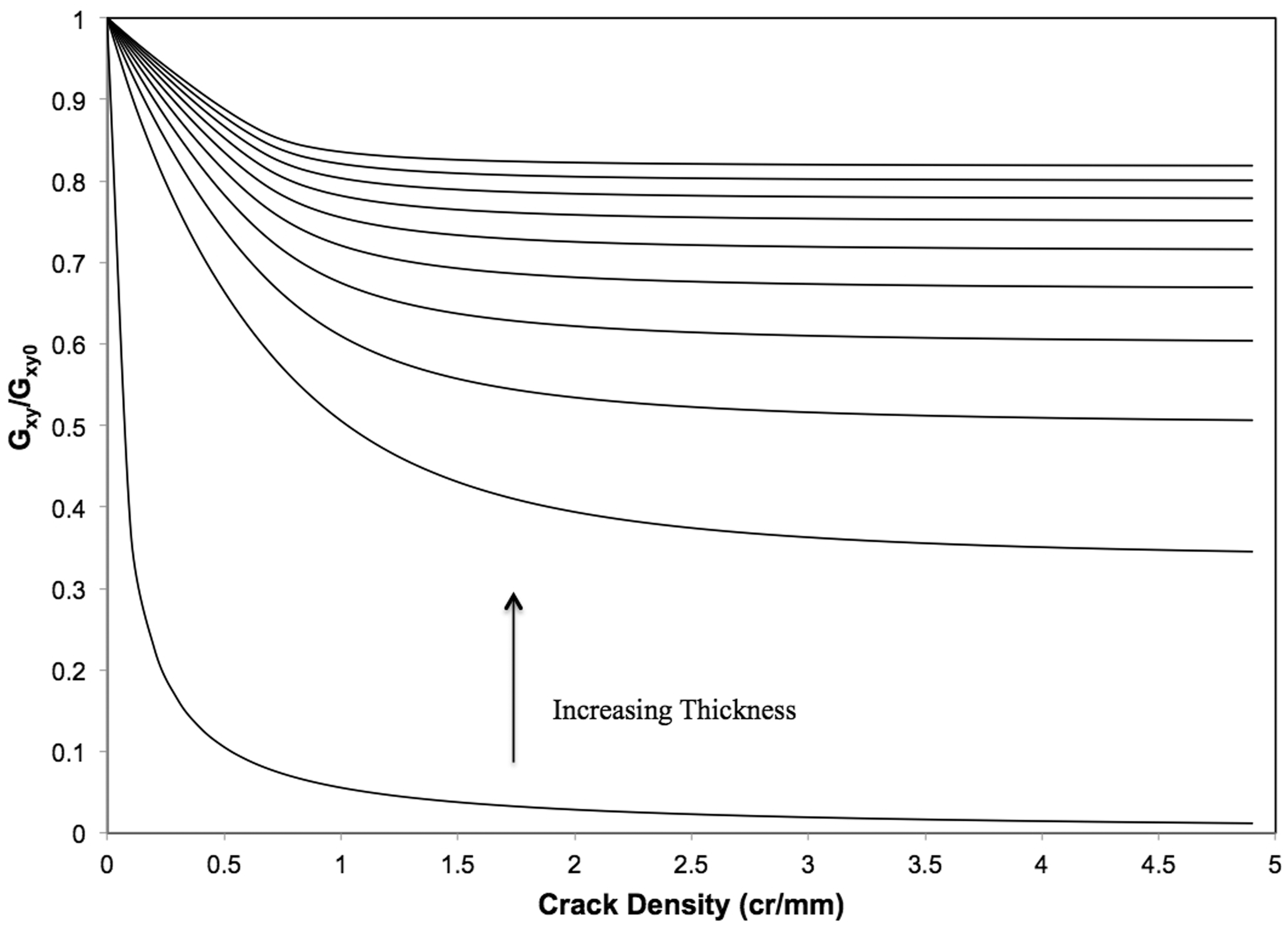
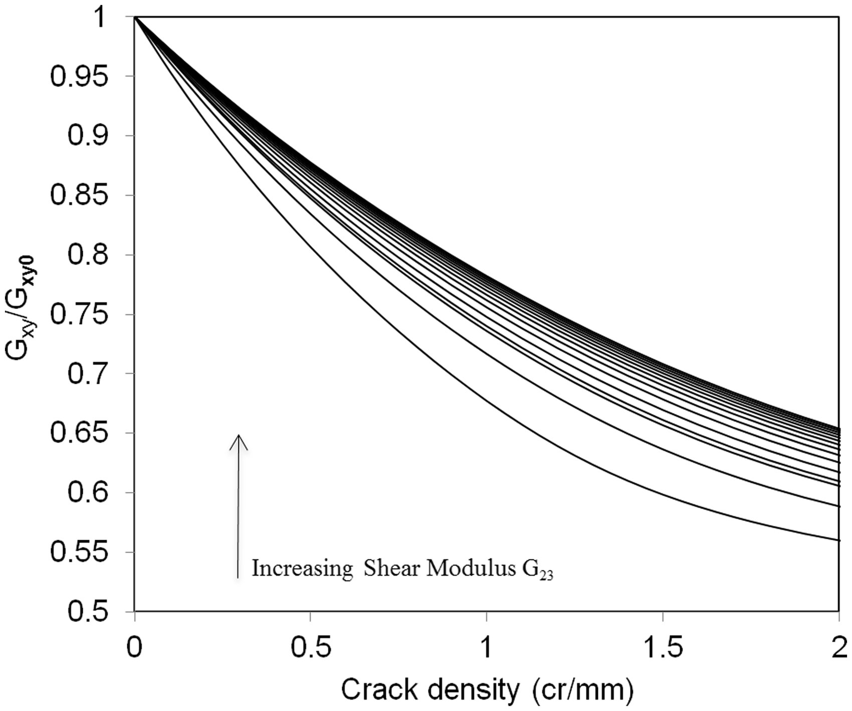
Apart from the geometrical parameters and the in-plane shear modulus, the current model contains the out-of-plane shear modulus G23 of the constraint layer as input. This property is usually not measured; it is estimated from the transverse isotropy if the constraint layer is a UD layer. The sensitivity of the results to the value of the out-of-plane shear modulus is shown in Figures 7 and 8. The geometrical parameters were kept constant (the thickness 0.3 mm for both 0- and the 90-layer) and G12 = 4.58 GPa. G23 was given values from 0.01–15 GPa. Figure 7 proves that for high crack density, the value of G23 is not of great importance (the curve approach to the ply-discount value calculated using CLT). Figure 8 is the detail of Figure 7 at more realistic, low crack density. With higher G23, the laminate’s shear modulus reduction versus crack density is much slower. This may be related to the decreased stress transfer length (size of the perturbation zone).
Effect of Effect of 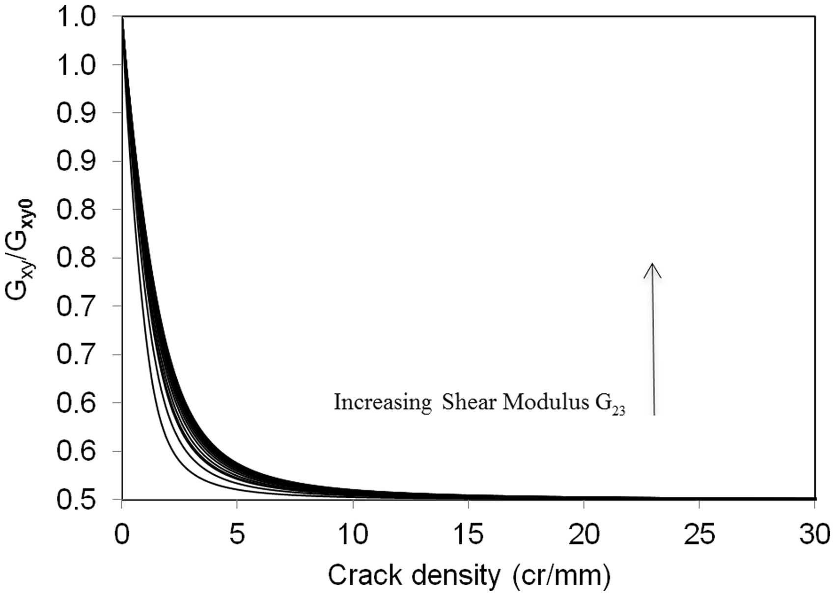
There was no need to perform parametric analysis for similar laminates with cracks in the surface layer; as shown in the section Exponential shape function
The conclusion that in both cases shown in Figure 1, the laminate’s shear modulus reduction with crack density is the same, was unexpected because the shape of the crack faces in the deformed state is different. The same result is obtained also for Hashin’s model (as a special case of our model) and also for Soutis model, see equation (51). Since this result could be due to the approximate nature of the discussed analytical solutions, results from finite element method (FEM), presented in
15
were used to resolve this question. More exactly, in Ref. 15 fitting functions for the normalized average crack face sliding displacement were presented in the form:
Comparison with FEM
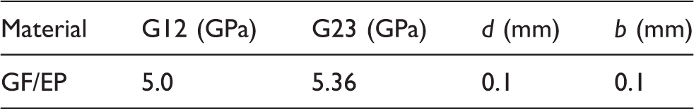
The shear modulus reduction for GF/EP laminate with layer elastic properties and geometrical parameters given in Table 1 was compared with results in Ref. 15 obtained using FEM. In calculations ANSYS 8.1 with 21,000 3_D 8-node elements representing the upper part of the repeating element were used (more details regarding boundary conditions, etc. are given in Ref. 15). The accuracy of the FEM model was confirmed by complete agreement with FEM results presented in Ref. 16. The analysis involved three different stacking sequences; [0n/902]s, where n = 1, 2 and 4. The results obtained using the present model show correct trends but the values are lower than the FEM predictions, see Figure 9. That is expected since the current model is based on the principle of minimum complementary energy, which always gives a lower bound to exact results. The agreement with FEM is acceptable but not perfect. The main reason for differences is that the used exponential shape function with shape parameter obtained by minimization improves the stress state description mostly in the constraint layer (sub-laminate). In result, see Figure 4, the predictions are improved more comparing with Hashin’s model when the 0-layer is relatively thick. The agreement with FEM results improves for laminates with larger Comparison between FEM results and analytical modelling for [0n/902]s laminate. Parameters used for the comparison in Figure 9.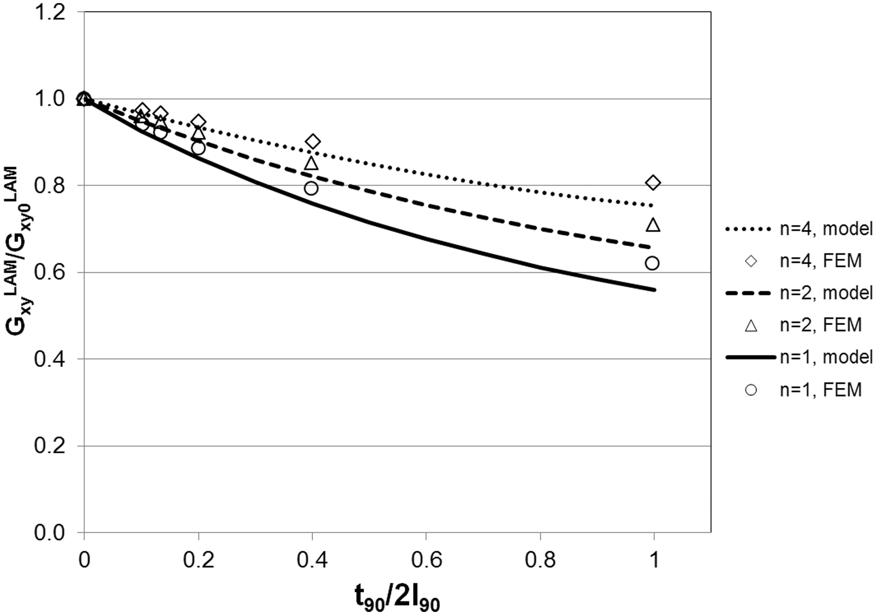
Accuracy of Soutis et al. model 12
As described in the introduction, the research group by Soutis et al.
12
suggested to improve the shear lag assumption-based stress distribution models by replacing the common assumption of linear out-of-plane shear stress distribution across the constraint layer thickness by another assumption which was based on analysis of FEM results. It was assumed that
Since the shape of the
Normalized complementary energy of
Normalized complementary energy of
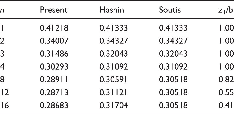
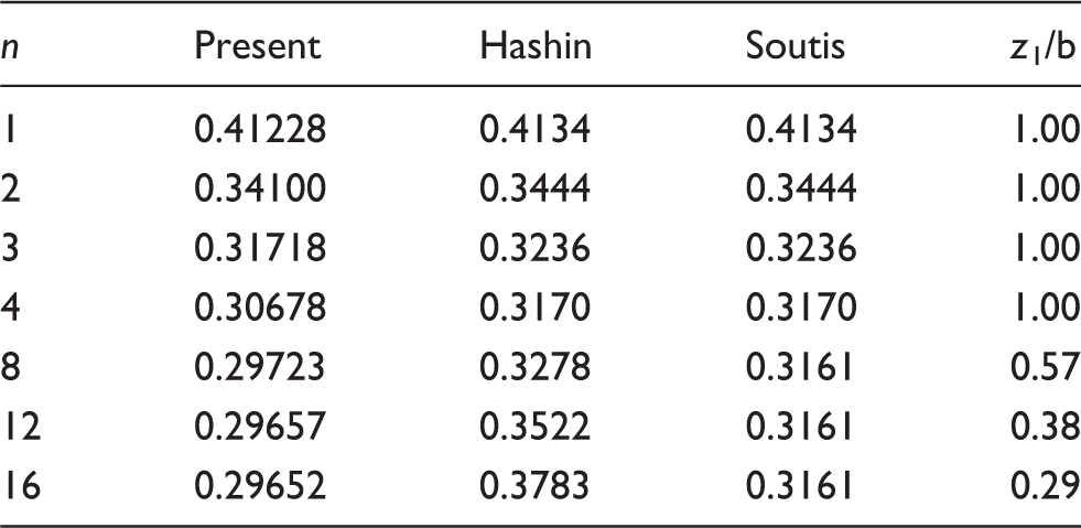
The complementary energy value according to the present model is the lowest for all configurations and crack densities which means that this model is the most accurate. Using Soutis model in cases when the 0-layer is thinner than the 90-layer
It has to be emphasized that the values of the complementary energy in Table 2 (for low crack density, (a) Shape of the out-of-plane distribution 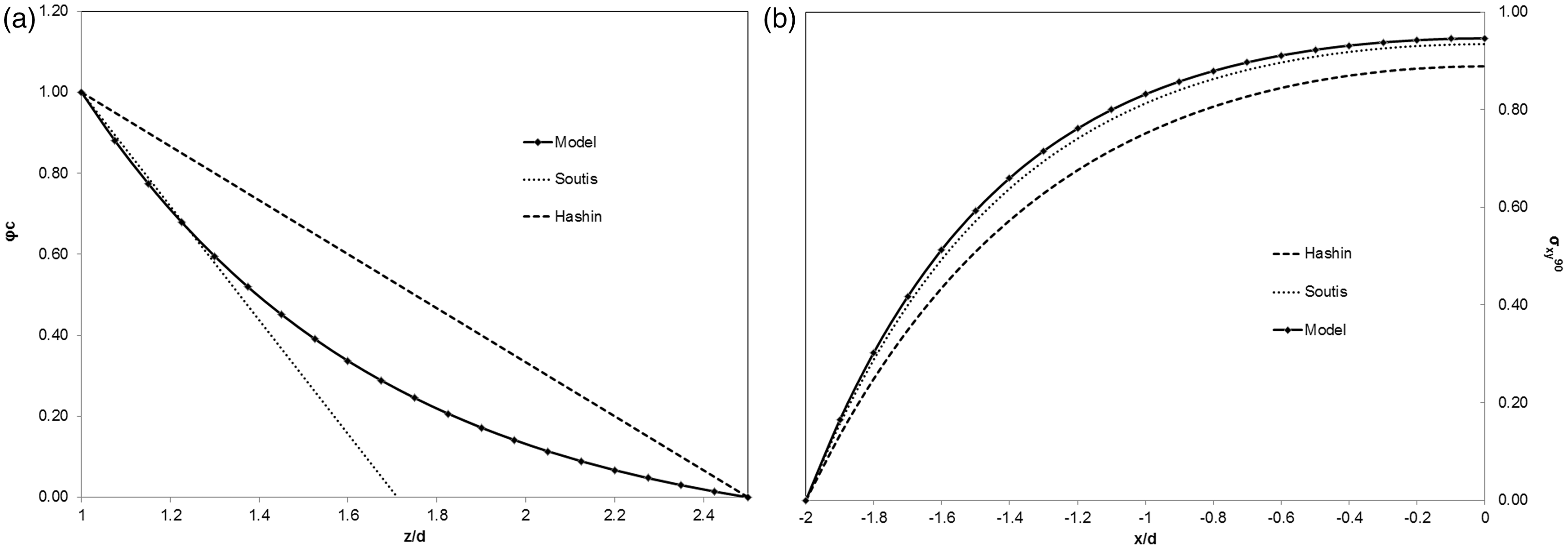
In the analysis, we assumed that cracks in surface layers are located symmetrically with respect to the middle-plane. Due to statistical failure properties distribution along the 90-layer, more probable is random location, especially for low crack density. For higher crack density, it may be more staggered (the crack in the bottom layer is located in the middle between cracks in the top layer). The variational stress model for the latter case was introduced by Nairn. 17 Since the variation of failure properties along the 90-layer transverse direction is much larger than the stress perturbation in the bottom layer of the laminate due to crack in the top layer, the assumption of staggered cracks and the assumed symmetry of the damage with respect to the mid-plane used in this paper may be two extreme cases.
Conclusions
The developed analytical model for the shear modulus of laminate with intralaminar cracks in 90-layer is based on minimization of the complementary energy. It is shown that this model is more general and accurate than the Hashin’s variational model, which was developed using an assumption that the out-of-plane shear stress has linear distribution across the thickness of the damaged layer and also across the thickness of the constraint layer. The refinement presented here consists of introducing an exponential shape function to characterize this distribution, with the shape parameters determined during minimization. Hashin’s model becomes a particular case of the present model.
As expected from an improved model based on minimization of complementary energy, the predicted laminate shear modulus is slightly higher than according to Hashin’s model. The difference is larger for laminates with relatively thin 90-layers. Laminates with damaged 90-layer in the central part as well as on the surface are analysed. The predicted shear modulus reduction is the same in both cases, when exponential shape function is used. The same conclusion follows from Hashin’s model and it is confirmed by FEM results.
Finally, it is shown that the shear lag model introduced by Soutis 12 with an unknown perturbation zone can be considered as a special case of the developed variational model and the size of the zone may be found. In this case, the shape function in the 0-layer is bilinear and the out-of-plane shear stress is active only in a part of the 0-layer. It is demonstrated that for relatively thick 0-layer, this model is more accurate than Hashin’s model but less accurate than the presented model. For laminates with relatively thin 0-layer, the results of the Hashin’s and Soutis models coincide.
A comparison with FEM results shows that the obtained shear modulus values are conservative and rather insensitive to the refinement of the stress description in the constraint layer. Therefore, improvement of the model requires introducing non-linear shape functions also in the damaged 90-layer.
Footnotes
Conflict of Interest
None declared.
Funding
This research received no specific grant from any funding agency in the public, commercial, or not-for-profit sectors.