
Abstract
A new micromechanical approach for predicting the compressive response of long fiber composites based on a periodic unit cell model with a centrally located imperfection is presented. A detailed comparative analysis between the proposed model and the existing models was performed at the macro and micro level. The results show that the periodic unit cell model with non-uniform fiber waviness is able to reproduce the mechanisms that govern the failure of fiber-reinforced polymers under compression and provide accurate characteristics of microbuckling.
Introduction
Failure of a carbon fiber-reinforced polymer (CFRP) under longitudinal compression is sudden and catastrophic. Experimental results indicate that it is triggered by microbuckling of fibers inside the inelastic matrix. As the compressive stress in the composite increases, the matrix is plasticized and individual fibers undergo significant bending. After the maximum of the compressive stress has been attained, geometric softening associated with the fiber bending outweighs the strain hardening of the matrix, and the composite starts to collapse. During the dynamic load drop, damage is localized within well-defined bands of kinked fibers. As the fibers snap, the kink bands are inclined typically at an angle 10°–30° to the transverse direction and have a width of 20–40 fiber diameter (see for example, Jelf and Fleck, 1 Moran et al., 2 Vogler and Kyriakides 3 and Gutkin et al. 4 ).
As compressive failure in fiber-reinforced composites is an unstable process, it is difficult to observe the precise sequence of events leading to the formation of kink bands. Experimental studies have been typically limited to measurements of the compressive strength. Therefore, computational micromechanics is used to understand and predict the post-critical response of fiber-reinforced composites subjected to longitudinal compression.
Various finite element models with initially wavy fibers and ductile matrix have been proposed for analyzing the plastic microbuckling over the past years. In these models the waviness is idealized as an infinite fiber/matrix series rather than as a finite region of higher misalignment. Generally, there are two types of micromechanical models aiming to reproduce the mechanisms that govern the compressive failure of fiber-reinforced polymer composites. In the first one, the longitudinal sides of model are free from constraints. This model will be called a finite width model (FWM) throughout this paper. The FWM is typically composed of several dozen alternate layers of the fibers and matrix explicitly modeled by finite elements. It has been used extensively by various research groups; see, for example, Kyriakides et al.,5 Hsu et al.,6 Vogler et al.,7 Byskov et al.,8 Pimenta et al.9 and Prabhakar and Waas.10 In the second one, periodic boundary conditions are prescribed on the longitudinal sides of model. This model will be called a infinite width model (IWM) throughout this paper. The IWM usually consists of one fiber embedded in matrix. The concept of the periodic unit cell model with uniform fiber waviness has been employed for analyzing the compressive failure process in unidirectional composites in papers by Guynn et al., 11 Morais, 12 Hsu et al., 13 Pansart et al. 14 and Gutkin et al. 15
A similar classification can be also applied to micromechanical models based on the Cosserat couple stress theory, see, for example, Fleck and Shu, 16 Fleck et al. 17 and Fleck and Liu. 18 The authors treated the composite as a homogeneous anisotropic solid and used the couple stress formulation to take the fiber bending resistance into account. In this approach, the effect of individual fibers is smeared out. This means that each element in finite element realization represents a domain of the composite which may contain many embedded fibers.
Both types of models have advantages and limitations. It is believed that the predictions of the FWM should tend to the results obtained from the IWM for a sufficiently large number of fibers. Unfortunately, a distinct difference in the deformation of the two models is observed. The free boundary conditions allow the deformation to localize along an antisymmetric band crossing the entire width of the model, provided that the geometry of fiber waviness is antisymmetric with respect to the longitudinal direction. On the contrary, the periodic boundary conditions force the deformation to be symmetric regardless of the geometry of fiber waviness. As a consequence of this, the FWM can ensure a realistic inclination of kink bands, contrary to the IWM in which the kink band angle is indirectly set to zero degree. Disregarding computational cost, there exists a maximum value of model width, beyond which the development of kink bands in the FWM is inhibited by the symmetries assumed at the top and the bottom of the model.5,7 On the other hand, there exists also a minimum value of model width below which the FWM does not facilitate the formation of the kink band. 10 This is because, the free boundary conditions produce severe stress concentrations at the free surfaces. This aspect was first reported by Waas et al. 19 who demonstrated that the presence of free boundaries can lower the buckling stress. The effect of the stress concentrations on the buckling stress becomes less pronounced as the number of fibers increases. To remove the effect of free edges completely, the periodic boundary conditions are enforced. Most of the existing models have concentrated on the prediction of failure from an idealized uniform distribution of fiber waviness. In reality, fiber-reinforced composites contain non-uniform waviness. While it is consensus that microbuckles start from the sites of stress concentrations at regions of fiber waviness, there is difficult to accept that they always initiate at free edges. Moreover, it was experimentally observed that microbuckles may initiate not only at the free surfaces but also in the interior at regions of higher misalignment, particularly when specimens are unnotched. 20 Thus, micromechanical models with non-uniform waviness have a valuable role to play. Unfortunately, to date, the effects of waviness distributions and free edges have been explored simultaneously, i.e. by using the FWM.5,7,8,16–18 As a consequence of this, the role of local stress concentrations due to the non-uniform distribution of fiber waviness has been weakened. Omitting the free edge effect is potentially useful from the point of understanding the compressive failure process.
The present work shows an alternative model for predicting the compressive response of long fiber composites in which free edges do not occur. To the author's knowledge, no attempt has been made yet to obtain a solution for the periodic unit cell model with non-uniform fiber waviness. The main novelty of this work lies in the fact that the mechanism of kink band formation at a finite region of fiber misalignment has been successfully modeled using the IWM. This new approach is motivated by two basic hypotheses. First, the formation of kink band is through a post-buckling process of localization. The localization of damage depends on material inhomogeneities, e.g. distribution of fiber waviness. Under this hypothesis, the direction of damage propagation is controlled by the local stress concentration developing at finite regions of higher misalignment. Second, it is possible to isolate a small volume element of a composite that is statistically representative of the material as a whole. Since damage initiates at the microscale, the onset and evolution of damage can be determined locally by analyzing the microscopic behavior of the unit cell.
Development of micromechanical models
Geometry of micromechanical models
Real microstructures of continuous fiber-reinforced composites are very complex. Fiber waviness is always present, even when great care is taken to align the fibers during processing. Moreover, the amount of fiber misalignment varies from fiber to fiber. Although some fiber misalignment exists throughout the material, the waviness is more severe in bands of characteristic widths which are periodically distributed in the transverse direction. In this paper, attention will be limited to two waviness distributions of the type used by Kyriakides et al. 5 In both cases, the geometry of the model represents a two-dimensional (2D) layered material. It is well documented in the literature6,7 that the compressive responses of 2D models exhibit the same features as those from 3D models, and the 2D models are reliable tools for predicting the compressive strength and the post-critical behavior of a unidirectional fiber-reinforced composite. For the presentation of the problem, the material coordinate system is introduced so that the x1 axis is aligned with the fiber direction and the x2 axis is perpendicular to the fiber direction.
In the first case (Figure 1(a)), an initial fiber imperfection is uniformly distributed across the width of the model. This imperfection is expressed as a sinusoidal waviness of fibers along the x1 direction with amplitude a and wavelength 2λ
Geometry of micromechanical models with (a) uniform sinusoidal imperfection; (b) non-uniform sinusoidal imperfection.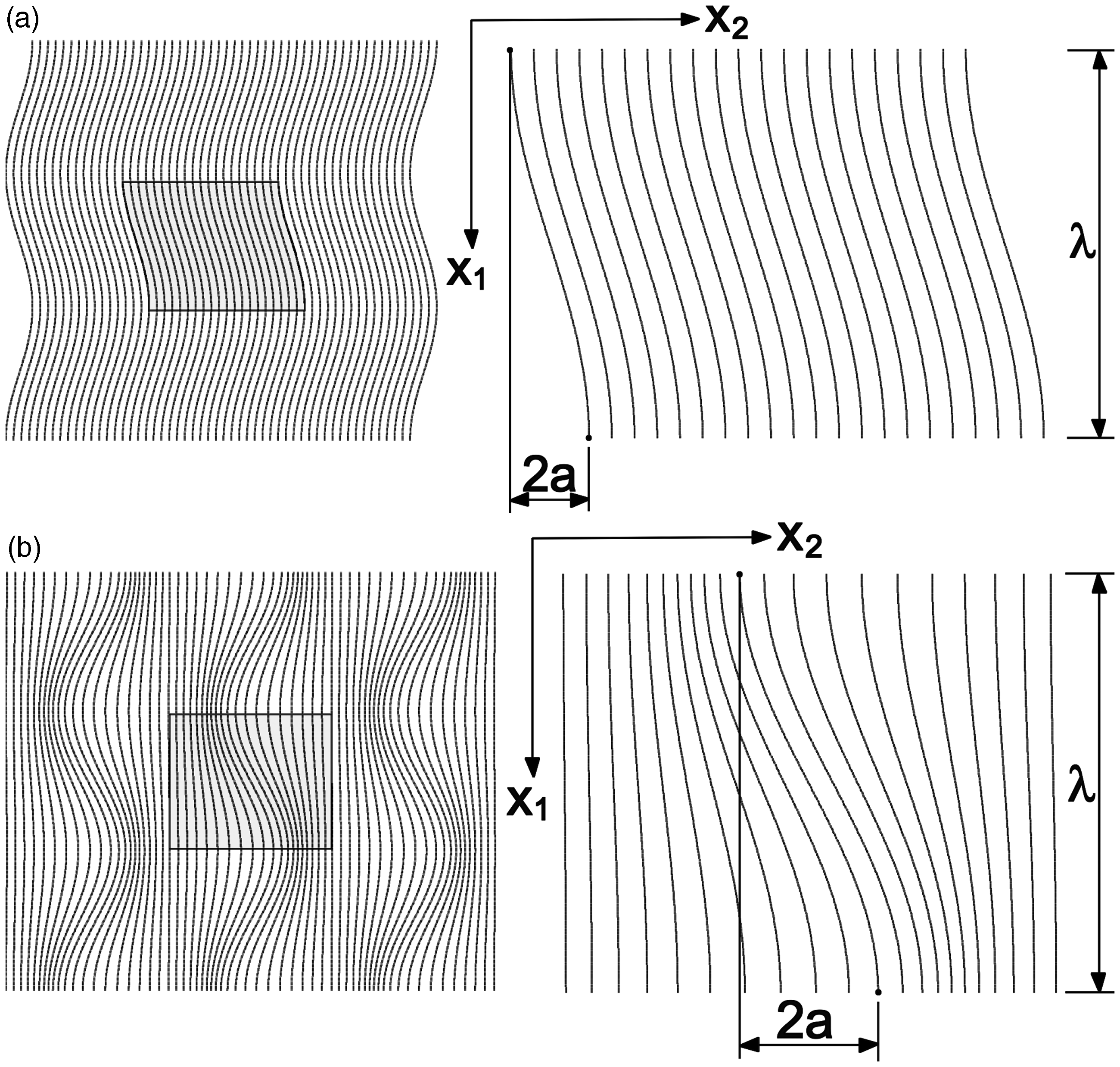
If the sinusoidal imperfection has long wavelength and relatively small amplitude, the fiber misalignment angle can be approximated by

In the literature,21,22 the values of the initial fiber misalignment Θ are usually 2°–3°. Unit cell models with the uniformly distributed imperfection characterized by Θ = 1.71°, 2.40° and 3.42° were analyzed.
In the second case (Figure 1(b)), an initial sinusoidal imperfection has a non-uniform distribution across the width of the model. That is, the amplitude of the imperfection has its maximum at the center of the model and decays exponentially with distance from the mid-width, as follows

In both model geometries, the width of matrix regions was chosen so as to accommodate the fiber diameter df = 7 µm, and respect the fiber volume content Vf = 60%. The length of models corresponds to the half wavelength, λ = 75df. Models of finite width defined by the number of fibers nf = 60 were used in this study.
Finite element formulation
Finite element models are constructed by using ANSYS finite element code. 23 2D finite element meshes made of plane strain, biquadratic elements with eight nodes (Plane183) are generated for the appropriate geometries of micromechanical models. The fiber and matrix layers each have 1575 and 2100 elements, respectively. The corresponding mesh density is found to be adequate for sufficient solution accuracy. A displacement controlled uniform compressive loading is applied at the top side of the unit cell. The bottom side of the unit cell is fixed in the vertical direction. One node was also fixed in the direction perpendicular to the compressive load to prevent rigid body motion. In order to assess the effect of free edges on the calculated compressive response of the composite, the same finite element analysis was performed by applying two different boundary conditions prescribed on the right and left sides of the unit cell.
The first one assumes that models have a finite width and there are no constraints at the lateral edges. The results of these models will serve as a base for further comparison. As it was mentioned above, the free edge boundary conditions cause significant non-uniformity in stress distribution. This is because the fibers located along a free edge bend more easily compared to the internal fibers due to the lower level of fiber support. The magnitude and extent of the axial stress concentrations due to the free edges have been considered by Kyriakides et al. 5 and are not repeated here.
Alternatively, the second type of boundary conditions assumes that models have infinite width. This assumption implies that the periodicity conditions on the longitudinal sides of the unit cell are defined to represent a periodic microstructure consisting of an infinitely large array of repeated unit cells. The displacements of nodes on the right side of the unit cell are related to the displacements of their counterparts on the left side as follows (similar as in Pansart et al.
14
)
Constituent properties

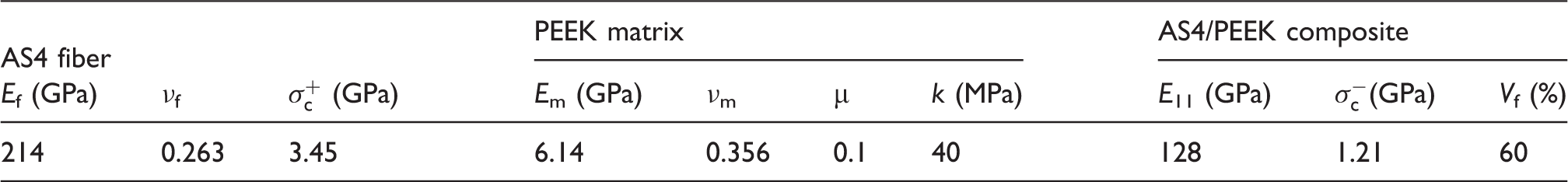
Mechanical properties of the AS4/PEEK composite and its constituents. 5
Calibration of the Drucker–Prager plasticity model
Micromechanical models require in-situ properties of constituents that are different from bulk properties. It was experimentally demonstrated by Gregory and Spearing
29
that the matrix in the AS4/PEEK composite is considerably stiffer and stronger than the neat polymer. In this paper, the in-situ axial stress–strain curve of the matrix is back-calculated from the shear stress–strain curve of the AS4/PEEK composite by using numerical homogenization. To simulate in-plane shear loading, a 2D unit cell with perfectly straight fibers and periodic boundary conditions prescribed on all edges was used. A hardening curve for the PEEK matrix was determined iteratively so that the predicted shear response of the composite matches the measured shear response. Comparisons of the in-situ axial response of the matrix and the predicted shear response of the composite with corresponding test data
5
are shown in Figure 2(a) and (b). It can be seen from Figure 2(b) that the axial stress–strain curve of the matrix shown in Figure 2(a) produces an accurate solution for the AS4/PEEK composite under in-plane shear loading. Subsequently, this calibrated model of the matrix was used to predict the compressive response of the composite.
Identification of the plasticity model. (a) comparison of the in-situ axial response of PEEK matrix with test data [5] (b) adjusting experimental shear response of the AS4/PEEK composite [5] with model response.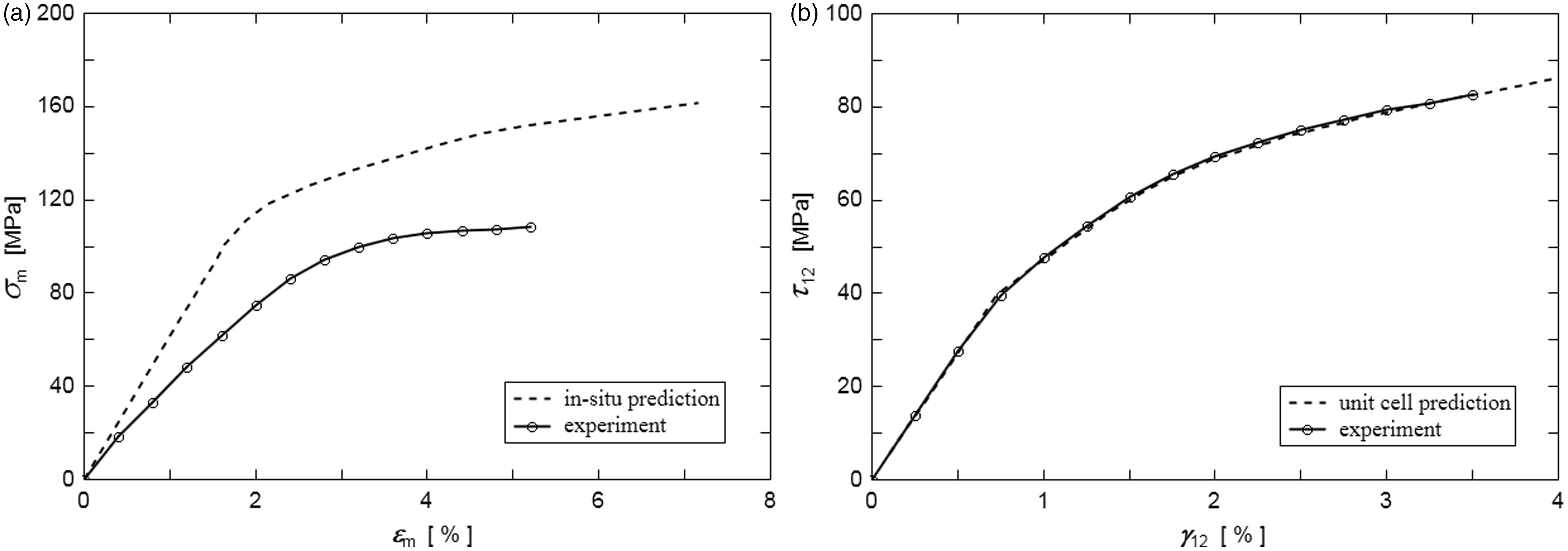
Solution strategy
In order to handle the potential snap-through associated with the post-buckling response effectively, the arc-length method 30 is adopted. A minimum arc-length radius was defined by using the following parameters. The minimum multiplier of reference arc-length radius was rmin = 10−8. The number of substeps was n = 2500. A residual forces tolerance of tolF = 0.001 was selected to control the convergence of the iterative procedure.
The compressive responses of the unit cells are discussed in terms of macroscopic stress and strain. According to the homogenization theory, the macroscopic compressive stress σ11 is equal to the average normal traction at the bottom edge of the model (obtained as the sum of reactions divided by the actual cross-section). The corresponding average strain ɛ11 was computed from logarithmic formula, namely ɛ = ln(1 + δ/λ), where δ is the displacement of nodes at the top edge of the model.
Results
Depending on the distribution of fiber imperfection and the type of boundary conditions, four different microbuckling models were considered, namely: the IWM with uniform waviness, the IWM with non-uniform waviness, the FWM with uniform waviness and the FWM with non-uniform waviness. A detailed comparative analysis between the micromechanical models was performed at the macro and micro level.
Analysis of global behavior
The macroscopic stress–strain curves calculated for two different distributions of fiber imperfections are shown in Figure 3(a) and (b). Predictions obtained from the model of infinite width (IWM) are plotted in these figures as dashed lines and, in turn, predictions from the model of finite width (FWM) as solid lines.
Prediction of the compressive stress–strain curves. Results are obtained from models with different boundary conditions at lateral edges for two kinds of imperfection distribution. (a) responses for uniformly distributed imperfection characterized by θ; (b) responses for centrally located imperfection with decaying amplitude characterized by α.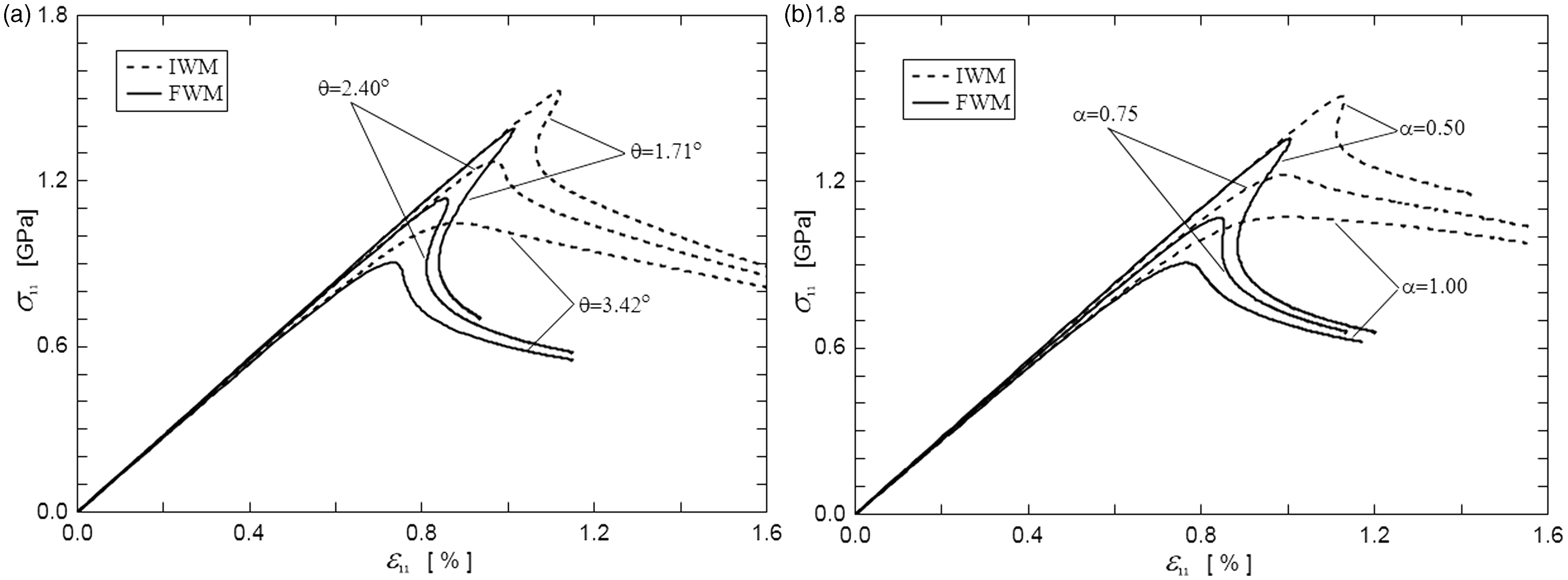
The curves shown in Figure 3(a) relate to models which have uniform fiber imperfections. The results presented in this figure illustrate the effect of the fiber misalignment angle Θ, on the overall compressive response of the AS4/PEEK composite for the models of infinite and finite width. The main features of the compression curves for the FWMs are qualitatively very similar to the ones found by Kyriakides et al. 5 by using the von Mises yield function. The stiffness of the composite is progressively reduced due to the geometric softening resulted from bending of the fibers combined with decreasing the stiffness of the matrix. The results confirmed the well-known sensitivity of compressive strength to the misalignment angle. An increase of the fiber misalignment angle Θ reduces the compressive strength of the composite as well as the snap-through instability beyond the limit load for both types of boundary conditions. However, it is interesting to note that the solutions for the FWM are quantitatively different from these found for the IWM. Due to some stress concentrations developing on the free edges, the limit stress and limit strain are lower and the post-buckling response is more sudden and sharper.
The curves for the case of centrally located imperfections with decaying amplitude are reported in Figure 3(b). The results presented in this figure illustrate the effect of the ratio of the number of imperfect fibers to that of the total number of fibers α, on the overall compressive response of the composite for the models of infinite and finite width. An increase of the ratio α reduces the compressive strength of the composite as well as the snap-through instability beyond the limit load in the same way as the angle Θ. Similarly, it can be also observed that the IWM has significantly higher limit stress and limit strain than the FWM with the same parameter α as well as the post-buckling response from the IWM is less sudden and not as sharp as that from the FWM.
By comparing the results from two different distributions of fiber imperfections (Figure 3(a) and (b)), it can be concluded that the compressive response predicted by the model with a decaying amplitude of imperfection has the same general characteristics as the corresponding response predicted by the model with a uniform imperfection. However, it should be noted that regardless of the kind of fiber imperfection distribution, the snap-through instability is more severe for models that have finite width and no constraints are imposed at the lateral edges.
In order to validate the calculated compressive strengths, the limit stresses obtained through the presented models were compared to experimental data reported by Kyriakides et al.
5
The results of this comparison are summarized in Figure 4(a) and (b). From these figures, it is seen that the compressive strengths predicted by the models with the imperfection parameters Θ = 2.40° and α = 0.75 are in very good agreement with experimental data. For purposes of the local analysis, the models with the above parameters will be considered.
Comparison of the calculated critical stress with experimental data [5]. (a) values for uniformly distributed imperfection characterized by θ; (b) values for centrally located imperfection with decaying amplitude characterized by α.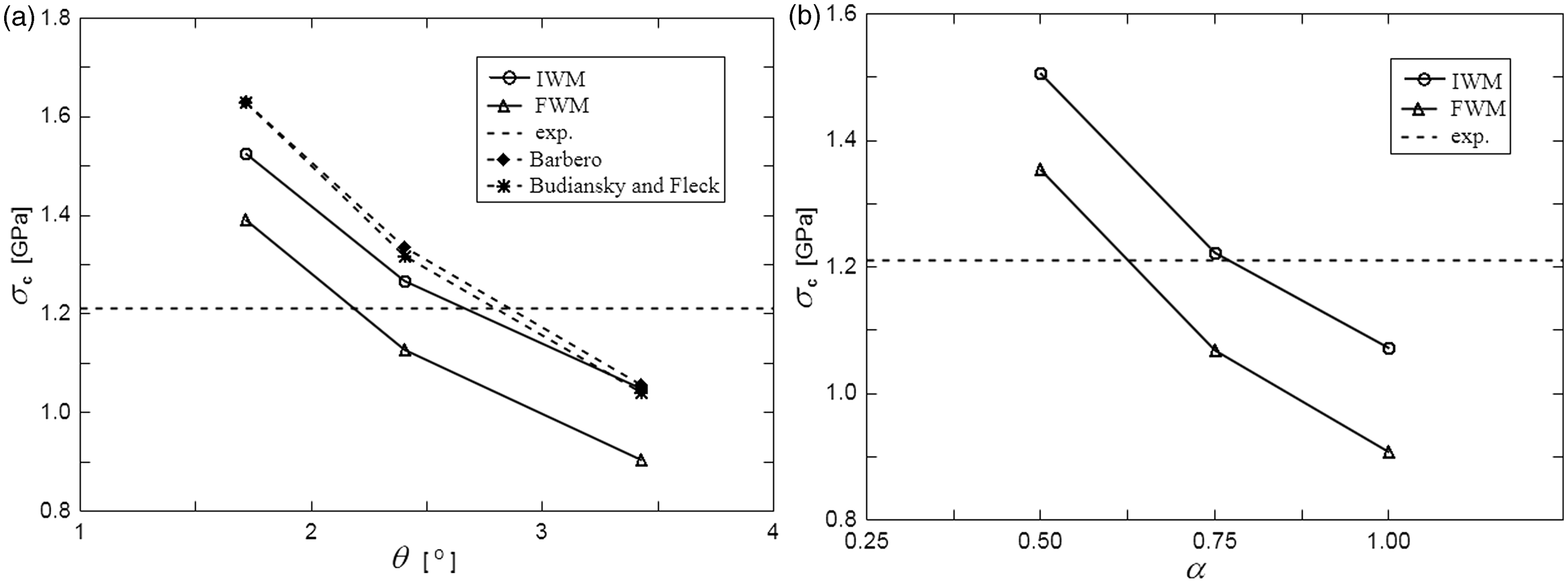
To see whether the numerical models produce results consistent with those obtained with the analytical models, two analytical formulations proposed by Budiansky and Fleck
31
and Barbero
32
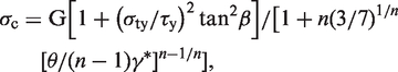
are considered. The first model is based on the physics of kink band formation and the second model on the stability analysis. Both models take into account the matrix physical non-linearity and the presence of initial fiber misalignment. The Budiansky and Fleck theory suggests that the longitudinal compressive strength σc can be derived as

Analysis of local behavior
Failure mechanisms under uniaxial compressive loading can be ascertained from contours of the effective plastic strain in the matrix and an evolution of the axial stress in the fibers.
The contour plots of the effective plastic strain are shown in Figures 5 to 8 in three stages of deformation that represent different responses of material, namely the beginning of plastic flow, the limit load and the post-buckling behavior. The development of plastic deformation in the matrix was demonstrated in four cases depending on whether periodicity conditions are prescribed and whether there exists an inhomogeneity of fiber imperfection. An adequate model should properly reproduce the kink band formation and propagation. That is, the yield bands in the model should rotate and broaden in a manner similar to kink bands observed experimentally.1–3,5 Experimental observations show that, as the load begins to drop, the fibers in the PEEK matrix composite rotate rapidly until the kink band angle reaches the value of 15°. In the post-buckling stage, the band inclination remains constant but the band width grows. The inclinations of the yield bands calculated in the post-buckling stage from the models are listed in Table 2. In three of four models, the predicted angle is in a good agreement with the measured value. Only for the IWM with uniform waviness, the kink band angle is constant and equals zero. It is interesting to note that the other models deform with the non-zero kink band angle for various boundary conditions and various distributions of fiber imperfection. The common feature of the other models is the presence of stress concentrators. Thus, this finding suggests that the kink band angle is controlled by stress concentrations developing either at regions of maximum fiber misalignment or at free edges.
Contour plots of the effective plastic strain in the matrix predicted from infinite width model with uniformly distributed imperfection at three stages of deformation corresponding to (a) the beginning of plastic flow (ɛ11 = 0.57%); (b) the limit load (ɛ11 = 0.98%); (c) the post buckling (ɛ11 = 1.50%). Inclinations of the yield bands calculated in the post-buckling stage. IWM: infinite width model; FWM: finite width model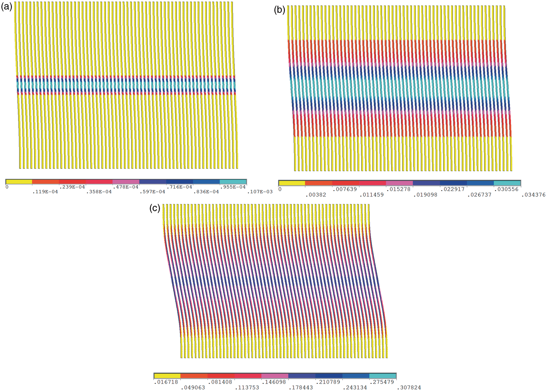
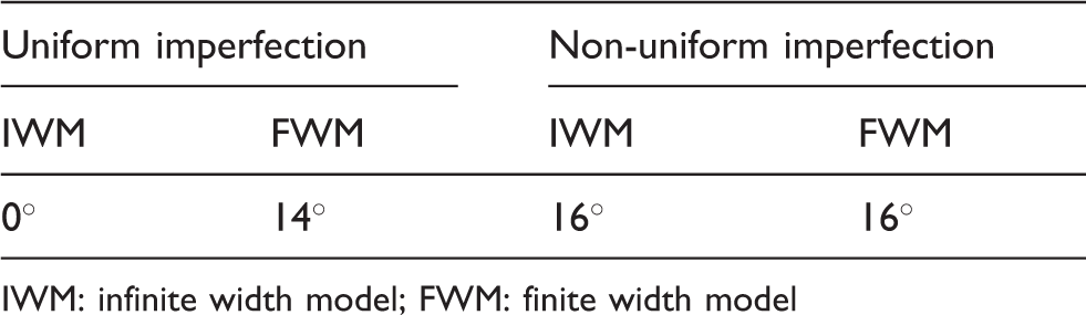
The contour plots of the effective plastic strain for the case of the uniform sinusoidal imperfection characterized by Θ = 2.40° are shown for models of infinite and finite width in Figures 5 and 6, respectively. Note, that the plastic deformation starts to localize in a narrow band crossing the models at the mid-length before the limit load is reached (Figures 5(a) and 6(a)). By comparing the solutions obtained for both types of boundary conditions, it can be concluded that the development of plastic deformation in the matrix for the case of the FWM is quite different from the case of the IWM. As can be seen in Figure 6, a band of the most intense plastic deformation for the FWM becomes increasingly more inclined as the bending curvature increases. Thus, this model allows to simulate the kink band development compared to the IWM in which the yield band inclination constantly equals zero. As can be seen in Figure 5, the lack of the stress concentrators forces the yield band to spread into the unkinked material by band width broadening. From the above analysis, it is quite evident that a stress concentration developing on the free edge is a main factor controlling the localization of plastic deformation in the matrix for the case of the uniform sinusoidal imperfection.
Contour plots of the effective plastic strain in the matrix predicted from finite width model with uniformly distributed imperfection at three stages of deformation corresponding to (a) the beginning of plastic flow (ɛ11 = 0.54%); (b) the limit load (ɛ11 = 0.85%); (c) the post buckling (ɛ11 = 1.15%).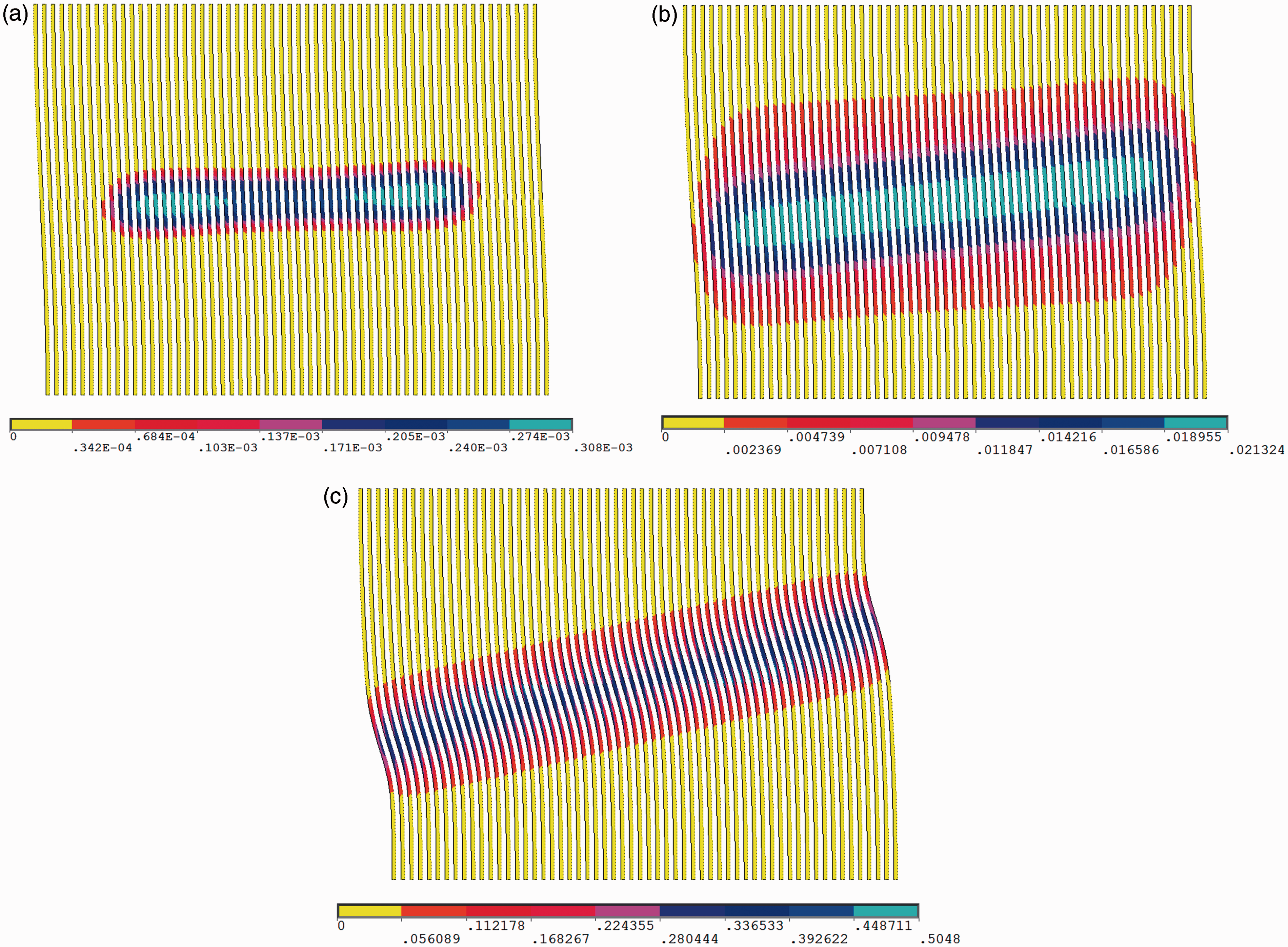
In order to investigate whether the inclination of yield bands can be brought about by other sources of stress concentration, the effective plastic strain in the matrix was calculated for models with the non-uniform distribution of sinusoidal imperfection characterized by α = 0.75. The contour plots of the effective plastic strain shown in Figures 7 and 8 relate to the models which have infinite and finite width, respectively. Note that earlier yielding of the matrix takes place in the center of the models (Figures 7(a) and 8(a)). This is because the fibers in the center bend more easily compared to the fibers located close to the lateral edges due to the larger fiber misalignment. Thus, this region is the site where a stress concentration develops and microbuckle initiates. After the initiation stage, bands of the most intense plastic deformation run across the width of the models and rotate. The results given in Figures 7(c) and 8(c) indicate that the inclined bands of the plastic deformation associated with significant bending of the fibers have formed in both micromechanical models. Thus, it is also possible to obtain an accurate characteristic of the growing kink bands for the case of IWM provided that an inhomogeneity of fiber imperfection exists. In the case of periodic model (Figure 7(c)), the propagation of kinking is observed in two inclined bands that are separated from each other and clearly defined. Whereas, the corresponding bands obtained from the model of finite width (Figure 8(c)) join into one band that resembles that shown in Figure 6(c) from the uniform distribution. At first glance, the inclined bands in Figure 7(c) are significantly different from these in Figures 6(c) and 8(c), but note that the two inclined bands in Figure 7(c) match each other perfectly because the model is mirrored infinitely. Due to the periodicity in the transverse direction, the solution shown in Figure 7(c) can be regarded as a single band that spreads out from one maximum fiber misalignment to another through a region of initially straight fibers. Thus, the new approach also produces results which are consistent with the experimental observations. From the above analysis, it is quite evident that a stress concentration developing at regions of higher misalignment plays the same role as a stress concentration at free edges.
Contour plots of the effective plastic strain in the matrix predicted from infinite width model with centrally located imperfection at three stages of deformation corresponding to (a) the beginning of plastic flow (ɛ11 = 0.43%); (b) the limit load (ɛ11 = 0.99%); (c) the post buckling (ɛ11 = 1.56%). Contour plots of the effective plastic strain in the matrix predicted from finite width model with centrally located imperfection at three stages of deformation corresponding to (a) the beginning of plastic flow (ɛ11 = 0.41%); (b) the limit load (ɛ11 = 0.85%); (c) the post buckling (ɛ11 = 1.1%).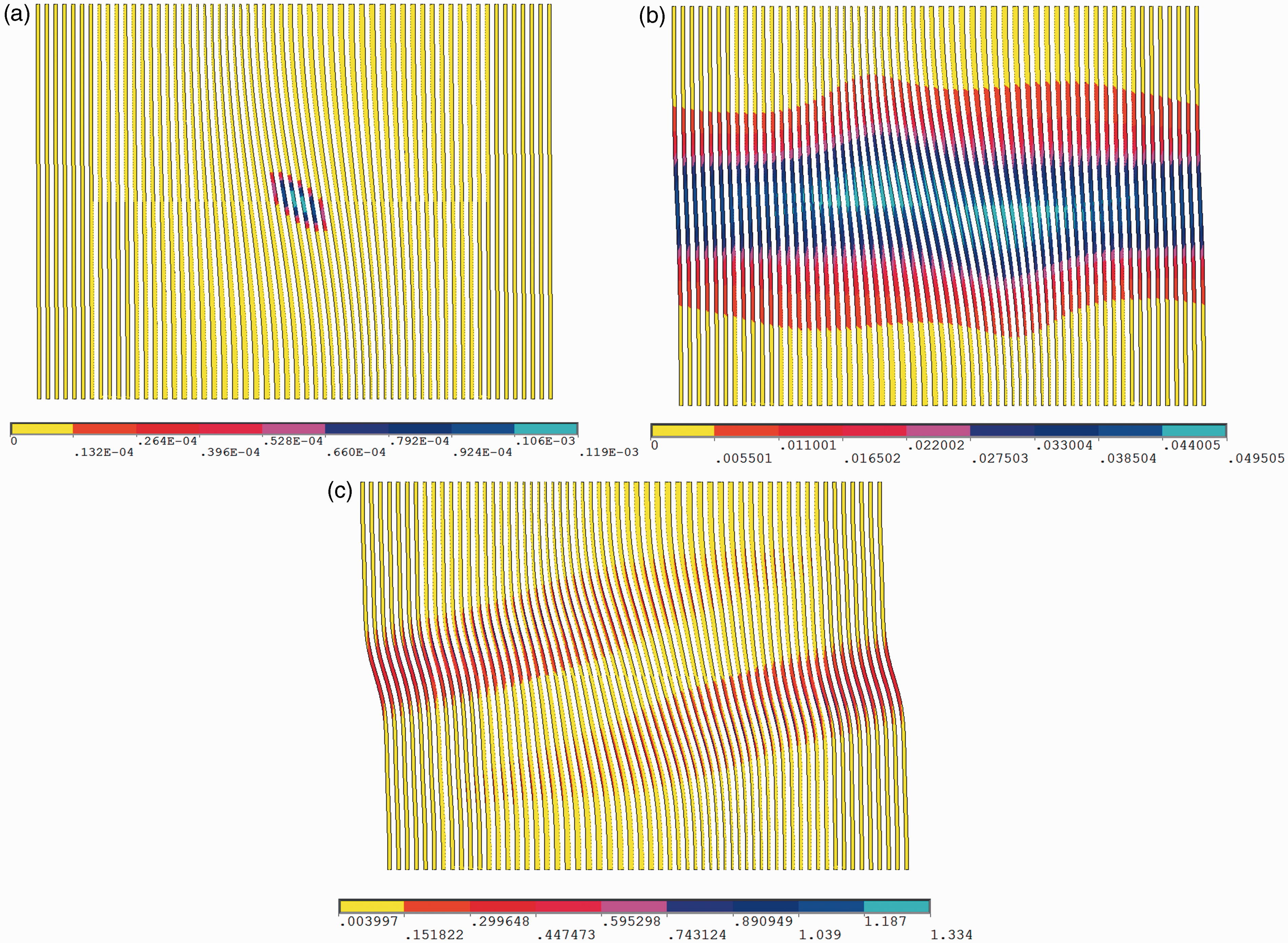
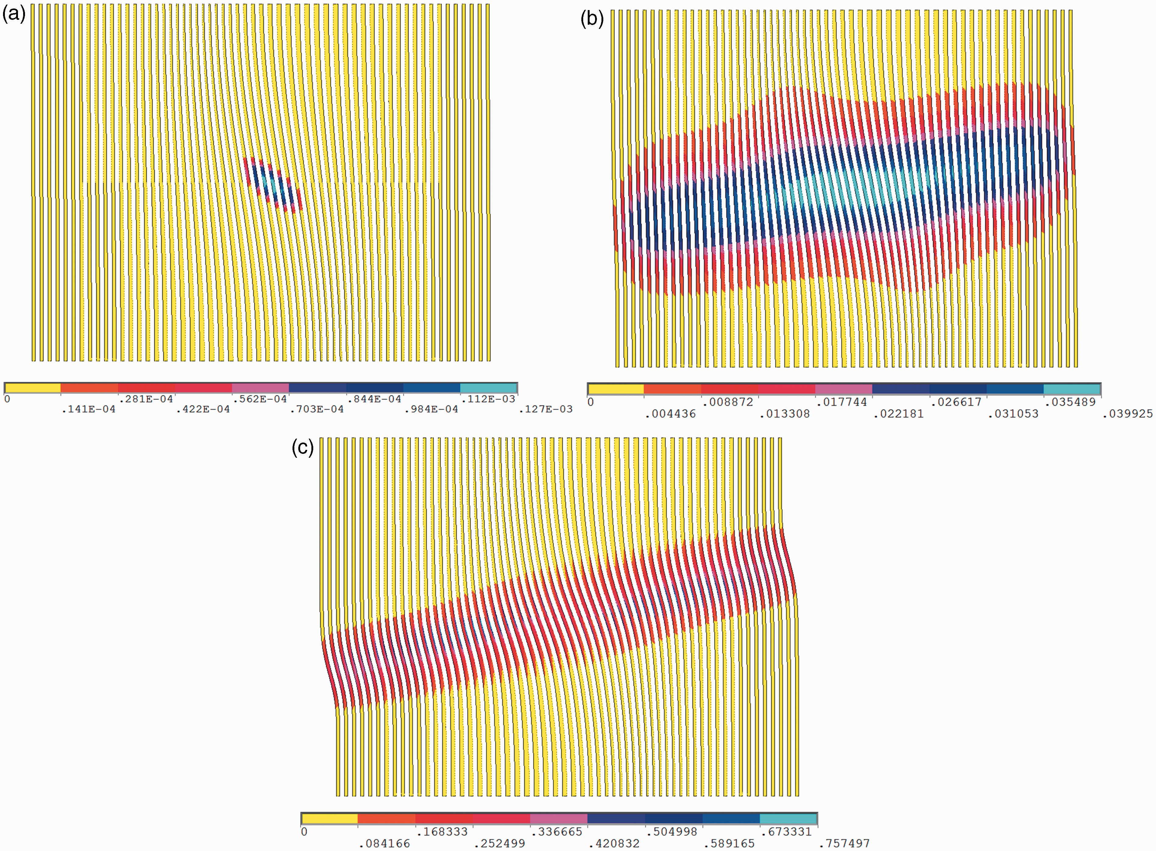
However, a significant difference can be observed in the sequence of events that resulted in the formation of kink band. From the predictions of kink band presented in Figures 6 to 8, it is apparent that this sequence depends on boundary conditions at the lateral edges. Figures 6(b) and 8(b) show the contour plots of the effective plastic strain predicted from the models with free edge boundary conditions for the limit load. They are obtained for two different fiber imperfection distributions. The solution for the limit load predicted from the model with periodic boundary conditions for non-uniform imperfection is shown in Figure 7(b). The yield band corresponding to the limit load retains an inclination of zero degree in the case of the IWM. Contrary to what was observed in the IWM, the plastic deformations for the FWMs were found to localize in inclined bands before the instability takes place. Moreover, the non-zero inclination of the yield band occurs in the FWM even in straight fibers regions (Figure 8(b)). Thus, only the sequence of events presented in Figure 7 follows the hypothesis that the formation of kink band is through a post-buckling process of localization.
The rotation of fibers and evolution of kink bands in real composites take place until the fibers break due to a combination of bending and compression. When the kink bands are fully developed their edges are defined by traces of the fiber failure planes. The in-situ micrograph of kink band formation
4
reveals that cracks in fibers are open which is attributed to the presence of tensile stress. Figure 9(a) and (b) shows how the maximum axial stress in a central fiber Comparison of the maximum stress in central fiber as a function of compressive strain. Results are obtained from models with different boundary conditions at lateral edges for two kinds of imperfection distribution. (a) responses for uniformly distributed imperfection characterized by θ; (b) responses for centrally located imperfection with decaying amplitude characterized by α.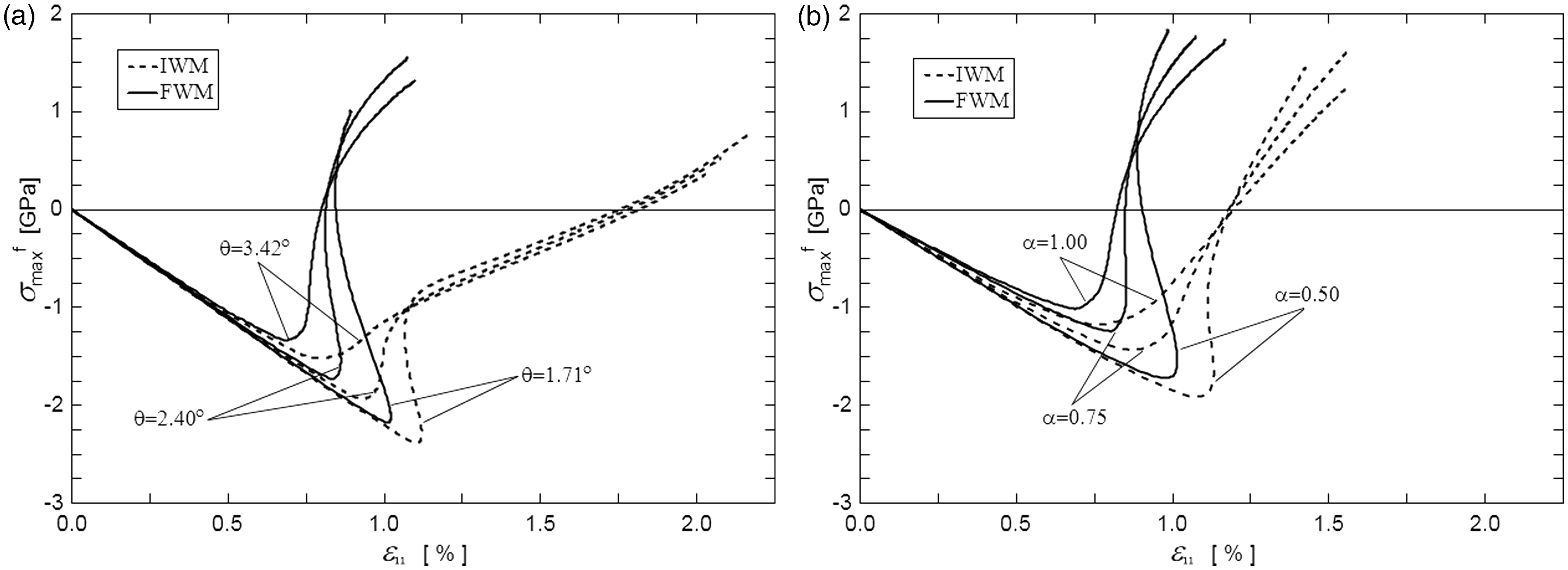
It is interesting to observe that the results of the FWMs obtained for two different distributions of fiber imperfection (solid lines in Figure 9(a) and (b)) are very similar. For the case of models of finite width, the axial stress in the central fiber becomes tensile at approximately the same load level and the transition is equally sudden for both kinds of imperfection distribution. Thus, the post buckling response of fibers predicted by the FWM is insensitive to the kind of imperfection distribution. The explanation of this is that in the case of FWM regardless of the kind of imperfection used, microbuckling is governed by the same stress concentrations developing at the free edges. This finding suggests that stress concentrations developing at the free edges are dominant.
On the contrary, by comparing the results of the IWMs obtained for two different distributions of fiber imperfection (dashed lines in Figure 9(a) and (b)), it can be concluded that the transition from compression to tension is significantly slower and more gradual in models that have uniform imperfections. This difference is due to larger value of the amplitude of imperfection at the centre of the models with non-uniform imperfections (Θmax = 9.60°) than these one with uniform imperfections (Θ = 1.71°, 2.40° and 3.42°). In this case, as expected, the post buckling response of fibers is sensitive to the kind of imperfection distribution.
Concluding remarks
A numerical study was performed to demonstrate that a periodic unit cell model with a centrally located imperfection is able to reproduce mechanisms that govern failure of fiber-reinforced polymers under compression. In particular, the proposed model correctly simulates the formation of inclined bands of bent fibers as a result of the interaction of local fiber instabilities and material non-linearities. The most important feature of this model is that a stress concentration can develop only in the interior due to increasing amplitude of the fiber imperfection in contrast to existing models in which stress concentrations at free edges dominate. Comparison of such a model with those reported in the literature on compressive failure showed that it calculates the limit load equally well as the periodic unit cell model with uniform waviness and predicts the post-critical events equally well as the models with free edge boundary conditions.
The study provides also new insight into the significance of non-uniform waviness in modeling the kink band initiation and propagation. In particular, it was shown that some stress concentrations developing at finite regions of higher misalignment play the same role as stress concentrations at free edges. This finding has an important implication for further research on random fiber waviness by means of models in which fibers are explicitly modeled by finite elements. To date, the effect of random fiber waviness was modeled only by using finite element formulations based on the couple stress theory. 33 The author believes that the progressive increase of computational power makes it nowadays possible to simulate the compressive response of long fiber composites with random fiber waviness on the basis of the proposed model.
Footnotes
Funding
This work is supported by National Science Centre of Poland under contract DEC-2011/03/D/ST8/04817.
Conflict of interest
None declared.