
Abstract
Woven fabrics used in composite materials are designed to fulfill specific manufacturing or structural requirements. Knowledge of the influence of the weave structure on the mechanical properties of the composite is essential to properly optimize the design of structural components. The focus of this work is to investigate the influence of the type of weave used for fabric reinforcement in polymers particularly on the in-plane shear mechanical performance. The selected materials are carbon fibers and epoxy resin. The laminates are manufactured by vacuum infusion. Three woven structures are selected for manufacturing the composite laminates: (a) a plain weave with unidirectional orientation in the warp direction, (b) a plain weave with balanced properties in the warp and weft directions and (c) a 2/2 twill weave with balanced properties in the warp and weft directions. The laminates are tested according to the ASTM D 4255 standard by a two-rail shear test under quasi-static monotonic and cyclic loading conditions. The resulting stress–strain curves are used to study the initial in-plane shear modulus and its evolution (which directly correlates with material damage) and the hardening produced by plastic strain. The results show that for vacuum infusion manufacturing, the weave structure has an influence on the resulting fiber and void volume fractions and, consequently, on the mechanical performance. However, for similar fiber volumes, the weave structure is found to have little effect on the experimental results.
Introduction
A wide range of composite materials used for structural applications are made from polymers reinforced by long fibers. These fibers can be arranged in reinforcement fabrics with different structures to fit a particular set of requirements (design, manufacturing or performance). The fabric structure influences the mechanical properties of the composites, as demonstrated by Adumitroaie and Barbero.1,2 In addition, the fabric structure has an influence on the damage suffered by the material3,4 when it is subjected to stress states both within the elastic limit and to total failure.
As established by Böhm et al., 5 the damage a composite suffers depends on the nature of the type of reinforcement. According to Böhm et al., unidirectional composite damage mechanisms can be separated into three categories: fiber failure, inter-fiber failure and delamination. Textile-reinforced composites may simultaneously undergo different damage mechanisms, such as microcracking, interface failure, void initiation, void growth or whitening. In addition, the particular stress states may have a greater influence on the material damage depending on the fabric structure. These factors have motivated the development of differentiated phenomenological constitutive laws for unidirectional and textile-reinforced composites.5,6
In-plane shear states induce nonlinear material behaviors, including large amounts of damage to the material, hardening and permanent deformation, independent of the nature of the reinforcement. A quick examination of the experimental yield and failure stress envelopes reveals the dominant influence of shear states on the damage area. 7 Greve and Pickett 8 explain the damage in a lamina (for noncrimping fabric composites) subjected to pure in-plane shearing as the initiation and evolution of matrix micro-shear cracking until a saturation level is reached, which produces a macro-shear crack. This phenomenon is represented by an exponential shear damage function that asymptotically reaches the shear damage saturation level. The same behavior has been shown by Fouinneteau and Pickett 9 for woven and braided fabric composites.
In this work, we present an experimental campaign to evaluate the influence of woven fabrics on the mechanical behavior of composite materials under in-plane shearing. Four carbon fiber fabric configurations are chosen for epoxy resin reinforcement. The composite laminates are manufactured by liquid transfer molding techniques, and the material is tested under monotonic and cyclic loading according to the ASTM D 4255 standard. The analysis is based on the influence of the reinforcement on the shear stress–shear strain curves, focusing on the initial shear modulus and its evolution in terms of the plastic strain and the material strain hardening.
Experimental campaign
Material manufacturing
Description of woven fabrics used as reinforcement.
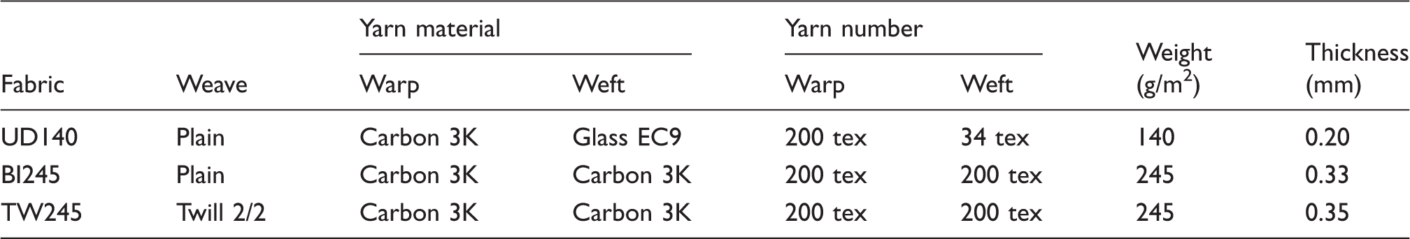
The matrix used for these experiments is an HT2 thermoset resin from Poxy System provided by R&G Composite Technology, Germany. The in-solution resin viscosity with the hardener is 201 mPa s (material data sheet; determined following the ISO 9371 standard), and the curing time is 24 h at room temperature. The cured resin density, measured using a scale with a precision of 0.0001 g, is ρm = 1.147 ± 0.002 g/cm3 (according to the ASTM D 792 standard). Figure 1 shows the stress–strain resin behavior under monotonic, quasi-static, room temperature in-plane shearing (ASTM D 4255). The material demonstrated an elastic-perfectly plastic behavior. Shear modulus for the cured resin is 916 ± 18 MPa obtained by a two-rail shear test according to ASTM D 4255 standard.
In-plane shear behavior of the cured resin sheet.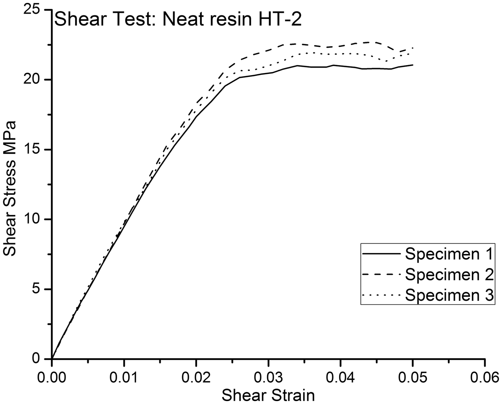
The laminates (400 mm × 250 mm) are manufactured by vacuum infusion and cured at room temperature for 72 h.
Laminate material properties.
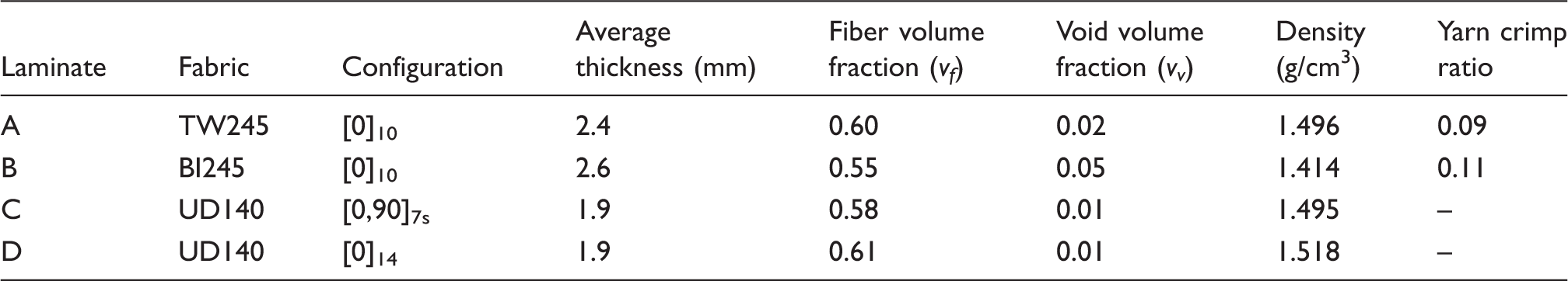
Laminates A, C and D have similar densities and fiber volume fractions (a relative difference of less than 2% for the density and 5% for the fiber volume fraction). Laminate B has a lower fiber volume fraction, a higher void content and a lower pre-form compaction (determined by comparing the laminate thicknesses in Table 2 and the fabric thicknesses in Table 1). The weave structure, which depends on the manufacturing procedure, has an influence on these parameters.12–15
Mechanical testing
The two-rail shear test (based on the ASTM D 4255 standard) was selected to evaluate the mechanical performance of the different laminate configurations under in-plane shearing at room temperature for monotonic and cyclic (approximately eight loading/unloading cycles) quasi-static conditions.
The two-rail, in-plane shear test device is mounted to an Instron 8801 testing machine. The shear strain is computed from data obtained using a strain gage (length: 5 mm, width: 3.5 mm, gage length: 5 mm, gage factor: 2.1, gage resistance: 120 Ω) placed along the principal strain direction, i.e., at 45° from the direction of the applied load (see Figure 2). The tests are performed at a loading and unloading speed of 0.3 mm/min and all tests are controlled by the displacement of the machine’s cross-head. The tests are stopped at a shear strain of 0.05 because the standard establishes this value for computing the in-plane shear strength.
Laminate specimen in the two-rail in-plane shear test device.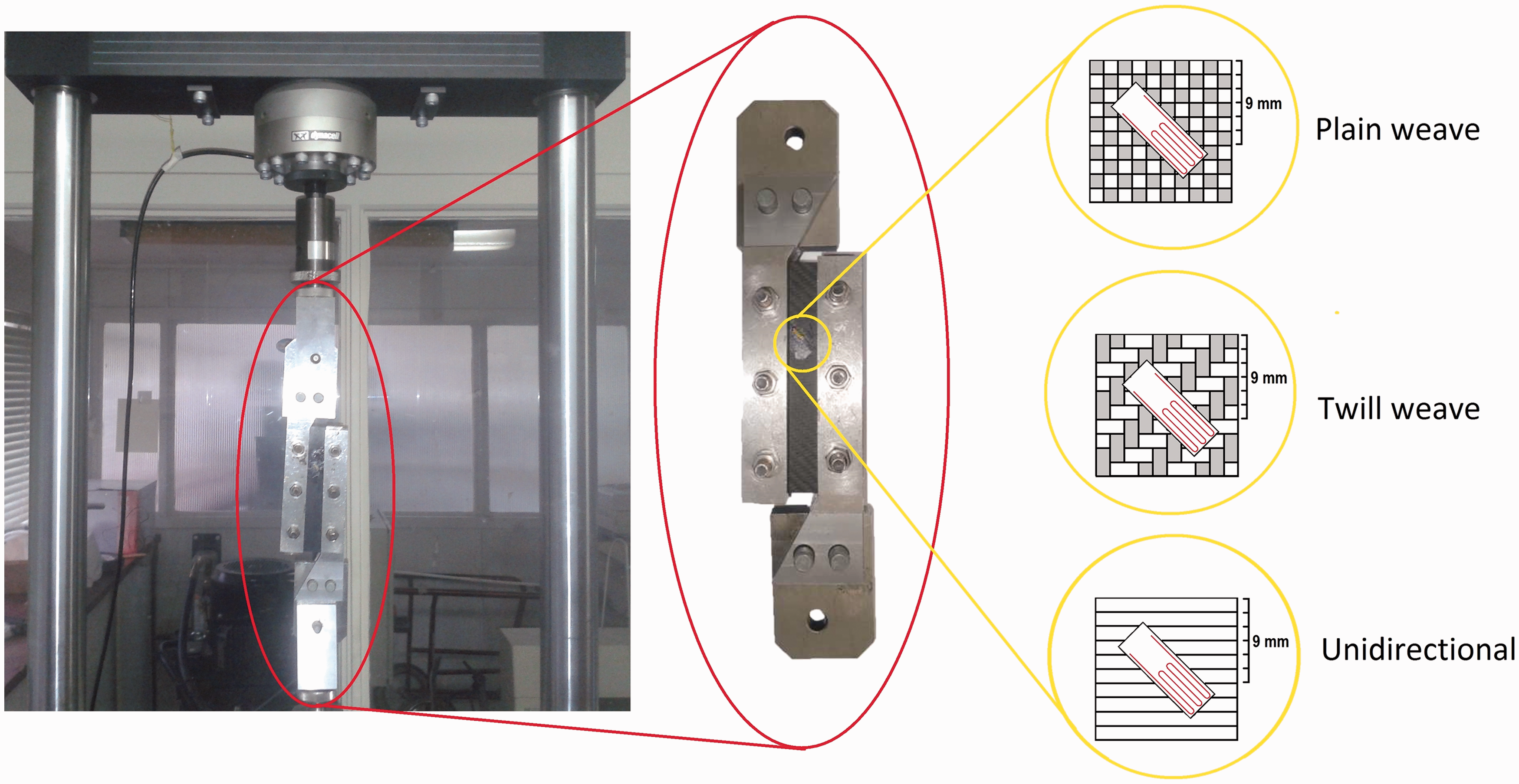
The principal strain direction is verified from an optically performed digital image correlation study (Aramis from GOM Gmbh, Germany) up to a total major strain of 0.05 for all the laminate configurations. In addition, the study was used to check the pure strain shear state, the homogenous strain field at the gage zone, the lack of influence of the edge effect and the negligible bending of the specimen during the test. The study is used to justify the use of a single strain gage in the gage area.
The shear stress is computed from the force, as measured using the data from a 100 kN load cell and the initial cross-section of the specimen.
The data are collected in shear stress–shear strain plots for further analysis.
At least two laminates per configuration were used for testing. Three specimens were obtained from each laminate: one specimen was used for monotonic loading and the other two were used for cyclic loading.
Results
Figure 3 shows the stress–strain relation for the monotonic case, and Figure 4 shows the stress–strain relation for the cyclic conditions performed at equal cross-head relative displacements. Representative curves are chosen for a qualitative comparison.
Results of the monotonic loading tests. Results of the cyclic loading tests.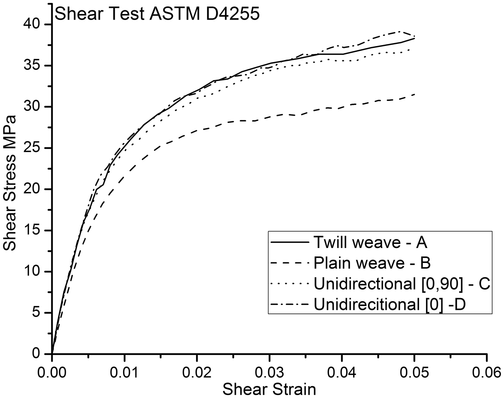
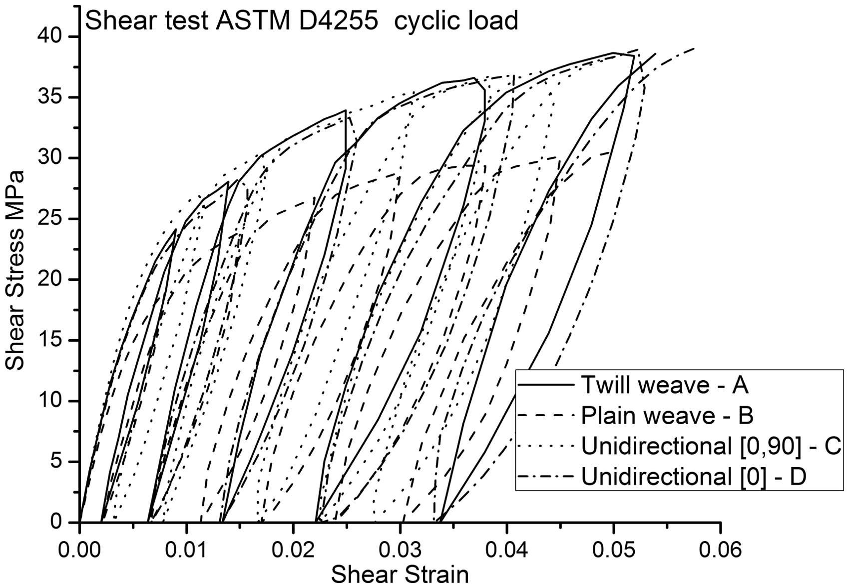
The curves show evidence of elastic-plastic behavior with plastic strain hardening of the material subjected to in-plane shearing. The same behavior was reported in Refs. 6, 9 and 16 for different material constituents. According to O’Dwyer et al., 17 this phenomenon can be attributed to the matrix elastic-plastic behavior (as shown in Figure 1) that permits rotation of the fibers, inducing hardening. Additional experimental evidence of the elastic-plastic behavior of the epoxy resin under quasi-static loading conditions is found in the study by da Costa HS and de Abreu. 18
Laminates A, C and D exhibit similar behaviors for both loading cases and laminate B exhibits the lowest stress levels.
Initial shear modulus.
The subsequent in-plane shear modulus (i.e., in the unload/load paths) is obtained by linear fitting.
9
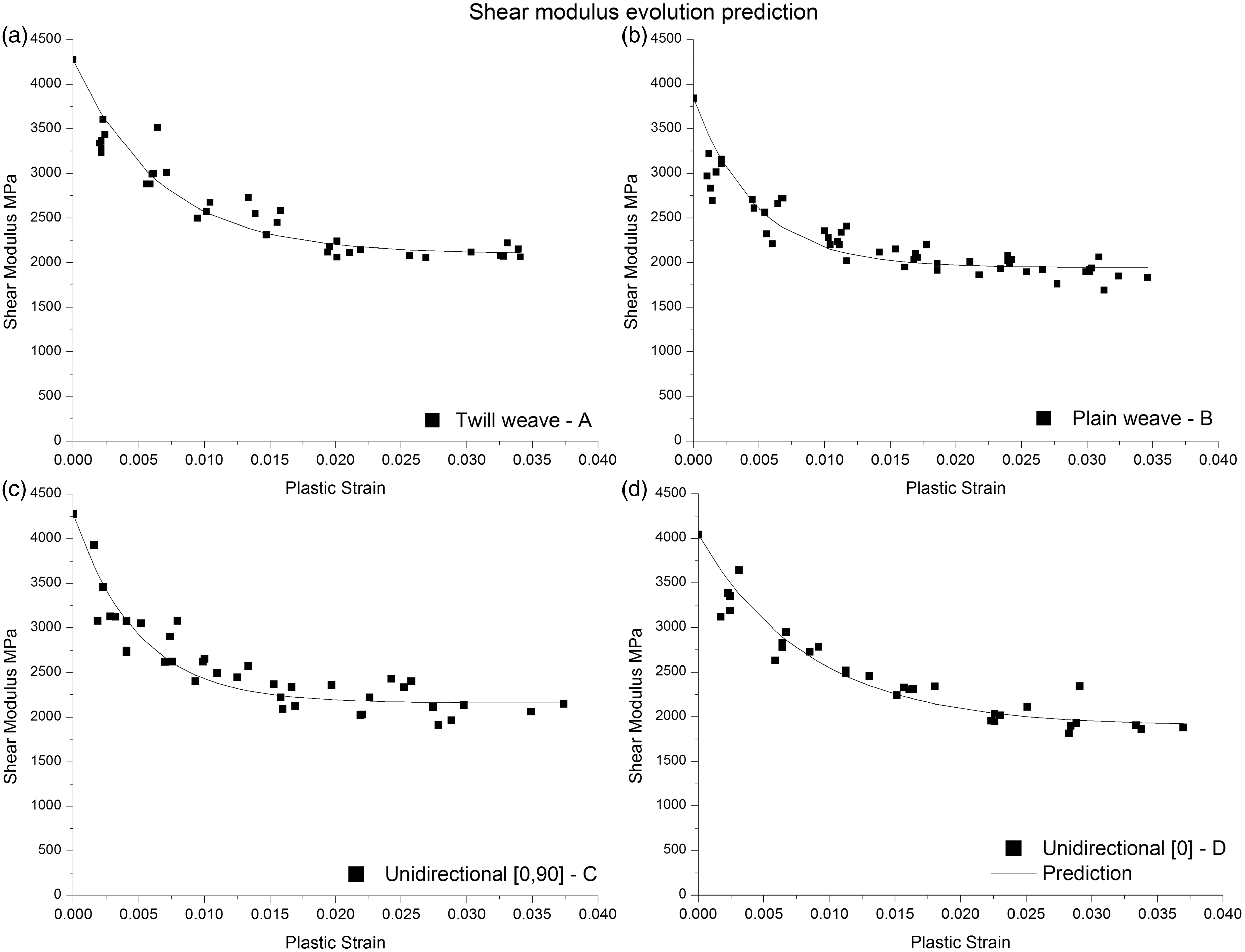
Figure 5 shows the evolution of the in-plane shear modulus in terms of the plastic strain, assuming additive decomposition of the total strain, which is composed of the elastic strain and the plastic strain. For every case, the in-plane shear modulus reaches a steady value.
Evolution of the in-plane shear modulus in terms of the plastic strain: (a) Laminate A, (b) Laminate B, (c) Laminate C and (d) Laminate D.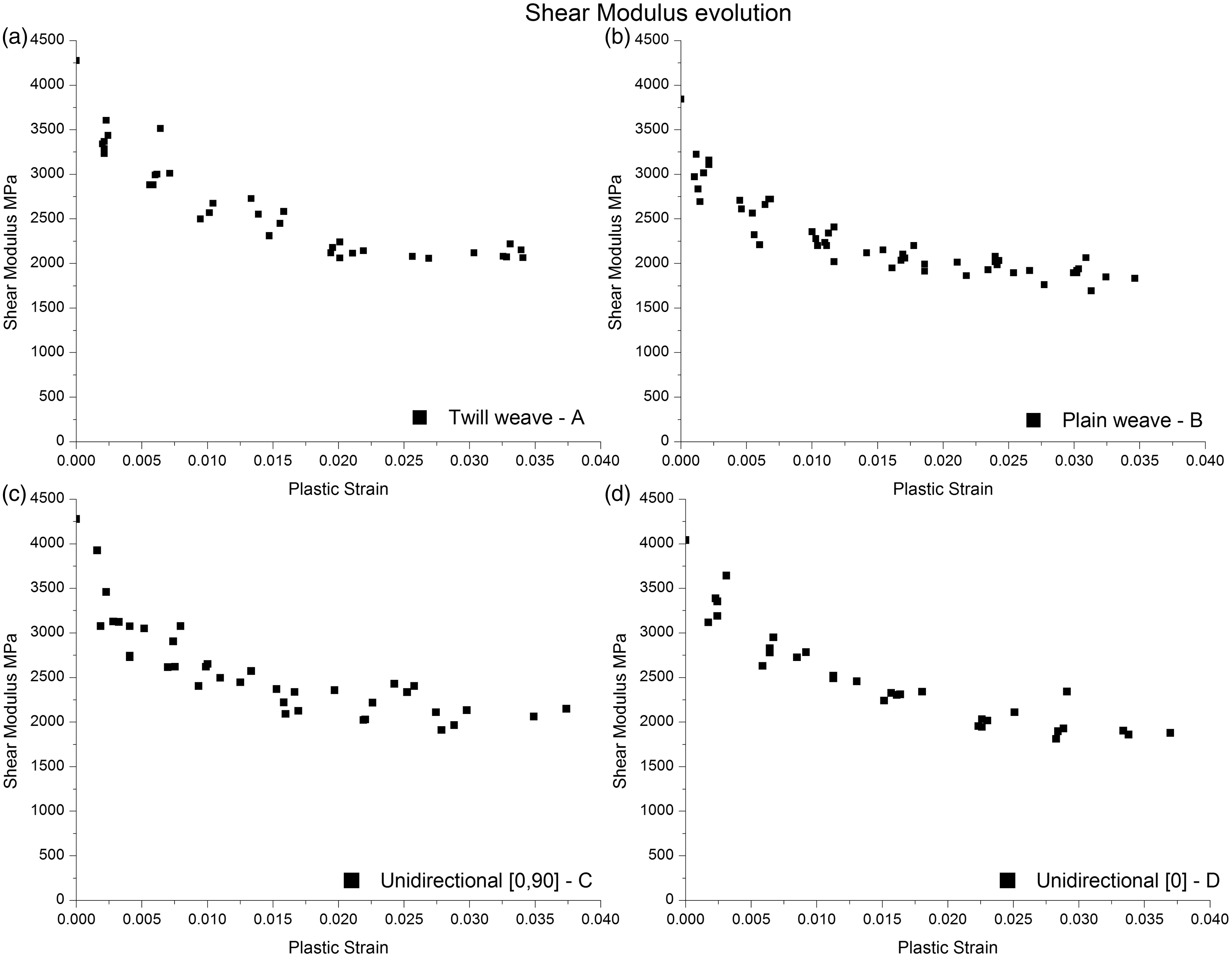
Discussion
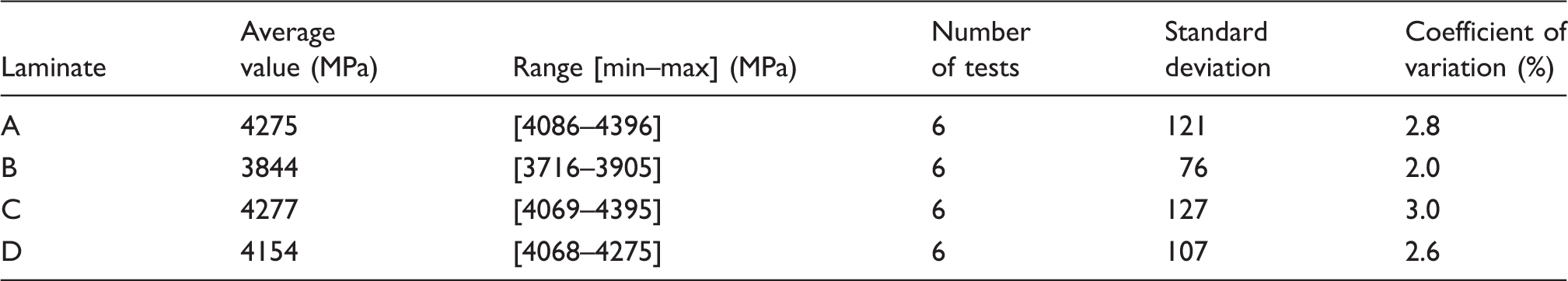
As indicated in Table 3, laminates A, C and D show small variations in the fiber volume fraction and negligible differences in the in-plane shear modulus. Laminate B, which has the lowest fiber volume fraction, possesses the lower shear modulus. These results show that only the fiber volume fraction has an influence. Therefore, the in-plane shear moduli of the laminates examined here do not depend on the reinforcement structure or configuration. These results agree with those obtained by Adumitroaie and Barbero. 2
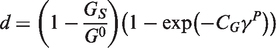
Based on the results in Figure 5, the in-plane shear modulus evolves in terms of the plastic strain until it reaches a steady value. This evolution in terms of the plastic strain is modeled by equation (1), where CG and GS are material parameters that relate the rate needed to achieve the steady level and the steady in-plane shear modulus, respectively. G is the in-plane shear modulus, and γP is the in-plane shear plastic strain.
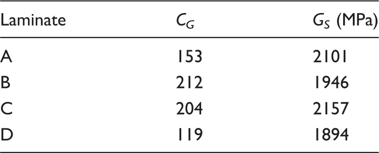
The solution to equation (1) is presented in equation (2), where G0 is the initial in-plane shear modulus. The in-plane shear modulus steady value is taken directly from the experimental curve, and the rate is determined using the least squares method. The values are shown in Table 4, and the functions belonging to each laminate are plotted in Figure 6.
Evolution functions of the in-plane shear modulus in terms of the plastic strain: (a) Laminate A, (b) Laminate B, (c) Laminate C and (d) Laminate D. Parameters describing the evolution of the in-plane shear modulus in terms of the plastic strain.
To compare these phenomena, the in-plane shear modulus is normalized to the initial in-plane shear modulus for each configuration and plotted in Figure 7. The four configurations undergo similar relative reductions in the shear modulus and hence it can be induced that the weave structures lack of influence on the evolution of the modulus.
Normalized evolution of the in-plane shear modulus in terms of the plastic strain.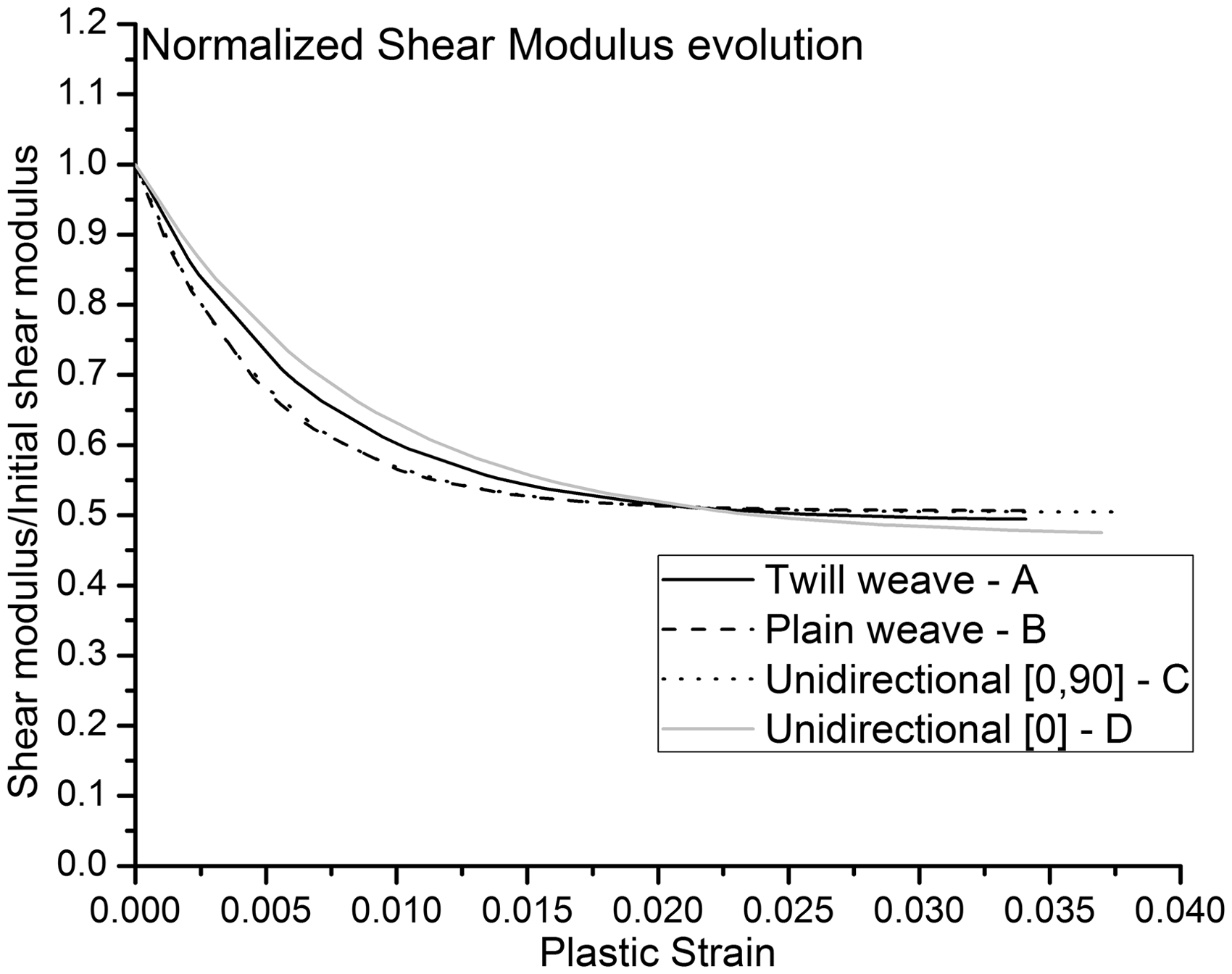
The in-plane shear damage, which is defined as detrimental to the mechanical properties, is usually described by equations (2) and (3) and rewritten as equation (4). Using equation (4), it is straightforward to show that the damage reaches the saturation level, as established by Greve and Pickett
8
and Fouinneteau and Pickett.
9

The differences in strain hardening observed for laminate B with respect to the other configurations (as observed in Figures 3 and 4) can be attributed to the weave structure linked to the scissoring effect
19
or to the difference in the fiber volume fraction. To address the differences in strain hardening, a complementary experiment is performed, in which new laminates with similar fiber volume contents are manufactured to verify the independence of the weave structure with regard to the in-plane shear mechanical behavior. The laminates are manufactured using the resin transfer molding method in rigid aluminum molds at a resin injection pressure of 4 bar. The material matrix is an L20 epoxy resin (by Poxy System) reinforced by the following: (a) twill 2/2 fabric with a density of 204 g/m2 (the same features as TW245 in Table 1) and (b) BI245 fabric (see Table 1). The twill-reinforced composite achieves a fiber volume fraction of 0.54, and the plain reinforced composite reaches a fiber volume fraction of 0.55 (determined using the measurement method described in section “Material manufacturing”). Subsequent mechanical testing is performed as described in section “Mechanical testing”. The in-plane shear stress–strain curve is presented in Figure 8 using representative curves for both configurations, which show similar behaviors. This result indicates that the hardening depends on the composite constituent materials and on their proportion rather than the weave structure for the range of plastic strains studied here.
Stress–strain response of the complementary tests.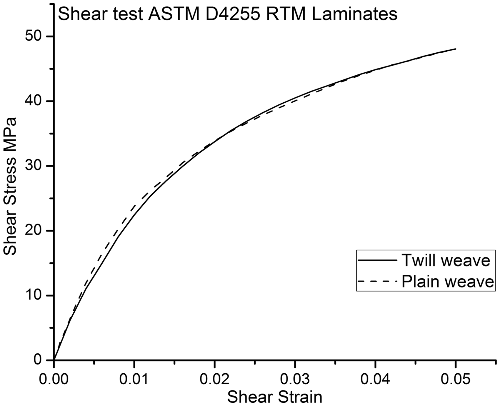
Conclusions
The in-plane shear mechanical behavior based on the shear modulus, strain hardening, damage and ultimate strength (as defined by the standard) depends on the nature of the constituents and on their proportions in the laminate. The weave structure and the laminate configuration do not affect the mechanical behavior, as long as it remains orthogonal.
The damage observed on the materials under the in-plane shear state follows the same pattern: a fast lost on the shear modulus achieving a saturation level. This behavior can be represented by the proposed first-order differential equation.
Footnotes
Funding
This work was supported by Conicyt through the projects Fondecyt de iniciación (11070179) and Conicyt Regional (CIPA/R08C1002).
Conflict of interest
None declared.