






Abstract
Natural plant fibres are short fibres that must be spun into continuous length yarns for the production of structured composites. Fibres in a twisted singles yarn are poorly aligned. The fibre alignment can be improved without sacrificing the yarn strength by forming a two-ply yarn from two singles yarns. In this paper, we analysed the differential geometry of fibre trajectory using an idealised twisted yarn model and derived the optimum two-ply yarn structure that gives the maximum Krenchel fibre orientation factor. In the optimum two-ply yarn, the ply twist is in the opposite direction to the singles twist and the ply-to-singles twist ratio is 0.28. Such a two-ply yarn construction is beneficial for all twisted yarns aimed for structural composites applications, particularly for yarns made from low cost natural fibres which are usually of short length, low strength and poor uniformity and thus require high twist to achieve sufficient strength for yarn manufacture and further handlings in composite fabrication.
Keywords
Introduction
The mechanical properties of a composite are mainly governed by the intrinsic properties of the constituent fibres, the fibre architecture and the fibre–matrix interface. Fibre architecture, including fibre geometry, fibre orientation, packing arrangement and fibre volume fraction, determines many composite properties, particularly mechanical properties.
1
This relationship is exemplified by the ‘rule-of-mixtures’ equation:


There is growing interest in the use of natural plant fibres, such as flax, hemp, kenaf, sisal, ramie, etc., as reinforcement for composites, driven by an increasing environmental awareness and governmental sustainability policy and regulations. Despite the extensive research and development activities around the world in the last two or three decades, current natural fibre composite materials, which are mostly made from random mats, still cannot compete with glass fibre composites in terms of mechanical performance. Unlike conventional continuous length reinforcement fibres, such as glass and carbon rovings, natural fibres are of short length, known as staple fibres in the textile industry. Generally speaking, these natural fibres need to be firstly processed into continuous yarns using conventional textile spinning processes before being made into highly directional reinforcements for use in structural composites, 3 although research on unidirectional nonwoven preforms has been undertaken. 4
The staple fibres in a conventional twisted yarn are held together by the fibre-to-fibre friction derived from the helical fibre path (i.e. twist) formed during spinning. The dominating technology used to produce twisted yarns is the conventional ring spinning method. The strength of a twisted yarn is highly dependent on the appropriate choice of twist. The simplest geometrical model of twisted yarns is the coaxial helix structure proposed by Gégauff in 1907,
5
which is shown in Figure 1(a). The model has been widely adopted with only minor modifications in modern yarn structural mechanics analysis.
6
Coaxial helix model of singles yarn structure. The amount of twist is expressed by the inclination angle β(r), which is a function of the fibre distance r from the yarn centre axis. The fibre length in the unit length yarn cell is indicated by the red line L.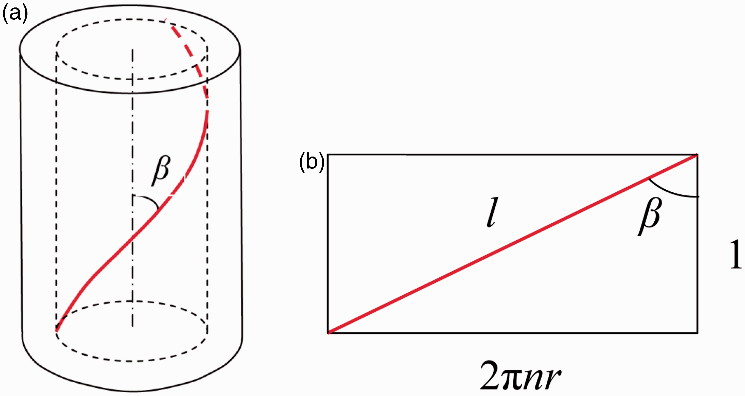
In conventional staple fibre yarns, twist has a profound influence on the yarn strength. At low twist levels, the fibres are aligned with the yarn axis, but the friction between fibres generated by the twist is low. Fibres can slip over each other and thus the yarn fails due to fibre slippage. At high twist levels, the fibres are inclined with respect to the yarn axis and therefore fibre slippage is largely prevented by high fibre-to-fibre friction. The yarn fails due to fibre breakage. In addition, high twist reduces the contribution of fibre strength to the yarn strength due to fibre obliquity in relation to the yarn axis in a similar way as the Krenchel fibre orientation factor for composites. This yarn twist–strength relationship is shown schematically in Figure 2.
Influence of twist on tensile properties of short-fibre yarns.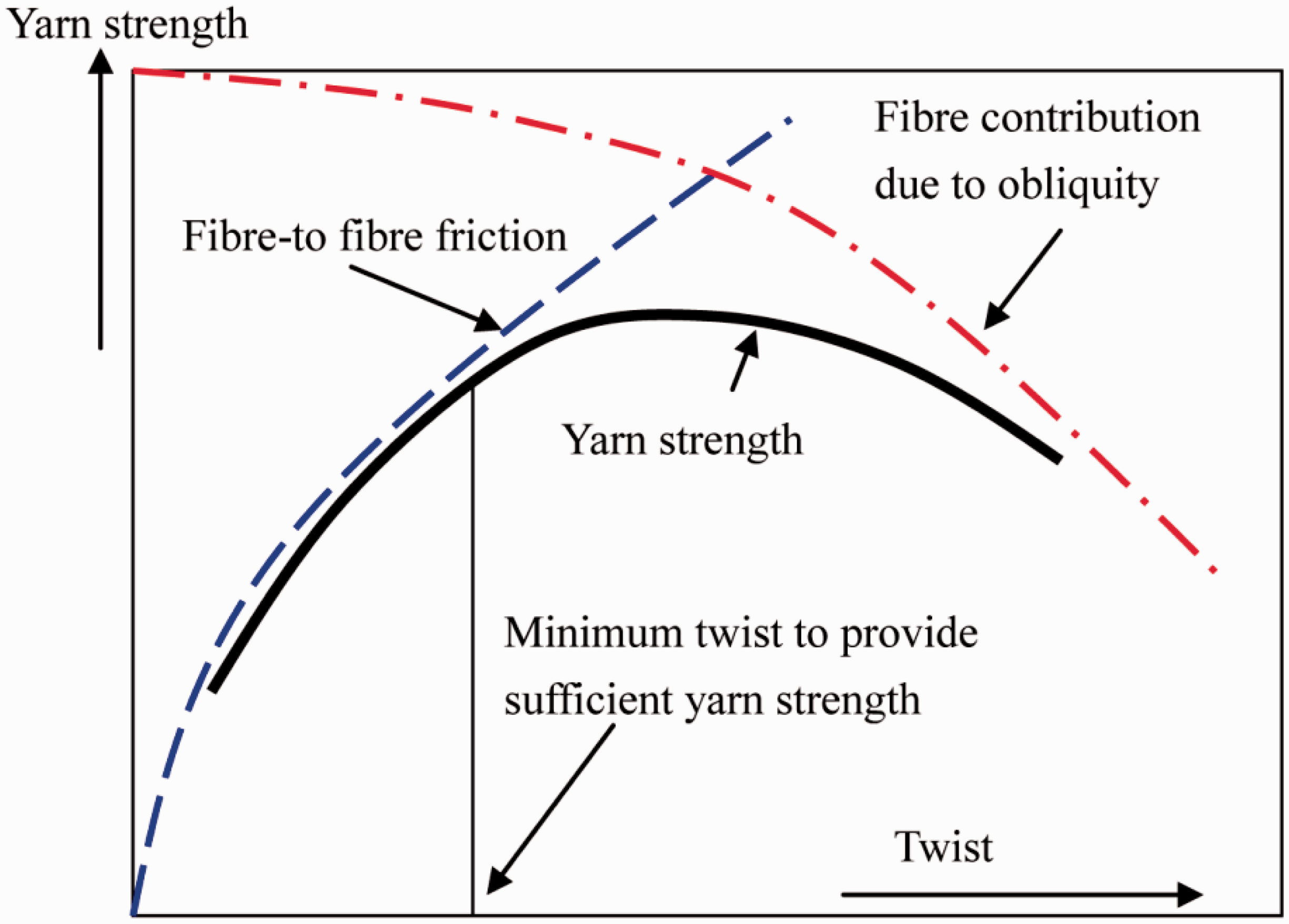
In fibre-reinforced composites, interfacial bonding between the fibre and the polymer matrix provides the load transfer mechanism, so the yarn strength created by the friction between fibres in the dry yarn is only needed for yarn handling during yarn and composite fabrication processes. Once the fibres are fabricated into the final composite, the fibre helical path in the twisted yarn contributes negatively to the composite mechanical properties, as indicated by equation (2). Another negative impact of yarn twist is that it tightens the yarn structure and thus increases the difficulty of resin impregnation. For these reasons, Goutianos, et al. 7 attempted to balance the processing requirements on the yarn (which requires a reasonable degree of twist) and the mechanical properties of the final composites (which require as little twist as possible) so that only the minimum level of twist was inserted into the yarn to meet the processing requirements. However, the minimum strength dry yarn still requires a significant level of twist, which means a low fibre alignment, and consequently a low utilisation of fibre mechanical properties in the final composites.
In fact, the fibre angles in twisted yarns can be reduced without sacrificing the yarn strength by making a two-ply yarn structure. To make a two-ply yarn, two identical singles yarns are put together in parallel (yarn-folding) and are then twisted (ply-twisting) in a direction that is opposite to the twist direction of the initial singles yarns. Two-plying is a technique commonly used in the textile industry to increase yarn strength, to reduce yarn twist liveliness (a twisted yarn has a built-in torque and tends to release its twist if one end of the yarn is set free), to improve yarn abrasion resistance (attrition of loosely bonded fibres on yarn surface when being rubbed against another surface) and to achieve desirable visual effect (for example, the highest fabric lustre is achieved when all fibres on the yarn surface are approximately parallel to each other). Obviously, the desired level of opposite twist imparted in the two-ply yarns must be set according to with the yarn properties that are targeted to achieve.
Because the twist angle of fibres in a singles yarn varies from zero (at the yarn centre) to a maximum (on the yarn surface), the opposite-direction ply twist cannot turn all fibres to the direction parallel to the ply-yarn axis. By varying the degree of ply-twist, some fibres in the singles yarn can be turned to the direction parallel to the two-ply yarn axis while fibres at other positions in the yarn cross-section are at reduced angles to the two-fold yarn axis, resulting in an improved overall fibre alignment along the two-ply yarn axis. The aim of this study is to determine the ply twist required to achieve the maximum fibre orientation in the two-ply yarn, using the Krenchel fibre orientation factor in equation (2) as an indicator.
Krenchel orientation factor of singles yarns
Most plant fibres used in composites (known as technical fibres) are in the form of bundles or strands of fibre cells held together by a natural matrix. The fibre cell in turn consists of cellulose fribrils (nanometre in diameter scale). The fibrils follow helical paths around the cell axis, similar to the paths of fibres in a twisted yarn. The helical angle of the fibril varies in direction and magnitude according to the position of the fibril in the cell wall, the position of the cell in the plant from pith to bark and the type of plant.8,9 These angular differences introduce variations in fibre mechanical properties. The yarn geometrical model in this paper will consider the placement of the technical fibres, rather than their internal components, such as the bundled cells within a technical fibre or the angularly positioned fibrils inside the cells.
The idealised coaxial helix yarn structural model proposed by Gégauff 5 shown in Figure 1(a) will be adopted for the singles yarn. The singles yarn is assumed to be circular in cross section and composed of a series of concentric cylinders of differing radii. The fibre packing density in the yarn is assumed to be constant. Each fibre follows a helical trajectory with a constant helix angle (β) around one of the concentric cylinders. Because the number of twist turns per unit yarn length (n) remains the same for all helices irrespective of their radii, the helix angle β increases as the position of the helix going out from the yarn centre.
By cutting one of the concentric cylinders along a line parallel to the yarn axis and then opening the cylinder out flat,
6
we obtain a rectangle in which a fibre lies diagonally, as shown in Figure 1(b). By definition, a unit cylinder length contains n turns of twist (2πn in radian). The helix angle (or twist angle) β at an arbitrary radius r and the fibre length l in the unit length yarn can therefore be calculated using the following relationships:


In the textile industry, yarn linear density is expressed in tex (1 tex = 1 g/km = 1 mg/m) and yarn count (length in a unit mass of yarn, i.e. the reciprocal of linear density), instead of yarn diameter. Since yarn linear density is proportional to the yarn cross-sectional area (πR2, where 2R = yarn surface diameter) for a given yarn volume density, the twist angle of yarn surface fibres α = β (R) can be expressed in terms of yarn linear density, i.e.

Madsen et al.
10
derived the mean fibre twist angle in such an idealised singles yarn:


The Krenchel fibre orientation factor for a singles yarn in equation (6) is plotted as a function of its surface twist angle (α) in Figure 3. Clearly, fibre alignment in a singles yarn reduces with the increase of yarn twist. Yarns made from short fibres do not have adequate strength for handling unless a sufficient level of twist is applied. So the twist required for achieving sufficient yarn strength for processing determines the level of fibre alignment (Krenchel fibre orientation factor) of the singles yarns.
Relationship between yarn surface twist angle and Krenchel orientation factor for singles yarns.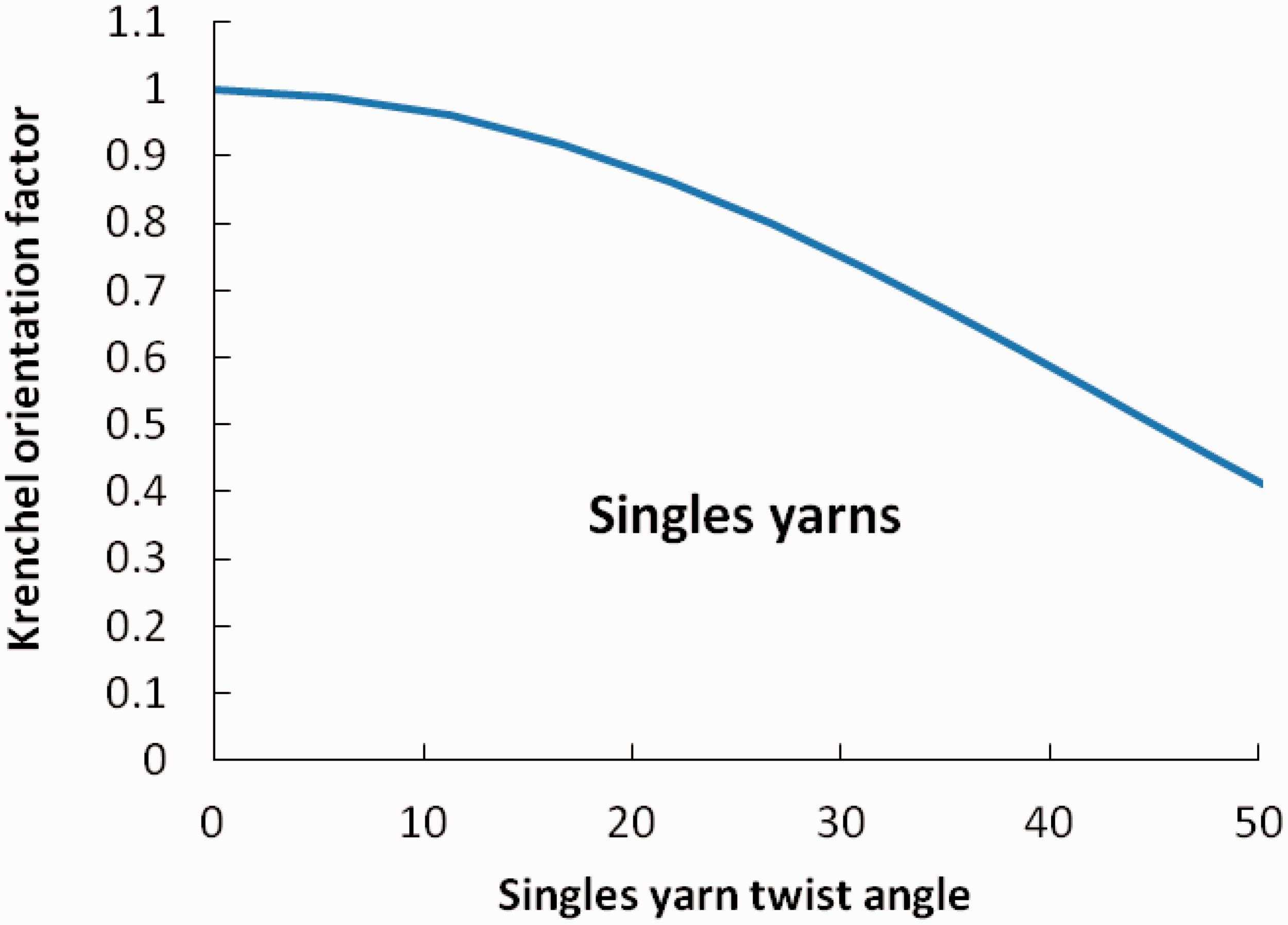
Two-ply yarns
A two-ply yarn is shown schematically in Figure 4. The axes of the two singles yarns follow two separate helical paths with the same helix angle determined by the two-ply twist and the radius of the singles yarns R. The ply twist, N (turns/m), is in opposite direction to the singles twist n. As a first approximation, we further assume that the singles yarn cross section (perpendicular to the singles yarn axis) maintain its circular shape and the yarn radius remains the same after the two singles yarns are converted into a two-ply yarn.
Schematic of an idealised two-ply yarn and its cross section.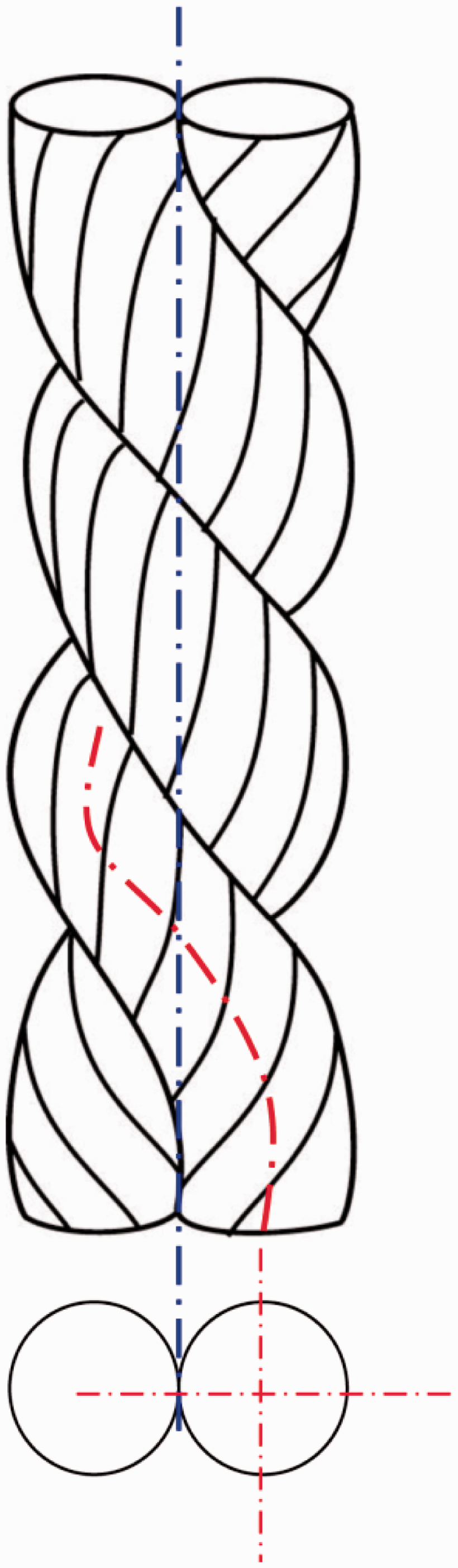
As shown in Figure 5(a), we establish a fixed coordinate frame OXYZ, in which Z-axis coincides with the axis of the ply yarn (i.e. the blue line of contact between the two singles yarns in Figure 4). The centres of the two singles yarn cross sections are at (−R, 0) and (R, 0) in the XY plane (i.e. the plane Z = 0), respectively, where R is the radius of the singles yarns. As the two singles are geometrically symmetrical about the Z axis, we need only to analyse one of the singles yarns, i.e. the singles yarn with its centre at (R, 0) in the XY plane.
Fixed and moving coordinate frames.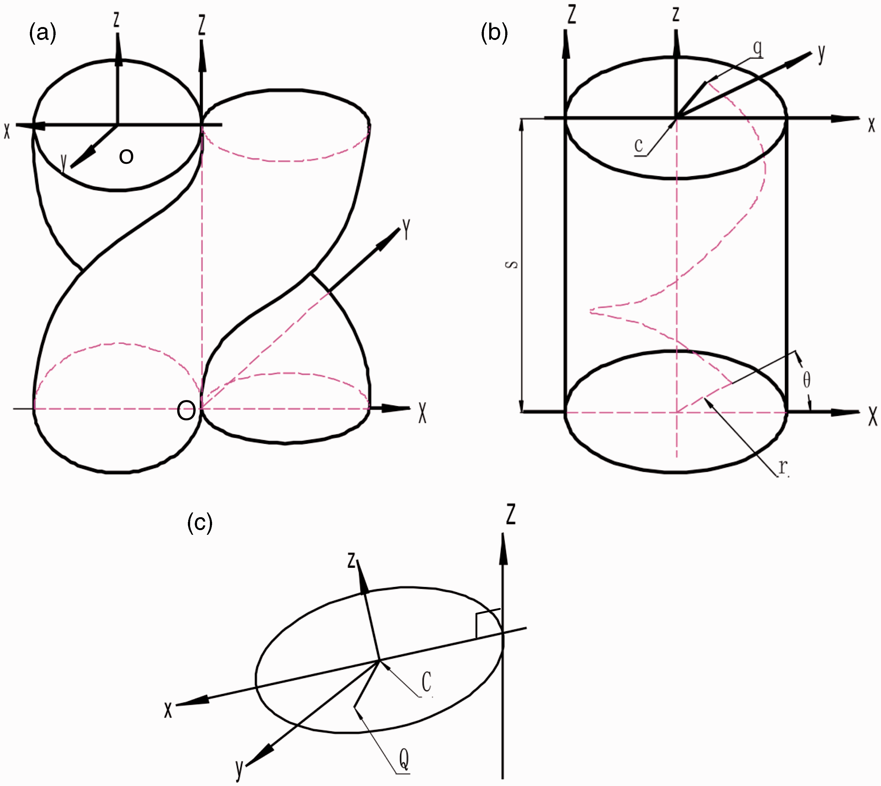
We further establish a moving coordinate frame oxyz with its origin o moving along the helical path of the singles yarn axis. The z-axis of the moving frame coincides with the tangent of the singles yarn axis. Obviously, the singles yarn cross section is in the xy plane, which is perpendicular to the z-axis. Its x-axis coincides with the singles yarn radius that intersects with the Z-axis (i.e. ply yarn axis) of the fixed coordinate frame OXYZ in the direction pointing towards the origin of the moving coordinate o, as shown in Figure 5(a). We will use capital letters to denote positions, vectors and other parameters in the fixed coordinate frame OXYZ and small letters to denote parameters in the moving coordinate frame oxyz.
Before the two singles yarns are twisted into a plied yarn, the singles yarn axis, z-axis, is parallel with the ply yarn axis, Z-axis. After a ply twist N is inserted, the singles yarn axis is turned into a helix around Z-axis. The vector position of the origin of the moving coordinate frame oxyz, o in the moving frame, is point C in the fixed coordinate frame OXYZ, where

This describes the helix path of the singles yarn axis in the two-ply yarn. Note that the origin of oxyz is denoted as c in Figure 5(b) to be consistent with the corresponding position C in fixed coordinate frame. The tangent of the helix at point C in the fixed coordinate frame can be derived by differentiation of equation (7) with respect to Z:

The vector from Z-axis to C in the Z-plane (i.e. the plane Z = Z) is

The two vectors
Because point C coincides with the origin o and
The helix angle φ of the singles yarn axis (


This tells us that the insertion of the ply twist N, i.e. the transform of the moving coordinate frame to the fixed coordinate frame, may be treated as a two-step process: (1) a first rotation of angle φ around its x-axis and (2) a second movement rising along the helix (with a constant helix angle φ given by equation (11)) around the Z-axis of the fixed coordinate frame OXYZ.
In Figure 1(b) and equation (3b), if we let the helix radius be R, height be Z and the twist level be N, we can get the length (s) of the helix formed by the singles yarn axis in the two-ply yarn:


And let q be the position of the intersection of this fibre trajectory with the upper cross section of the singles yarn segment. The vector from the singles yarn centre c to q in the moving coordinate oxyz is


We get

From equations (7) and (15), we obtain the position vector Q in the fixed coordinate frame

The tangent vector of the fibre trajectory at position Q can be found by differentiation of the above equation with respect to Z

And from equations (11) and (12), we get


Substituting these relationships into equation (17) gives
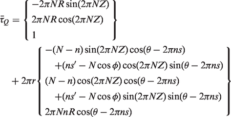
Carry out the following operations:


Substituting equations (11) and 18(a) into equation (21), we get

The angle between

The Krenchel orientation function P(r, θ) for this fibre trajectory at point Q is therefore

Because we have assumed that all fibres are uniformly distributed across the singles yarn cross section, the mean Krenchel orientation factor across the singles yarn cross section,

Because s is independent of θ (equation (12)), and for any function F[cos(A + θ)], it can be proven that
Equation (25) can therefore be simplified to:

Let

Numerical results and discussion
The mean Krenchel fibre orientation factor of two-ply yarns, Influence of ply/single twist ratio (λ = N/n) on Krenchel fibre orientation factor of two-ply yarn. Krenchel fibre orientation factor for optimum two-ply yarn, singles yarn and conventional two-ply yarns.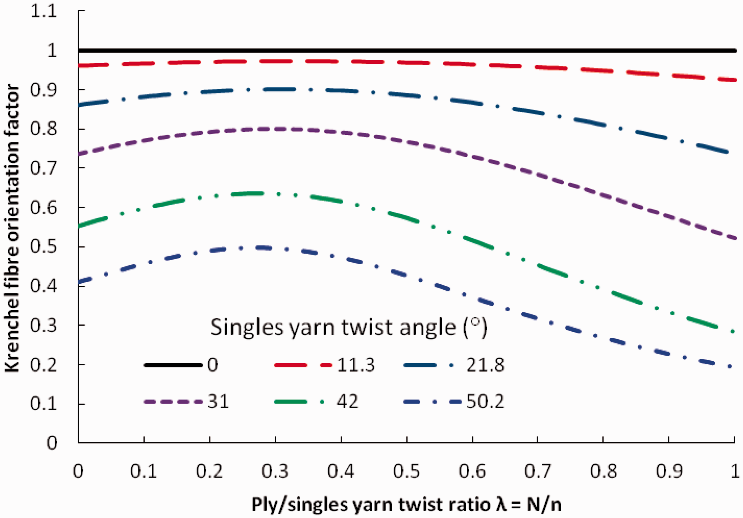
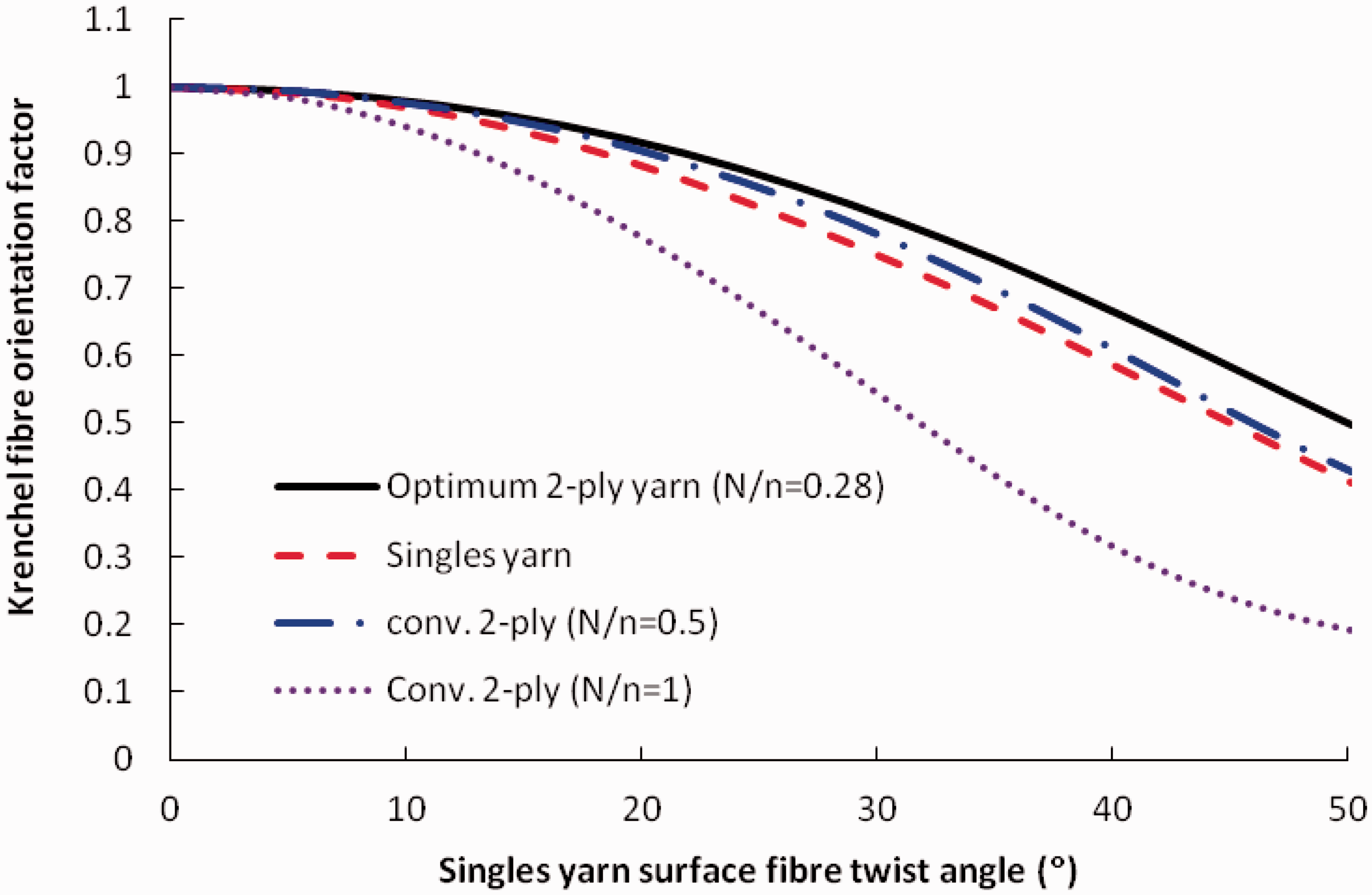
Figure 6 shows the influence of the ply/singles twist ratio λ on the Krenchel fibre orientation factor of two-ply yarns at selected levels of singles yarn twist. The level of singles yarn twist has an important impact on the fibre orientation of the final two-ply yarn, no matter what level of ply twist is used. The Krenchel fibre orientation factor in the two-ply yarn gradually improves with increasing ply/singles twist ratio λ and reaches its plateau at λ ≈ 0.28 irrespective of the twist level (n) and diameter (2R) of the parent singles yarns. This provides a very simple rule of thumb for constructing optimum two-ply yarns for structural composite applications. Too much of ply twist (λ > 0.28) reduces the Krenchel fibre orientation factor.
As mentioned earlier, twist factor, instead of twist turns and twist angles, is traditionally used in the textile industry. Because the two-ply yarn has approximately twice the linear density of the constituent singles yarn, from equation (4), the ply/singles yarn twist ratio of 0.28 corresponds to a ply/singles yarn twist factor ratio
Figure 7 compares the Krenchel fibre orientation factors of singles yarns, conventional two-ply yarns (twist ratio λ = 0.5 and 1.0, or twist factor ratio 0.7 and 1.4, respectively) and the optimum two-ply yarns for composites derived in this paper (λ = 0.28 or twist factor ratio 0.4). The fibre orientation factor values for singles yarns were calculated from equation (27) by letting λ = 0 (i.e. zero ply twist, i.e. two singles yarns are simply laid in parallel). These values are the same as those in Figure 3 calculated from equation (6) based on the singles yarn model. For the conventional two-ply yarns, at low ply/singles twist ratio (λ = 0.5, or twist factor ratio 0.7), the fibre alignment is marginally better than its parent singles yarns. At high ply/singles twist ratio (λ = 1.0, or twist factor ratio 1.4), the fibre alignment in the conventional two-ply yarn is far worse than its parent singles yarn. The fibre alignment in the optimum two-ply yarn is superior to these three conventional yarn constructions. When compared by relative values, improvement = (ηopt 2-ply – ηconv)/ηconv, the optimum two-ply yarn shows up to 21.5% improvement in fibre orientation over its parent singles yarn, up to 16.6% improvement over the low twist conventional two-ply yarn (λ = 0.5), and up to 159% improvement over the high twist conventional two-ply yarn (λ = 1.0).
The Krenchel fibre orientation factor of the optimum two-ply yarn structure (i.e. λ = 0.28) in Figure 7 shows that fibre alignment in the optimum two-ply yarn deteriorates as the parent singles yarn twist increases. At a relatively low singles yarn surface twist angle of 20°, the Krenchel fibre orientation factor of the optimum two-ply yarn was about 10% lower than a twistless yarn (zero-twist singles yarn, which has the maximum Krenchel fibre orientation factor of 1.0, as shown by the horizontal straight line in Figure 6). In a highly twisted yarn (singles yarn surface fibre twist angle 50°), the Krenchel fibre orientation factor drops to about 50% of that of the twistless yarn. It is therefore very important to keep the singles yarn twist as low as possible. In practice, the minimum singles yarn twist required for ring spinning depends on the spinnability of the fibre (such as fibre length, strength and uniformity), quality of fibre preparation, spinning equipment and production management practice. Higher twist is usually required for spinning lower quality fibres that are shorter, weaker or less uniform. Insufficient twist will result in low yarn strength, frequent yarn breakage and machine stoppage during spinning and further processes, leading to lost productivity and high labour cost for mending yarn breakage. Because spinning is a costly process, yarn manufacturers always try to strike the right balance between fibre quality (i.e. fibre price) and yarn twist (labour cost).
The two-ply yarn geometry model used in this paper is based on a number of assumptions. The errors caused by these assumptions can best be determined by comparing the predicted results with experimentally determined results in future studies.
Conclusions
Natural plant fibres are only available as short fibres. For the production of structural composites, natural fibres need first to be spun into continuous singles yarns, usually by insertion of twist. Fibre paths in a twisted singles yarn (approximately co-axial helices) are poorly aligned with respect to the yarn axis. The fibre orientation can be improved without sacrificing yarn strength by forming a ply yarn from two identical singles yarns. We analysed the orientation of fibres in an idealised two-ply yarn structure model using differential geometry and derived the optimum two-ply yarn construction that gives the maximum Krenchel fibre orientation factor. The optimum ply twist is equal to 28% of the singles twist and is opposite in twist direction. In practice, yarn manufacturers should first spin singles yarns at the lowest possible twist level and then produce a two-ply yarn from the singles yarn at the optimum ply/singles twist ratio of 0.28. This method is particularly suitable for spinning low cost natural fibres which are usually of short length, low strength or poor uniformity and therefore require high singles yarn twist to achieve sufficient yarn strength for efficient handling in spinning and further processes.
Footnotes
Conflict of Interest
None declared.
Funding
This research received no specific grant from any funding agency in the public, commercial, or not-for-profit sectors.