
Abstract
Material property characterization tests were performed on satin weave carbon/epoxy composites, where the epoxy resin was modified with 2 wt% carbon nanofibers prior to infusion into a continuous carbon fiber preform. Uniaxial tension tests, tension-tension fatigue tests, and fracture tests were initially performed on 0–3 wt% carbon nanofibers-reinforced epoxy specimens in order to determine the carbon nanofiber weight fraction leading to the optimal mechanical properties of the modified epoxy matrix. In general, the elastic modulus of the modified epoxy increased with increasing carbon nanofibers weight fraction. The ultimate tensile strength, fatigue life, and fracture toughness also increased significantly with increasing amounts of carbon nanofibers and reached maximal values at a carbon nanofiber weight fraction of 2 wt%. The improvement in tensile properties of carbon nanofiber–modified epoxy became more pronounced for specimens loaded at higher strain rates. Further increases in nanofiber content, however, resulted in a relative decrease in nanocomposite strength and fatigue life; this is likely due to local stress concentrations associated with poorly dispersed carbon nanofibers. Vacuum-assisted resin infusion molding was used to fabricate hybrid composite panels consisting of woven carbon fabric and epoxy resin modified with 2 wt% carbon nanofibers. Uniaxial compression, open-hole compression, and short beam shear tests were performed to assess the effect of carbon nanofibers on matrix-dominated composite properties. Hybrid composites containing 2 wt% of carbon nanofibers in the epoxy matrix resulted in compressive strength, open-hole compressive strength, and interlaminar shear strength values that were 19.8%, 27.8%, and 15.8% greater, respectively, than those for woven fabric composites prepared with neat epoxy. Quasi-static uniaxial tension tests and tension-tension fatigue tests of hybrid composite specimens also led to similar enhancements in the composite ultimate strength and fatigue life relative to composites specimens infused with neat epoxy. Scanning electron microscopy images of composite micro-fracture surfaces indicated that randomly distributed carbon nanofibers provide some crack bridging, reduce crack opening, and lead to crack turning for small cracks. Such mechanisms are likely responsible for the improvement in mechanical properties.
Introduction
Due to their high specific strength and specific moduli, fiber-reinforced epoxies have become attractive lightweight structural materials in aerospace, marine, armor, automotive, railway, civil engineering, and sporting goods applications. In general, the in-plane tensile properties of a fiber/polymer composite are defined by the fiber properties, while the in-plane compression strength and inter-laminar properties are defined by the characteristics of the matrix. Epoxy is the most commonly used polymer matrix for advanced composite materials. Over the years, many attempts have been made to modify the properties of epoxy by the addition of either rubber particles1,2 or inorganic particulate fillers3,4 in order to improve the matrix-dominated composite properties. The addition of rubber particles improves the fracture toughness of epoxy but results in a decreased moduli and strength. The addition of inorganic particulate fillers, however, improves the modulus and strength of epoxy, but decreases the fracture toughness. The heat-deflection temperature of epoxy is also improved by the addition of fillers. 5
In recent years, micro- and nanoscaled reinforcements have been used to modify epoxy to produce high-performance composites with enhanced properties. For example, Wang et al. 6 used SiC whiskers along the interface between composite lamina during the lay-up process to improve the interlaminar fracture toughness. Tasi et al. 7 modified unidirectional carbon/epoxy prepregs by using very thin alumina platelets. Chisholm et al. 8 observed a 39% enhancement in flexural strength by infusing 1.5 wt% SiC nanoparticles in carbon/epoxy composite. Gojny et al. 9 reported the influence of epoxy modified with carbon nanotubes on the mechanical and electrical properties of conventional fiber-reinforced composites.
The primary objective of this paper is to determine the effect of adding vapor-grown carbon nanofibers (CNFs) on the mechanical properties of epoxy and carbon/epoxy composites. Vapor-grown CNFs are distinct from polyacrylonitrile or mesophase pitch-based carbon fibers (CFs) in their method of production, physical properties, and structure. CNFs are attractive nanoscale polymer reinforcements due to their high tensile strength, modulus, and relatively low cost. Thermoplastics (polypropylene, 10 polycarbonate, 11 nylon 12 ), thermosets (epoxy13,14), and thermoplastic elastomers (butadiene-styrene diblock copolymers 15 ) have been reinforced with CNFs. Previous results indicated that the addition of small amounts of CNFs (<3 wt%) to a matrix system can increase thermal, mechanical, and electric properties without compromising the processability of the composite. 16 These polymer-based nanocomposites derive their enhanced properties at low filler volume fractions due to the high aspect ratio and high surface-area-to-volume ratio of the nanosized particles. According to Reynaud et al., 17 a reinforcement interface 1 nm thick represents roughly 0.3% of the total volume of a polymer composite filled with micro-sized particles, whereas such an interface can comprise 30% of the total volume in the case of nanocomposites. However, their high specific surface area causes a strong tendency for CNF agglomeration, which leads to high local stress concentrations and a reduction in nanocomposite strength. Optimal loading of well-dispersed CNFs in the matrix is central to development of nanofilled structural composites. 18
In this study, tensile, fatigue, and fracture tests were performed on epoxy modified with various amounts of CNFs. After the optimal CNF loading was determined, the CNF-filled epoxy matrix was used with a satin weave carbon fabric to fabricate composite panels. Compression, open-hole compression, and short beam shear tests were performed to evaluate matrix-dominated properties, and tensile and tension-tension fatigue tests were performed to evaluate fiber-dominated properties.
Materials and processing
A commercially available SC-15 epoxy resin obtained from Applied Poleramic, Inc, was used in this study. It is a low-viscosity, toughened two-part epoxy resin. The part A is a mixture of diglycidyl ether of bisphenol-A (60–70%), aliphatic diglycidyl ether (10–20%), and a toughener (10–20%). The part B consists of cycloaliphatic amine (70–90%) and polyoxyalkylamine (10–30%). SC-15 is cured at room temperature and is used in vacuum-assisted resin infusion molding processes (VARIM). The PR-24PS carbon nanofibers were obtained from Applied Science, Inc. In PR-24, the fiber diameter ranges from 60 to 200 nm, and the fiber length ranges from 30 to 100 µm. Satin weave carbon fabric, manufactured by Fiber Materials Inc., was used in this study. It is a 11 × 11 weave (11 × 11 indicates that in 1 sq. in. of the fabric area, 11 CF tows are oriented in the warp direction and 11 CF tows are oriented in the fill direction); the fabric thickness was 0.5 mm. The fabric weight was 10-oz./ square yard.
Figure 1(a) and (b) show scanning electron microscopy (SEM) images of as-received CNFs at different magnifications. High specific surface area and cotton-like entanglement of CNFs cause the formation of agglomerates.
19
CNF agglomerates (i.e. “nanoropes”) are difficult to separate and infiltrate with resin. For polymer matrix nanocomposites, high-power dispersion methods, such as ultrasonication and high shear mixing, are the simplest and most convenient methods to improve the dispersion of nanosized fillers in a polymer matrix.20,21 In this study, the constituents were mixed using a high-intensity ultrasonic processor. The CNFs and part A of epoxy were first mixed by hand in a glass beaker. The ultrasonication mixing was performed in pulse mode (50 s on/ 25 s off) using high intensity ultrasonic irradiation (Ti-horn, 20 kHz Sonics Vibra Cell, Sonics Mandmaterials, Inc., USA) for 1.5 h. To avoid a temperature rise during the sonication process, the beaker was submerged in an ice bath. Once the ultrasonication was complete, part B epoxy was mixed with the CNF-filled part A using a high-speed mechanical stirrer for about 10 min. The mixture ratio of CNF-filled part A and part B was 10 to 3. The intense mixing of part A and part B produced bubbles, which could detrimentally affect the properties of the final product by creating voids. To reduce void formation, a high-vacuum pressure was applied using a Brand Tech Vacuum system for about 30 min. After the bubbles were completely removed, the mixture was transferred into a metal mold coated with Frekote release agent and kept for 24 h at room temperature. All as-prepared panels were post-cured at 100℃ for 5 h in a Lindberg/Blue mechanical convection oven. The cured material was then de-molded and trimmed. Finally, test coupon samples were machined for testing.
SEM pictures of as received CNFs at the magnification: (a) ×200 and (b) ×5000.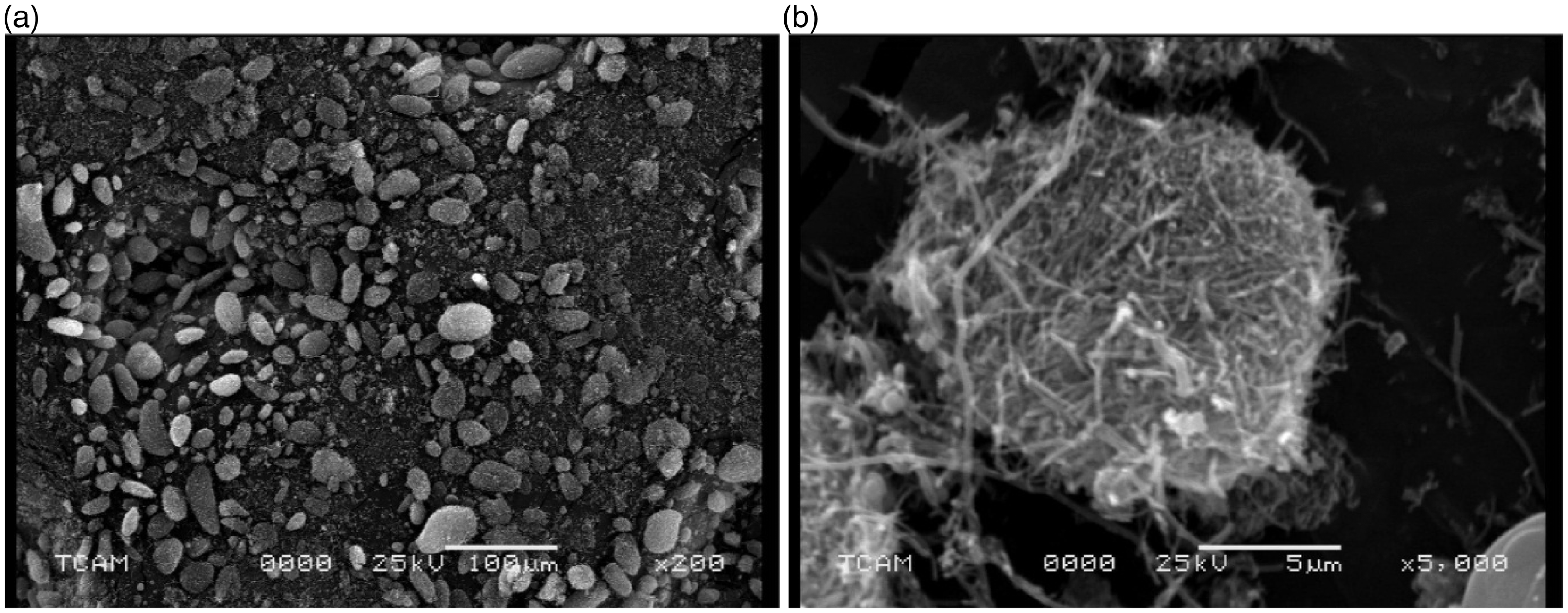
Laminated composite panels were manufactured by using VARIM. A schematic diagram of the manufacturing process is shown in Figure 2. An aluminum plate was laid on a flat surface and cleaned with acetone. A mold release agent (Frekote) was applied to the surface to allow easy release of the panel. To facilitate uniform resin distribution, a layer of distribution mesh was laid on the plate followed by a layer of perforated Teflon sheet. Four layers of dry fabric preforms with required orientations were then laid out on the top of perforated Teflon sheet. Another layer of perforated Teflon sheet and distribution media were laid on the fabric preforms. After stacking, the complete assembly was covered with a leak-proof, heat-resistant vacuum bag, and infusion and suction lines were installed. Resin was infused from one end of plate, and the other end was connected to a vacuum pump. The vacuum bagging is critical in composite manufacturing. After curing, final test samples were machined for mechanical characterization. All panels were cured at room temperature for 24 h and then post-cured at 100℃ for 5 h. Using this technique, carbon/epoxy panels with and without CNFs were fabricated in order to assess the effect of CNFs on bulk composite mechanical properties. Acid digestion results (ASTM D3171) showed that the average continuous CF volume fraction was 56%.
Fabrication of carbon/epoxy composite by using VARTM. 1: Aluminum plate; 2: boundary layer; 3: distribution mesh; 4: porous teflon; 5: inlet infusion tubing; 6: exit extracts tubing; 7: porous teflon; 8: carbon finer perform; 9: distribution mesh; 10 vacuum bag.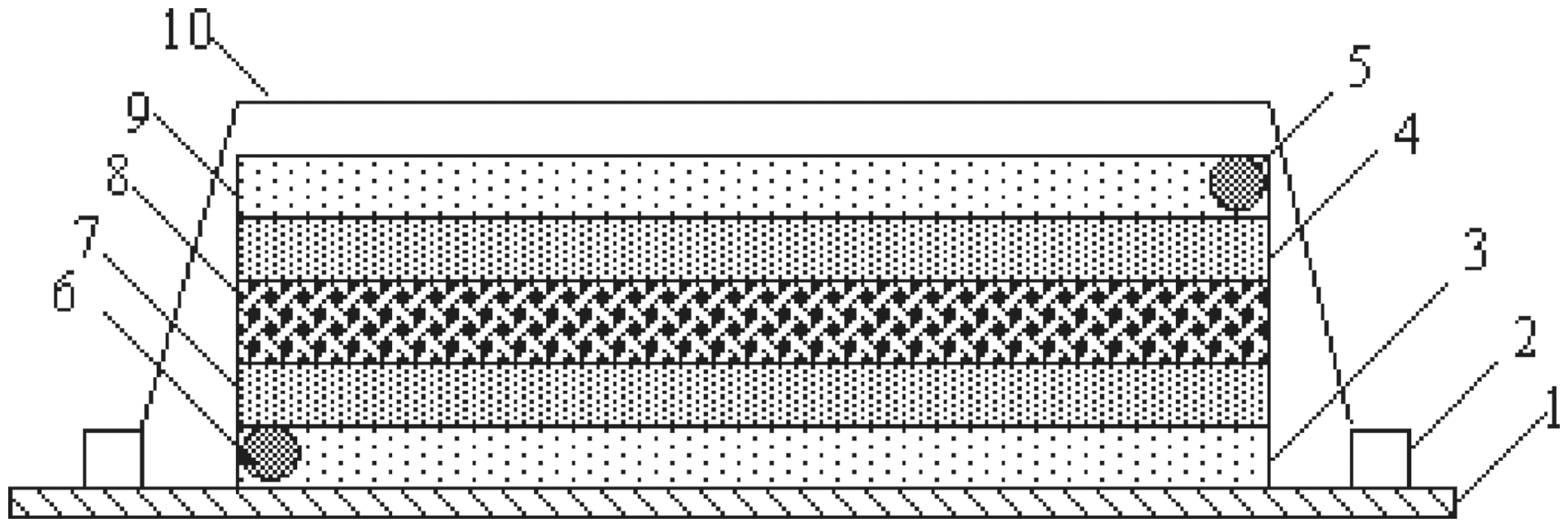
Mechanical properties of nanofilled epoxy resin
Tensile properties
To identify the effect of varying amounts of CNFs on bulk nanofilled matrix properties, the weight fraction of CNFs in epoxy was varied from 0 to 3 wt%. Tensile tests on neat and nanofilled epoxy were performed on a MTS-810 machine according to ASTM standard D638-89. The tensile strain rates considered were 0.02 min−1, 0.2 min−1, and 2 min−1. Five specimens were tested for each material configuration and strain rate combination, and the average tensile modulus, ultimate strength, and ultimate strain obtained from these tests are listed in Table 1. Tensile stress–strain curves for neat epoxy and CNF-filled epoxy at different strain rates are shown in Figure 3(a)–(d). All specimens failed immediately after the tensile stress reached the maximum value. However, the stress–strain curves showed considerable non-linearity before reaching the maximum stress, but no obvious yield point was found in the curves. Figure 3 also shows the effect of strain rate on the stress–strain curves of neat and CNF-filled epoxy. Both the moduli and ultimate tensile strengths increased with increasing strain rate, but the failure strain decreased with increasing strain rate.
Stress–strain curves for neat and carbon nanofibers (CNF)-modified epoxy at different strain rates: (a) neat epoxy, (b) 1 wt% CNF/epoxy, (c) 2 wt% CNF/epoxy, and (d) 3 wt% CNF/epoxy. Tensile properties of neat epoxy and carbon nanofibers (CNF)-modified epoxy.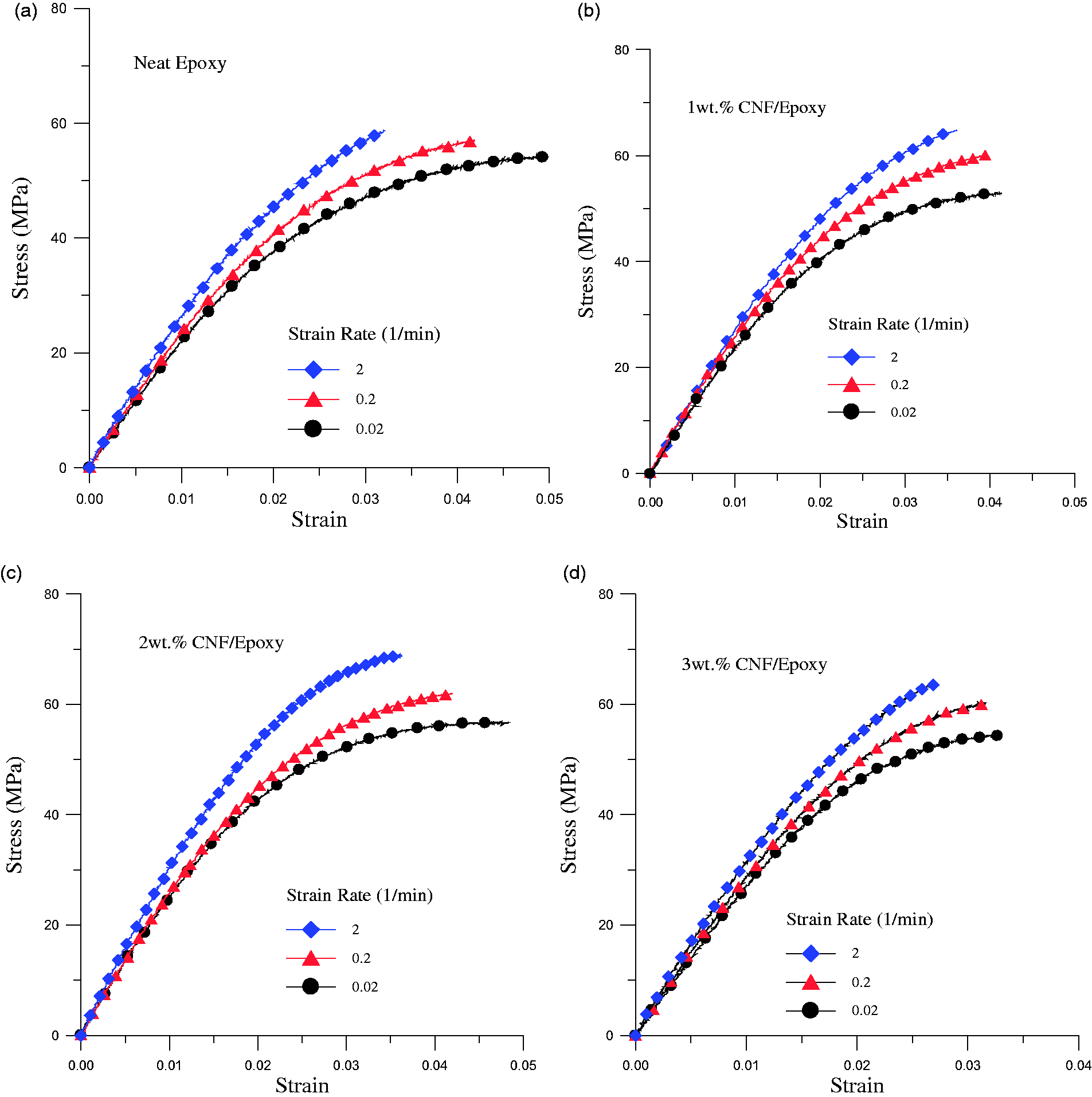
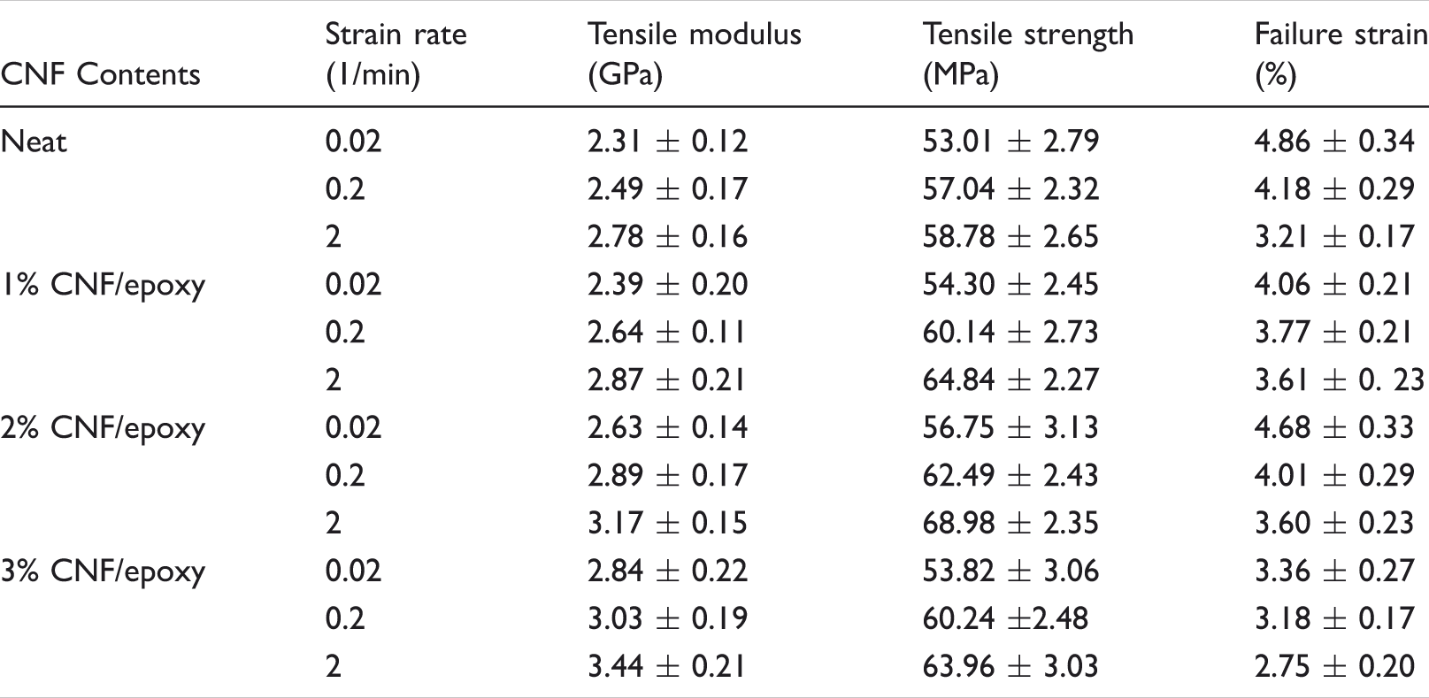
Figure 4 shows a comparison of the tensile stress–strain curves for the nanocomposites at the same strain rate (2 min−1). The tensile modulus of the nanofilled epoxy increases continuously with increasing CNF content. An improvement of about 19.4% in tensile modulus was observed with an addition of 3 wt% of CNF. However, Table 1 and Figure 4 also show that the system with 2 wt% CNFs led to the greatest enhancement in tensile strength (17.4%). While the nanocomposite tensile modulus increased continuously with increasing amounts of CNFs, the ultimate tensile strength began to degrade once the CNF loading exceeded 2 wt% (Figure 5).
Effect of carbon nanofibers (CNF) weight fraction on stress–strain curves of CNF/epoxy nanocomposites (strain rate = 2 min−1). Effect of carbon nanofibers (CNF) content on tensile modulus and tensile strength of epoxy.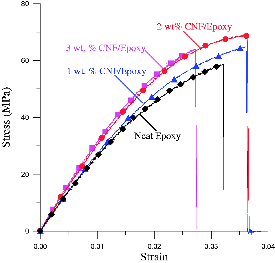
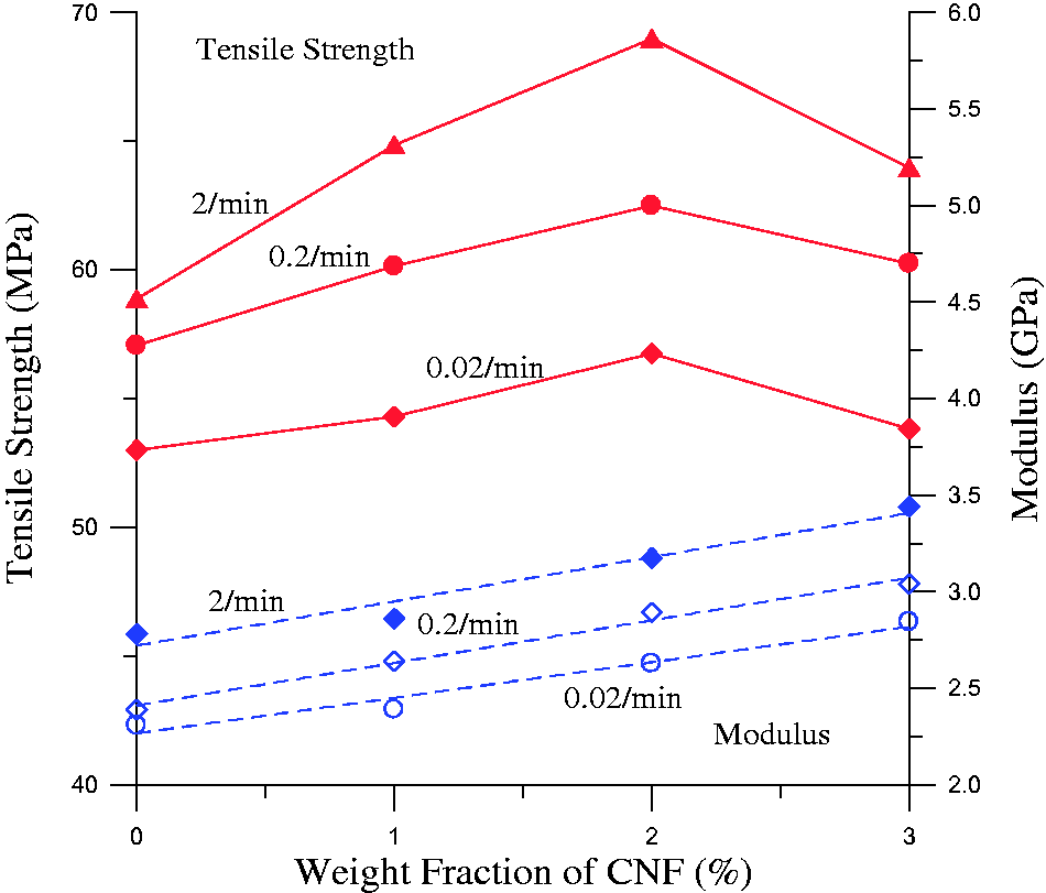
From Figure 3 and Table 1, it is obvious that neat and CNF-filled epoxy are strain rate-sensitive materials. Figure 6(a) and (b) shows the variation of tensile modulus (E) and tensile strength (σb) to be linear functions of the natural log of the strain rate ( Effect of strain rate on the (a) tensile modulus and (b) the ultimate tensile strength of neat epoxy and carbon nanofibers (CNF)-modified epoxy.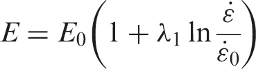

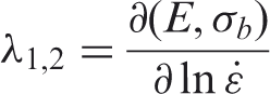
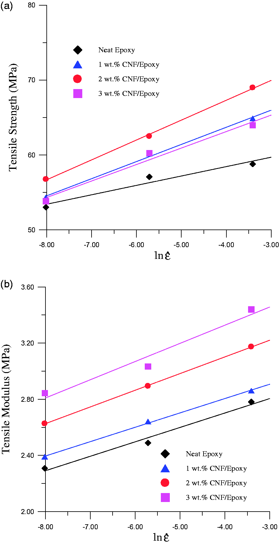
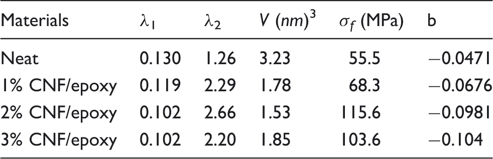
Constitutive parameters for neat epoxy and carbon nanofibers (CNF)-modified epoxy.
Fatigue performance
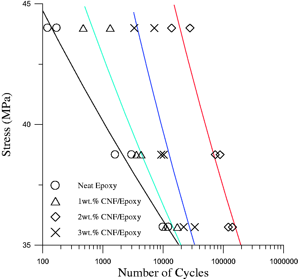
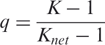
Load-controlled tension-tension fatigue tests were performed on the same MTS-810 machine at 21.5°C. The ratio of the minimum cyclic stress and the maximum cyclic stress was R = 0.1. A cyclic frequency of 1 Hz was used to reduce the possibility of thermal failure. Figure 7 shows the S-N fatigue life curves for the neat and nanofilled epoxy at ambient temperature. In this figure, the ordinate corresponds to maximum cyclic stress (S′) and the abscissa corresponds to the number of cycles to failure (N). At the same cyclic stress level, the fatigue life of the nanofilled epoxy was significantly higher than that for the neat epoxy. Based on standard arguments, the experimental S-N curves may be characterized by the following relationship,
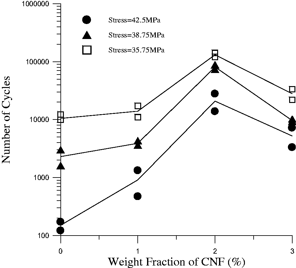
S-N curves for neat epoxy and carbon nanofibers (CNF)-modified epoxy. Effect of carbon nanofibers (CNF) weight fraction on the fatigue life of neat epoxy and CNF-modified epoxy for different cyclic stress levels.
Fracture toughness
Fracture toughness of neat and CNFs-filled epoxy were determined using single-edge notch tensile (SENT) specimens. Each SENT specimen was first cut by using diamond-coated wire and then cycled 100 times between 4% and 40% of the peak load at 1 Hz. During the SENT test, the change in specimen length, Δl, , was determined from the ram displacement of the MTS-810 machine.
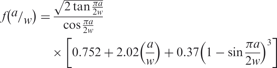
The critical stress intensity factor, Kc, was calculated according to the following equation:
23
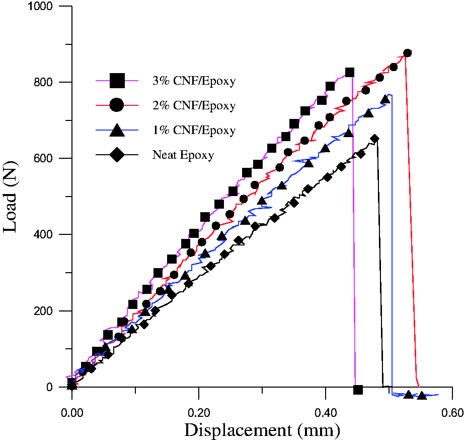
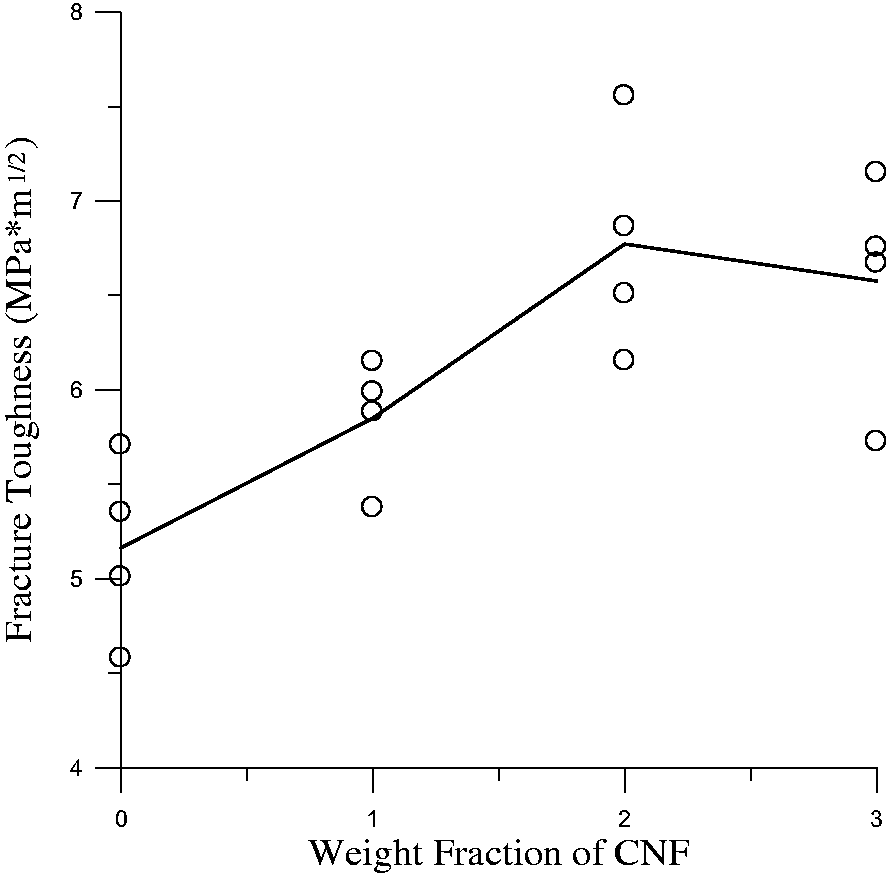
applied load on the specimen specimen thickness specimen width crack length Load-displacement curves from SENT testing of neat epoxy and carbon nanofibers (CNF)-modified epoxy. Effect of carbon nanofibers (CNF) weight fraction on the fracture toughness of neat epoxy and CNF-modified epoxy.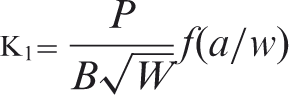
Fracture surface
To investigate the failure mechanisms in neat epoxy and nanofilled epoxy, the fracture surfaces of failed specimens were examined using SEM imaging. Figure 11(a) contains an SEM image of a typical fracture surface from a neat epoxy specimen; these specimens displayed classical cleavage-type fracture surfaces common to quasi-brittle materials with relatively low fracture toughness values. In contrast, Figure 11(b) contains a typical SEM image of the somewhat rougher fracture surface associated with a 2 wt% CNF/epoxy specimen. The increased surface roughness suggests that the presence of nanofibers resulted in a more tortuous crack growth path and an increase in fracture toughness. Figure 11(c) contains a higher magnification image of a fracture surface of a 2 wt% CNF/epoxy system that clearly shows the nanofibers were well separated and uniformly embedded in the epoxy resin; the pulled-out nanofibers evident in the figure suggest one potential toughening mechanism associated with the presence of CNFs as well as the possibility of a relatively weak CNF/epoxy interface. When the CNF content was increased to 3 wt%, the nanofibers became increasingly difficult to disperse in the epoxy matrix. As a consequence, cracks initiated due to the stress concentration occurring in the vicinity of large CNF agglomerates (Figure 11(d)). As shown in Figure 1, agglomerated CNFs were present prior to mixing with epoxy. At low CNF weight fractions, the ultrasonication processing was arguably able to deagglomerate the nanofibers; but when the CNF content was increased to 3 wt%, this process became more difficult. The high stress concentrations caused by the agglomerated particles did not affect the modulus, which is a volume averaged property, but reduced the strength by initiating local failures in the epoxy matrix. This mechanism explains the decrease in tensile strength, fatigue strength, and fracture toughness observed in 3 wt% CNF/epoxy specimens.
SEM images of (a) the fracture surface for neat epoxy; (b) the fracture surface for 2 wt% CNF-modified epoxy; (c) the dispersion of nanofibers and nanofiber pullouts in 2 wt% CNF-modified epoxy; and (d) agglomerated CNFs in 3 wt% CNF-modified epoxy.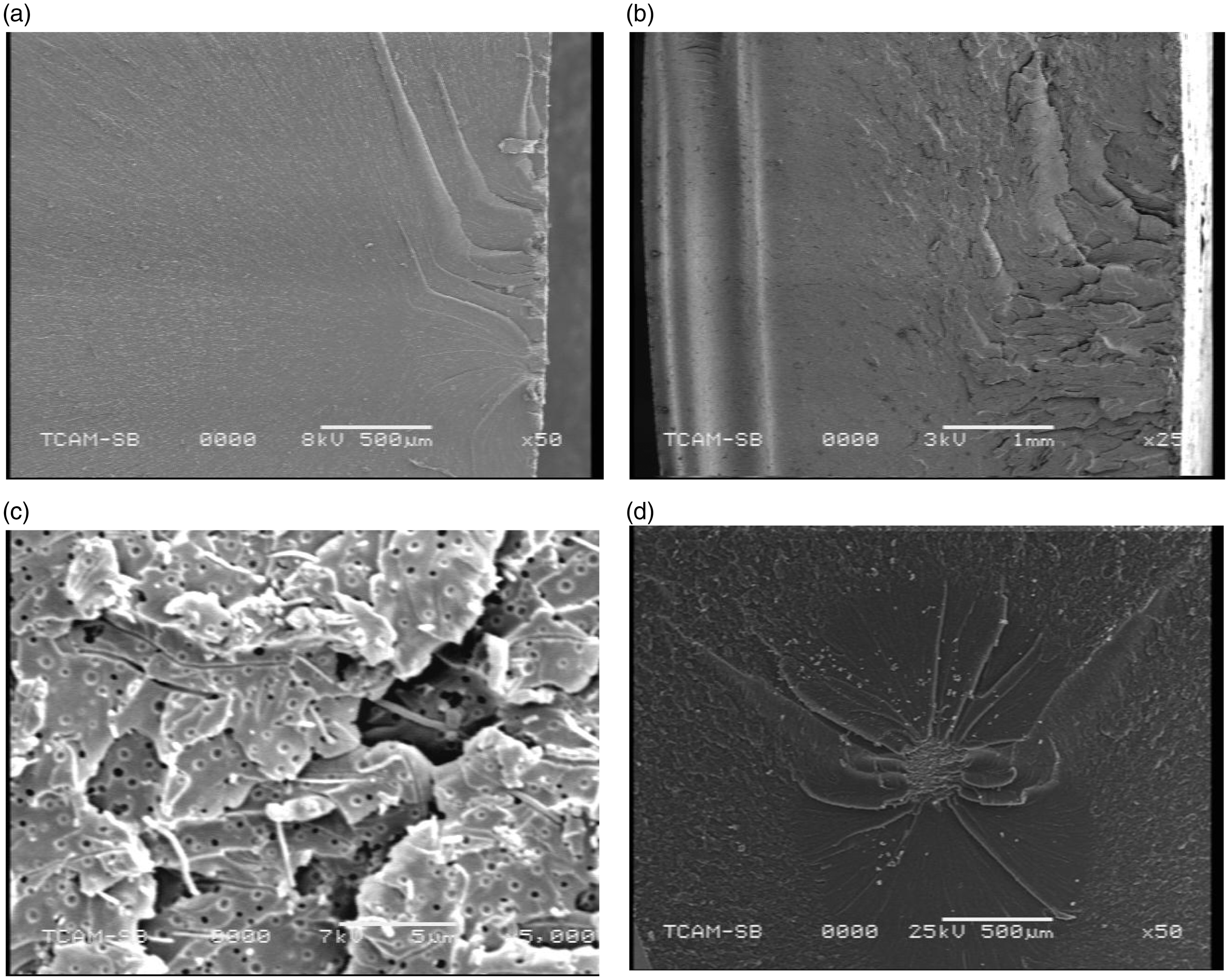
Mechanical properties of CF reinforced epoxy with and without CNF
Compression strength and open-hole compression strength
Based on the tensile, fatigue, and fracture test results of neat and CNF-reinforced epoxy, hybrid composite panels were manufactured by using satin weave CF in combination with either neat epoxy or 2 wt% CNF-modified epoxy. Room temperature compression and open-hole compression tests were performed to evaluate the matrix-dominated composite properties. Five compression samples were machined from each panel according to ASTM D3410 (specimen width, 10.0 mm; length, 114 mm). Four doublers (width, 12.4 mm; length, 51 mm) were bonded on the samples to prevent buckling (cf., Figure 12). The unreinforced gage length of the compression samples was 12 mm. To understand the effect of CNFs on the notch sensitivity of each material, a 3.2 mm diameter hole was drilled in center of the open hole specimens to generate a stress concentration factor kt = 2.4.
Specimens for compression and open-hole compression tests. (a) Front view. (b) Side view.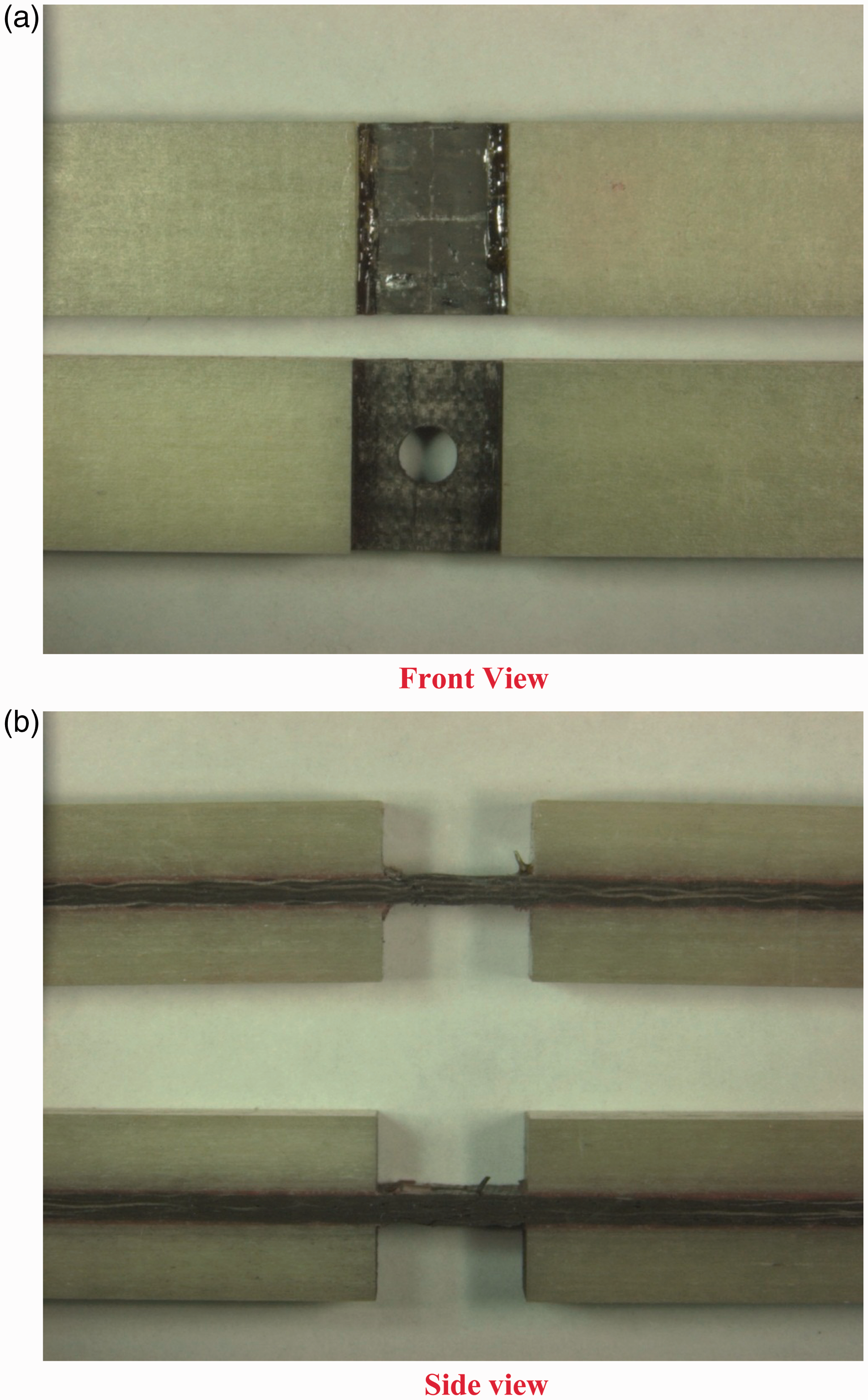
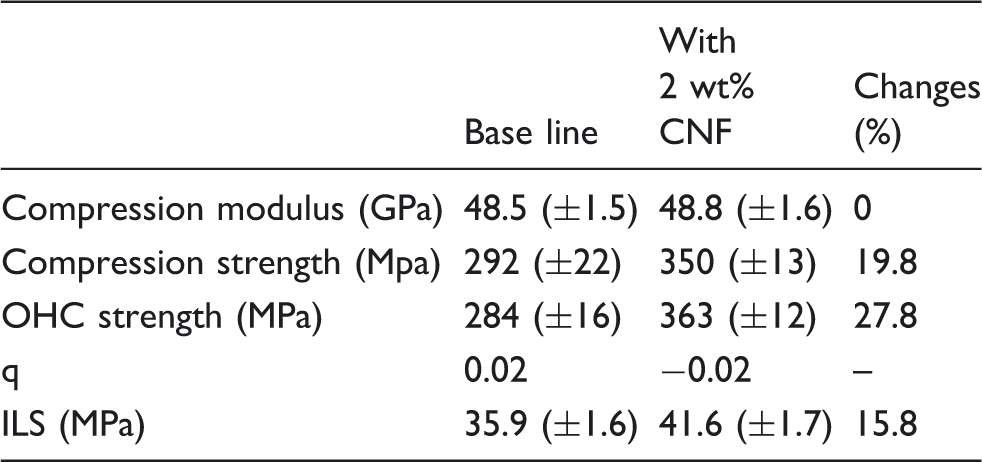
Typical compression stress versus displacement curves for the solid and open-hole composite specimens are shown in Figure 13. The CFRP specimens displayed linearly elastic behavior until sample failure. The specimens failed rapidly after reaching the maximum stress, with audible acoustic emissions as individual filaments fractured and/or the plies delaminated. By infusing 2 wt% CNFs in the epoxy matrix, the solid laminate compressive strength and failure strain were significantly improved. The hybrid composite specimens fabricated with CNFs showed a 19.8% increase in compressive strength and a 21% increase in failure strain relative to solid laminates fabricated using neat epoxy, with no appreciable change in compressive modulus. Similar results were obtained using open-hole compression specimens. For these specimens, however, the net stress was plotted as a function of displacement in Figure 13. Open-hole hybrid composite specimens infused with a 2 wt% CNF/epoxy resin displayed a 27.8% improvement in net compressive strength in comparison with composites infused with neat epoxy.
Compressive stress versus displacement curves for baseline CF/epoxy composites and CF/2 wt% carbon nanofibers (CNF)/epoxy hybrid composites with and without an open hole.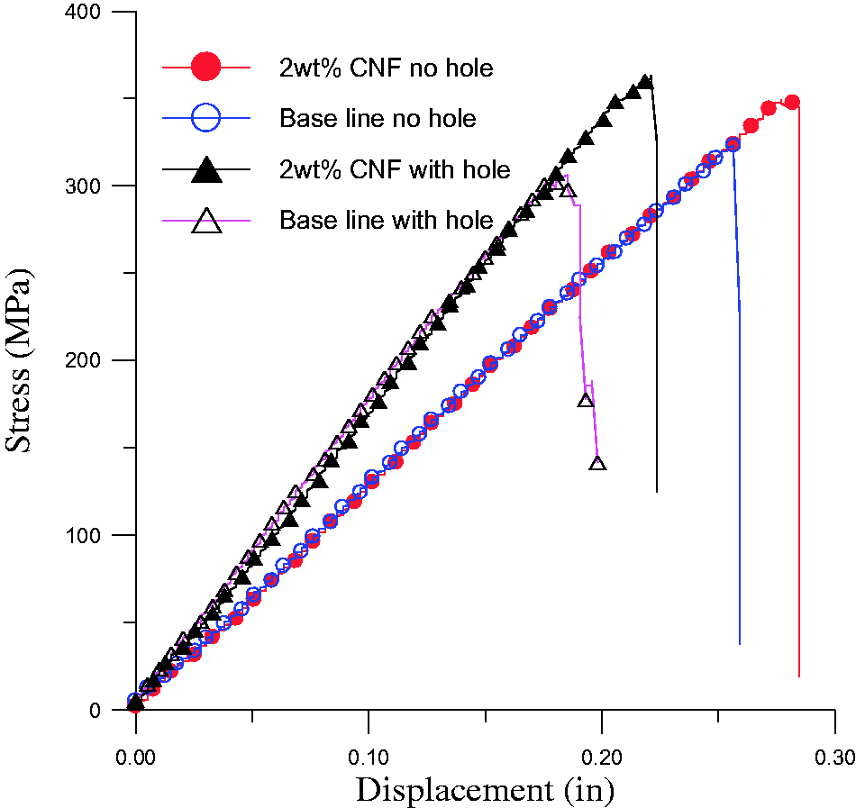


Matrix-dominated properties for carbon fibers (CF)/epoxy composites and CF/2 wt% carbon nanofibers (CNF)/epoxy hybrid composites.
Interlaminar shear strength
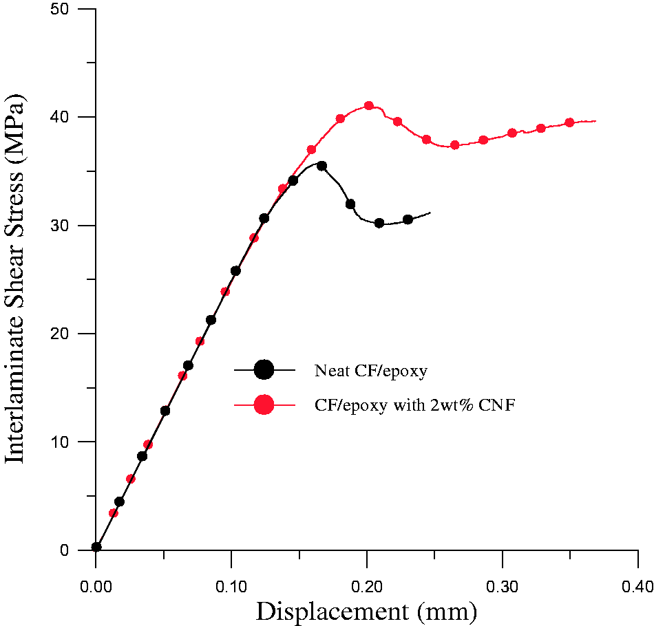
The interlaminar shear strength (ILSS) for CFRP composites prepared using satin weave carbon fabric infused with either neat epoxy or 2 wt% CNF-modified epoxy was determined. Short beam shear tests were performed on specimens with a span length of 12 mm per ASTM D2344. A transverse load was applied at the center of a given specimen until the first failure was observed. The peak load at first failure was then used to calculate the ILSS
Interlaminar shear stress from short beam shear testing of baseline carbon fibers (CF)/epoxy composites and CF/2 wt% carbon nanofibers (CNF)/epoxy hybrid composites.
Tensile and fatigue test
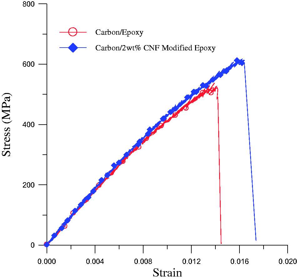
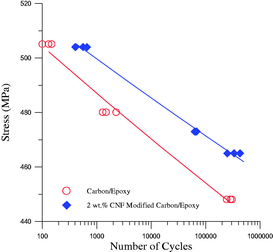
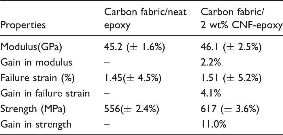
Tensile and fatigue tests according to ASTM D638 for composites fabricated with neat and 2 wt% CNF-modified epoxy (total specimen length, 120 mm; gage length, 50 mm; gage width, 12.7 mm). Typical quasi-static tensile stress–strain responses from these experiments are shown in Figure 15. Composites infused with 2 wt% CNF/epoxy resin resulted in an 11% enhancement in ultimate tensile strength (UTS) and a 4.1% enhancement in failure strain relative to composites prepared using neat epoxy; the composite axial modulus, however, remained relatively unchanged (Table 4). A series of stress-controlled tension–tension fatigue tests were performed at 21.5℃ at a stress ratio R = 0.1 and a cyclic frequency of 2 Hz. Figure 16 shows the measured S-N curves for CFRP composites prepared with and without CNFs. Inclusion of CNF-modified epoxy led to a significant improvement in fatigue life for all cyclic stress levels. Based on the experimental data, the idealized S-N curve for each composite may be approximated as
Tensile stress–strain curves for CF/epoxy composites and CF/2 wt% carbon nanofibers (CNF)/epoxy hybrid composites. S-N curves for CF/epoxy composites and CF/2 wt% carbon nanofibers (CNF)/epoxy hybrid composites. Tensile properties for carbon nano (CF)/epoxy composites and CF/2 wt% carbon nanofibers (CNF)/epoxy hybrid composites.
Fracture surface observations
SEM imaging was used to assess the differences in the fracture (delamination) surfaces associated with CF/epoxy composites and CF/2 wt% CNF/epoxy hybrid composites. For example, Figure 17(a) contains an SEM image of CFs in the vicinity of a delaminated surface in a CF/epoxy composite. The relatively smooth CF surfaces suggest that poor interfacial adhesion led to fiber/matrix decohesion during fracture. Figure 17(b) contains a corresponding SEM image of the epoxy matrix near the delamination surface. Smooth troughs are clearly visible where the CFs separated from the surrounding matrix. As an aside, the void-like pits appearing between fibers troughs in Figure 17(b) are due to second-phase rubber tougheners contained in the SC-15 epoxy. In contrast, the addition of CNFs to the matrix phase increased the tortuosity in the fracture surfaces and led to an increase in hybrid composite fracture toughness. Figure 17(c) contains an SEM image of CNF-modified matrix in the vicinity of the fracture surface from a CF/2 wt% CNT/epoxy composite. Note that the fiber troughs are fairly rough in appearance and that significant portions of the CNF-modified epoxy matrix remained adhered to the continuous fibers after fracture. This difference in the fracture (delamination) surfaces suggests that the addition of CNFs to the matrix improves adhesion between the matrix and continuous CFs due to the complex interactions between the constituent phases. Figure 17(d) contains a high-magnification SEM image of the fracture surface from a CF/2 wt% CNF/epoxy composite. Well-dispersed CNFs are clearly visible protruding from the fracture surface. CNFs may serve to bridge small matrix cracks and alter the trajectory of crack growth. CNF pullouts may provide a toughening mechanism that delays the initiation and growth of shear-dominated matrix cracks. During the shear crack propagation process, crack bridging inhibits crack opening and/or can result in a change in the crack growth path, resulting in increased matrix-dominated strength.
25
Fracture surface of composite. (a) neat CF/Epoxy, (b) matrix neat CF/Epoxy, (c) 2 wt% CNF-modified CF/epoxy and (d) 2wt% CNF-modified CF/epoxy.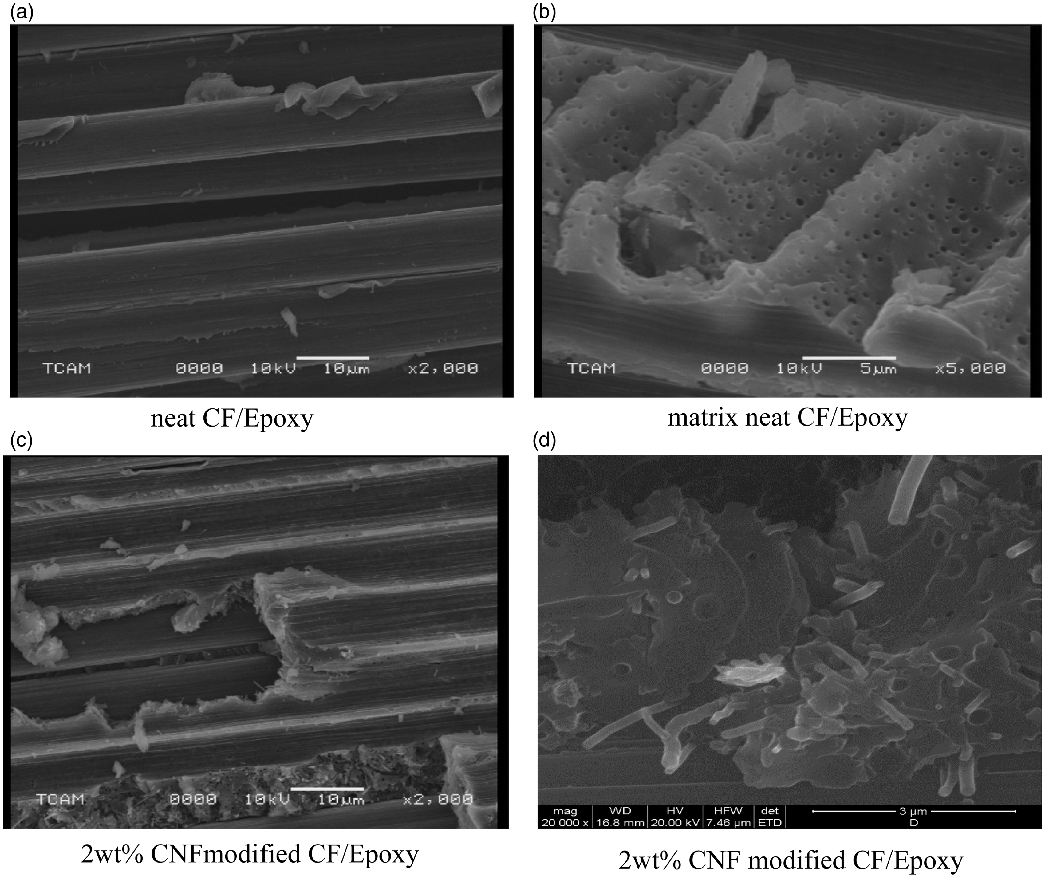
Conclusions
In this investigation, a series of mechanical property characterization tests were performed on satin weave carbon/epoxy composites, in which SC-15 epoxy resin was modified with 2 wt% PR-24PS vapor-grown CNFs prior to infusion into the continuous CF preform.
Quasi-static and low-strain rate tension tests, tension-tension fatigue tests, and fracture tests were performed on 0–3 wt% CNF-reinforced epoxy specimens in order to determine the weight fraction of CNFs leading to the optimal mechanical properties of the modified epoxy matrix. In general, the tensile modulus of the modified epoxy increased with increasing amounts of CNFs. The strength-related properties (ultimate tensile strength, fatigue life, fracture toughness) also increased significantly with increasing amounts of CNFs and reached maximal values at an optimal CNF weight fraction of 2 wt%. Moreover, the enhancement in tensile properties of CNF-modified epoxy became more pronounced for specimens loaded at higher strain rates. Further increases in nanofiber content, however, resulted in a degradation in nanocomposite strength and fatigue life; this degradation is likely due to local stress concentrations associated with nanofiber agglomerates or otherwise poorly dispersed CNFs.
Vacuum assisted resin infusion molding was used to fabricate unidirectional hybrid composite panels comprised of satin weave carbon fabric and epoxy resin modified with 2 wt% CNFs. Quasi-static uniaxial compression tests, quasi-static open-hole compression tests, and short beam shear tests were performed to assess the effect of CNFs on matrix-dominated composite properties. Hybrid composites containing 2 wt% of CNFs in the epoxy matrix resulted in compressive strength, open-hole compressive strength, and ILSS values that were 19.8%, 27.8%, and 15.8% greater, respectively, than those for woven fabric composites prepared with neat epoxy (i.e. no CNFs). Quasi-static uniaxial tension tests and tension–tension fatigue tests of CF/2 wt% CNF/epoxy hybrid composites also led to similar improvements in the composite ultimate tensile strength and fatigue life relative to composites infused with neat epoxy. SEM images of hybrid composite micro-fracture surfaces indicated that randomly distributed CNFs provide some crack bridging, reduce crack opening, and result in crack turning for small cracks. Such mechanisms are the likely reason for the improvement in mechanical properties. These results suggest that small amounts of nanoreinforcements may be effectively used to tailor/optimize the properties of traditional continuous fiber-reinforced composites.
Footnotes
Acknowledgements
The authors gratefully acknowledge the support of National Science Foundation.