
Abstract
The objective of this study was to investigate the effects of core material and its thickness on impact behavior of sandwich composite plates subjected to low-velocity impact, experimentally. Poly(vinyl chloride) (PVC) and poly(ethylene terephthalate) (PET) foams were selected as the core material, having approximate density of 65 kg/m3 and 60 kg/m3, respectively, and thicknesses of 5, 10, and 15 mm. The stacking sequence of the sandwich composites is
Introduction
Sandwich composite structures have been widely used in numerous application fields such as aerospace, marine, automotive, windmill, and sports industries and have specific advantages like high-bending stiffness, low weight, excellent thermal insulation, acoustic damping, and ease of repairs when compared to other conventional laminated composites. In spite of having these advantages, sandwich composite structures are sensitive to impact loading and may be subjected to various impacts such as tool drops, bird strikes, hail storms, and runway debris during the service life. These impacts cause reduction in the strength of the structures.
To ensure the reliability and safety of sandwich composite structures, impact behavior of sandwich composite structures is intensively studied by many researchers for a long time. Studies on this field can be divided into the two main categories as core material and thickness of core material effects on impact behavior of sandwich composites. Some of the relevant previous studies are presented below.
Impact behavior of sandwich structures is mainly affected by core materials and their thicknesses. It is seen that the energy-absorbed capacity of sandwich composites increases with increasing core thickness. 1 The impact damage was utilized in the foam and honeycomb cores by using destructive and non-destructive test methods. Impact response of sandwich composite panels with poly(vinyl chloride) (PVC) foam core and balsa wood core was studied by Atas and Sevim. 2 They performed a number of tests under various impact energies. To analyze the damage process of the sandwich composites, they obtained load-deflection curves and energy-profile diagrams. They observed damage modes including fiber fractures at upper and lower skins, delamination between glass-epoxy layers, core shear fractures, and face/core debonding. Anderson and Madenci 3 investigated the low-velocity impact response of sandwich composites, experimentally. They used a variety of sandwich configurations with graphite/epoxy face sheets and foam or honeycomb cores. Dear et al. 4 studied the impact toughness of different lightweight sandwich panels and composite sheet materials. They prepared the specimens from sheet-molding compound, glass-mat thermoplastic, and honeycomb-sandwich panels employing different skin and core materials. Hazizan and Cantwell 5 studied the low-velocity impact response of 11 sandwich structures based on low-density polymeric foams. They obtained different failure modes and observed that the dynamic response of sandwich structures depends on elastic properties of the foam core material. Xiong et al. 6 performed quasi-static uniform compression tests and concentrated on low-velocity impact tests to reveal the failure mechanisms and energy-absorption capacity of two-layer carbon-fiber composite sandwich panels with pyramidal truss cores. They fabricated three different volume-fraction cores having different relative densities. They obtained the failure modes and deformation mechanisms of carbon-fiber sandwich composite and compared with glass fiber-woven textile truss cores. Impact, compression after impact (CAI), tensile stiffness properties of carbon fiber, and Kevlar combination sandwich composites were investigated by Gustin et al. 7 The impact-side face sheets consisted of different combinations of carbon fiber/Kevlar and carbon fiber/hybrid while the bottom face sheets remained entirely carbon fiber. They have obtained information about absorbed energy and maximum impact force. Herup and Palazotto 8 performed low-velocity impact and static-indentation tests on sandwich plates composed of 4 to 48 ply graphite/epoxy cross-ply laminate face sheets and Nomex honeycomb cores to characterize damage initiation as a function of face sheet thickness and loading rate. The effect of integrated sandwich structure with an orthogrid stiffened syntactic foam core on impact characterization was investigated by Li and Muthyala. 9 To evaluate the impact response, they performed the low-velocity impact tests and CAI tests. C-scan and SEM observations were implemented to investigate the impact damage. They have observed that the integrated core enhanced the impact energy transfer and energy absorption. Hosur et al. 10 investigated the foam-filled 3-D integrated core sandwich composite laminates with and without additional face sheets. For additional facing, they used plain-weave S2-glass and twill-weave carbon fabrics on top and bottom sides of the panels in four different monolithic combinations. They evaluated and compared the peak load, deflection, and absorbed energy for different types of laminates and studied the failure modes by sectioning the samples and observing under optical microscope. Bhuiyan et al. 11 evaluated the low-velocity impact behavior of sandwich panels, which consist of different types of core (neat and nanophased) and biaxial-braided carbon fiber/epoxy face sheets. They have observed that nanophased foams have smaller damage area than neat counterparts. Also, nanophased foams have higher peak loads compared with the neat foam sandwich. Salehi-Khojin et al. 12 presented the impact response of sandwich composites with Kevlar/hybrid and carbon face sheets subjected to different temperatures. Specimens were tested at a temperature range of −50℃ – 120℃ and were subjected to low-velocity impact energies of 15 J, 25 J, and 45 J. It is seen that impact performance of these sandwich composites changes over the range of temperature, significantly. Schubel et al. 13 investigated the low-velocity impact behavior of sandwich panels consisting of woven carbon/epoxy and a PVC foam core. Samples were impacted with a drop mass setup, and the load, strain, and deflection values were obtained. They characterized and quantified the damage area after the tests. Experimental results were compared with analytical and finite element model analysis and found to be in good agreement. 13
Park et al. 14 investigated the damage resistance of sandwich structure. The Nomex® honeycomb core was selected as a core material, having thicknesses of 10 mm and 20 mm, and two kinds of face sheets (carbon/epoxy and glass/epoxy laminates) were used and samples were exposed to low-velocity impact. Results show that their impact response was greatly influenced by core thickness, and the effect of core thickness varied with the face-sheet materials. Mohan et al. 15 investigated the impact responses of aluminum foams with various tailored face sheets and foam thicknesses. They carried out the experiment by using hemispherical indenters on blocks of aluminum foam with and without the face sheet. Their results show that increase in thickness of foam and the use of face sheet enhance the impact energy-absorption capacity. Sawal and Akil 16 performed low-velocity impact tests on sandwich panels composed of aluminum face sheets and thermoplastic honeycomb cores to characterize the impact performance as a function of core thickness and drop heights. They evaluated and compared impact parameters such as maximum impact force, impact energy, and impact damage area. They found that panels with thicker core exhibited higher impact force than thinner core counterparts. Impact response of integrated sandwich core composites was carried out by Vaidya et al. 17 They considered three thicknesses of integrated and functionality-embedded E-glass/epoxy sandwich core including 6, 9, and 17 mm. They have observed that the functionality-embedded cores provided enhanced low-velocity impact resistance due to additional energy-absorption mechanisms.
Karakuzu et al. 18 have investigated the effects of impact energy, impactor mass, and impact velocity on the maximum contact force, maximum deflection, contact time, absorbed energy, and overall damage area of glass/epoxy-laminated composites, experimentally and numerically. It is seen that the numerical results are in good agreement with the experimental results. Aslan et al. 19 have studied the size effects including both in-plane-dimensional and thickness effects for laminated woven E-glass-epoxy composite subjected to low-velocity heavy mass impact. The studies have been carried out with plate dimensions of 150 × 150 mm, 150 × 100 mm, and 150 × 50 mm for in-plane-dimensional effect. Two nominal thicknesses with averages of 1.4 and 2.8 mm are used for studying the thickness effect. The contact forces between the impactor and the composite plate as functions of time, transient stresses during impact, and the predicted delamination sizes of composites are found numerically.
It is seen from the literature survey that most of the researchers have focused on the impact characteristics of the sandwich composites only in the selected core thickness. Also, both PVC and PET foam cores as a core material and thickness effect are little studied. The primary objective of this paper is to investigate the effects of core material, and its thickness on the impact behavior of sandwich composites subjected to low-velocity impact, experimentally. In this context, damage process of sandwich composites has been examined with related graphs. Damage modes of the top and bottom surfaces of the samples were investigated by visual inspection. Also, the cross-sectional area of the impacted surface was examined with destructive methods by using an abrasive water-jet machine.
Fabrication of the specimens and impact testing
All sandwich and laminated composite specimens used in this study were manufactured using vacuum-assisted resin infusion-molding process (VARIM) in the Composite Research Laboratory of Dokuz Eylul University in Izmir. E-glass fabrics
Mechanical properties of the core materials.
CEAST 9350 with High-Energy System (Fractovis Plus) impact testing machine was used to conduct the low-velocity impact tests in the Composite Research Laboratory of Dokuz Eylul University. A broad range of applications requiring from low to high-impact energies can be performed with this machine. The impactor, which was used to strike the clamped specimens, is a hemispherical indenter with a 12.7 mm diameter and attaches to maximum loading capacity of 22.4-kN piezoelectric force transducer. The total falling mass of the impactor is 5 kg (included impactor and crosshead mass). There is an anti-rebounding system in the testing machine to prevent the repeated impacts on the specimen. The drop-weight testing machine generates up to 1800 J maximum potential energies via the additional mass, and this additional mass increases the speed of the impactor up to 24 m/s. A data-acquisition system, which allows acquiring 16,000 data throughout the tests, was used to perform the history of the impact event.
Results and discussion
Impact tests were conducted on at least five specimens for each experimental parameter increased from 10 J to 70 J impact energies and specimens with PET and PVC cores of 5 mm, 10 mm, and 15-mm core thicknesses and also composite plate manufactured without core material.
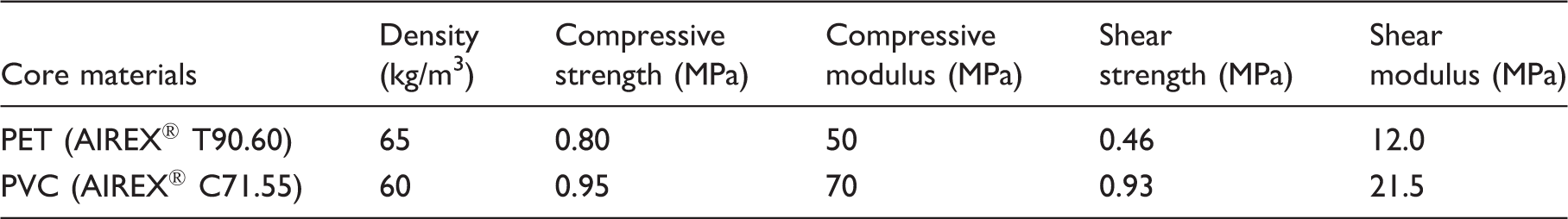
Contact force versus deflection histories of specimens manufactured without core material and with PET foam core, having 10-mm core thickness, impacted at 10 J, 15 J, 20 J, 25 J, 30 J, 35 J, 40 J, 50 J, and 70 J are given for an example in Figures 1 and 2, respectively. It is seen from Figure 1 that the deflection of the specimen increases with increasing impact energy level. Maximum contact forces do not change significantly with increasing the impact energy level after 20 J. Unloading portions of the contact force-deflection curves return in the parallel to loading portion of the curves in the rebounding cases (10 J, 15 J, and 20 J). In the penetration (25 J) and perforation (30 J, 35 J, 40 J, 50 J, and 70 J) cases, unloading portions of the curves do not return parallel to the loading portion of the curves. In the penetration cases, contact forces do not go toward to zero exactly because of the friction between impactor and specimen.
The contact force versus deflection histories of specimens without core material. The contact force versus deflection histories of specimens with PET foam core having 10-mm core thickness.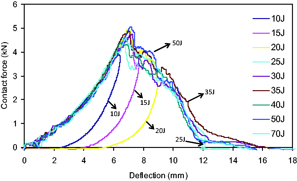
As can be seen from Figure 2, with increasing the impact energy level, deflections of the specimens increase. In the rebounding cases (10 J and 15 J), the curves have only one peak. This situation can be explained with the damages of only top face sheet. But, in the higher impact energy levels or penetration (20 J and 25 J) and perforation (30 J, 35 J, 40 J, 50 J, and 70 J) cases, the curves have two peaks as the top and bottom face sheets are damaged by the impactor, respectively.
Impact test results of specimens with PET and PVC foam cores
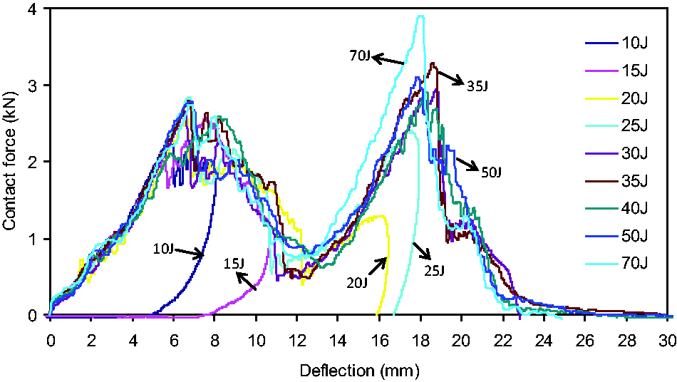
Contact force versus deflection diagrams of specimens with PET foam cores are given in Figure 3 for impact at 15 J, 25 J, 30 J, and 40 J critical energies and three different core thicknesses and specimens without core materials or with 0 mm core. From the result of this figure, it is seen that the contact force values decrease by increasing the core thickness in each energy level. And, maximum deflection values increase by increasing the core thickness in each energy level. The loading portion of the curves for all core thickness is nearly same. However, the unloading portion of the curve is different because of different damage mechanisms. A significant property of the sandwich composites is to increase the bending stiffness by increasing the moment of inertia. But, as can be seen from Figure 3, the bending stiffness of the specimens with 0-mm core thickness is higher than all the specimens with cores. This is related to the number of lamina, which is subjected to impactor. In other words, there are eight laminas in 0-mm core thickness specimens while there are only four laminas in the upper face sheet in specimens with cores. From the figure, impact response of upper face sheet, foam, and lower face sheet can be considered separately from each other. Therefore, bending stiffness in sandwich composites is decreased in spite of using core material. The contact force-deflection curve of specimens with PET foam core impacted at 15 J represents the rebounding case (Figure 3(a)). It is seen that only one peak occurs. This means impactor return from the top face sheet. In Figure 3(b), the failure starts in the bottom face sheet, and in Figure 3(c), impactor damages top and bottom face sheet, respectively, and stops in the specimens. This case is named as penetration. And, 30-J energy level is the initial of the penetration–perforation transition energy. In the case of perforation illustrated in Figure 3(d), it is seen that unloading portions of the curves do not return parallel to loading portions of the curves. This means impactor does not return from the specimen. From Figure 3(c) and (d), second peak value for 10 and 15-mm core thickness is greater than the first peak value. This situation may be explained with the deformation characteristics of the foam-core materials. The stiffness of the bottom face sheet during impact event increases by increasing the core thickness that leads to increase the second peak value. Also, specimens having 5-mm core thickness show the nearly same behavior with specimens without core material. Because the core thickness is selected small, the specimens behave as a whole. Namely, top and bottom face sheets and core material show the similar characteristic with laminated composite plate. And so, effect of core material on impact behavior of specimens is less than the other core thicknesses. For specimens with PVC foam of 10 mm thickness, results obtained are similar to the results obtained by Atas and Sevim.
2
Contact force versus deflection curves of the specimens with PET foam core impacted for various thickneses at (a) 15 J, b) 25 J, (c) 30 J, and (d) 40 J.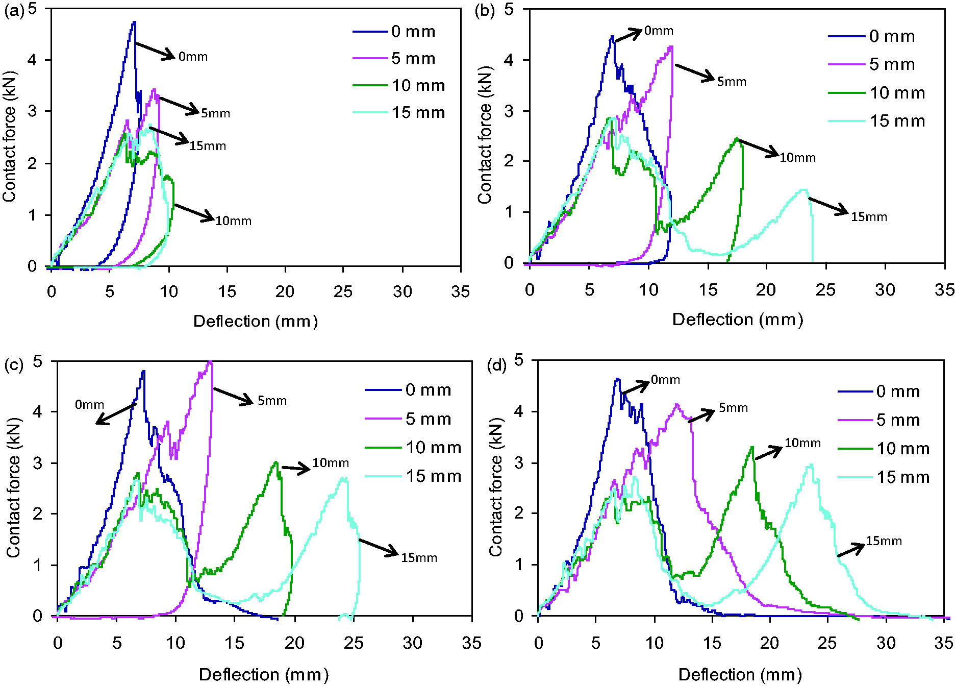
Contact force-deflection behaviors of specimens with PVC foam cores impacted at 15 J, 25 J, 30 J, and 40 J are similar to specimens with PET foam cores as shown in Figure 4. The bending stiffness of the specimen with 0 mm core is nearly same with that of with PVC core. Bending stiffness is maximum at the specimen with PVC foam core and minimum at the specimen with PET foam core. This property is compatible with the compressive modulus of the core materials (Table 1).
Contact force versus deflection curves of the specimens with PVC foam core impacted for various thicknesses at (a) 15 J, b) 25 J, (c) 30 J, and (d) 40 J.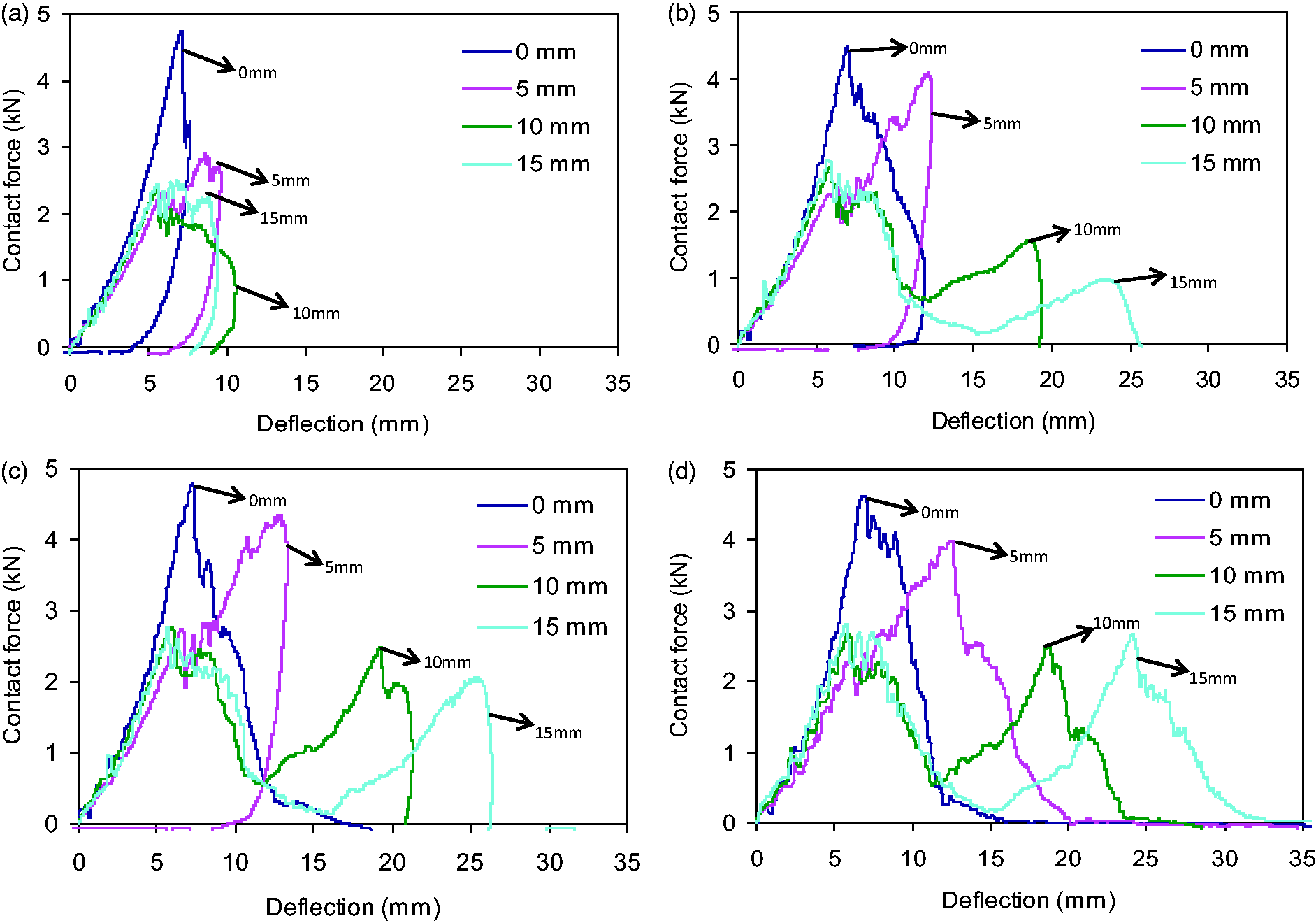
Figure 5 shows the maximum contact force-impact energy diagram of specimens with PET and PVC foam cores for three different core thicknesses and specimens without core materials. The value of maximum contact force decreases by increasing the core thickness (Figure 5(a)) except for specimens with PVC foam cores (Figure 5(b)). In the specimens with PVC foam cores, the value of maximum contact force in the 15-mm core thickness is greater than 10-mm core thickness. Specimens behave more rigid in the small thicknesses. And, specimens having 10 mm and 15-mm core thicknesses show nearly the same characteristics. Also, in the specimen with 5-mm core thickness, the value of maximum contact force increases rapidly until the peak value corresponds to the penetration level. After this value, the maximum contact force decreases by increasing energy, and it does not change significantly in higher energies, which correspond to the perforation level. With increasing the core thickness, variation of contact force value seems to be nearly the horizontal line in each core material.
Maximum contact force versus impact energy curves of specimens with (a) PET and (b) PVC foam cores for various thicknesses.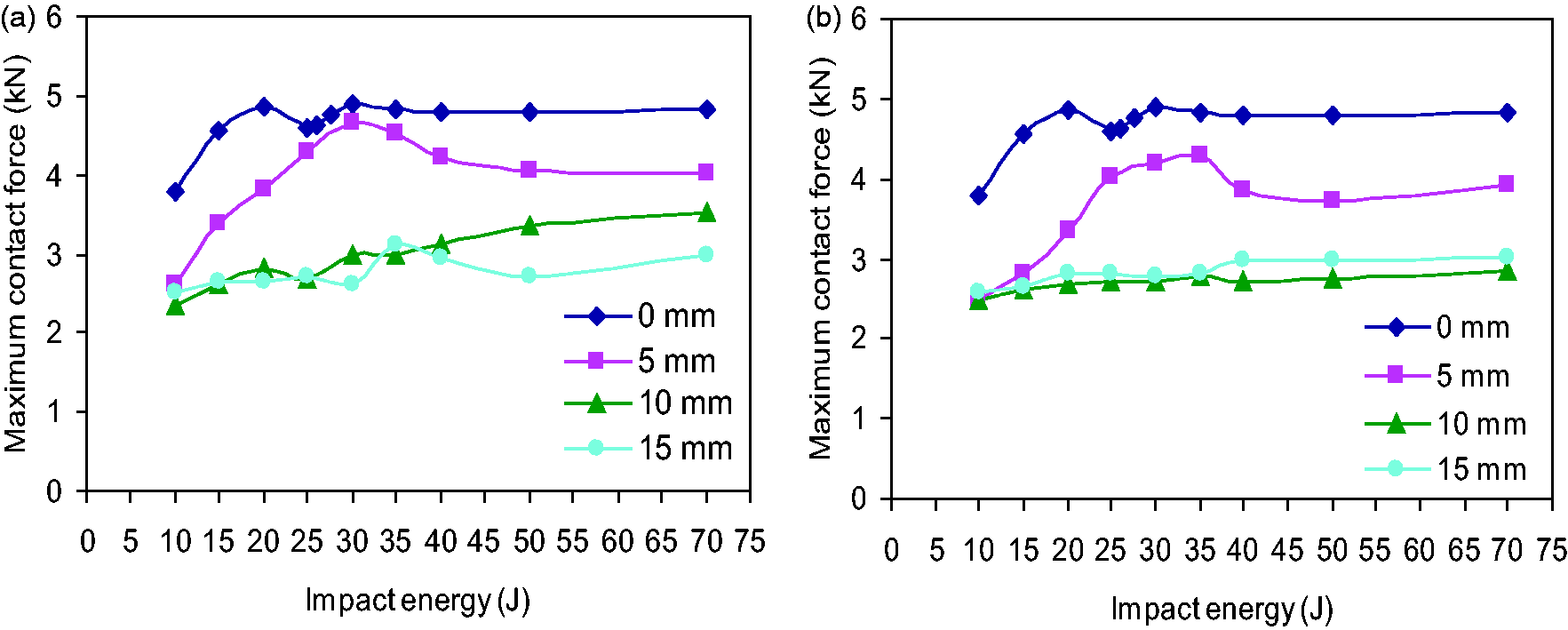
Contact time-impact energy histories of specimens with PET and PVC foam cores for three different core thickness and specimens without core materials are shown in Figure 6. Specimens with 5-mm core thickness and without core materials show similar characteristic. These curves have only one peak value that corresponds to the perforation threshold. But, for the curves of specimens having 10 mm and 15-mm core thicknesses, there are two peaks. First and second peaks are the perforation threshold of top and bottom face sheets, respectively. After the perforation threshold, contact time decreases suddenly and continues nearly linear. And, the contact time value increases by increasing the core thickness in each core material.
Contact time versus impact energy curves of specimens with (a) PET and (b) PVC foam cores for various thicknesses.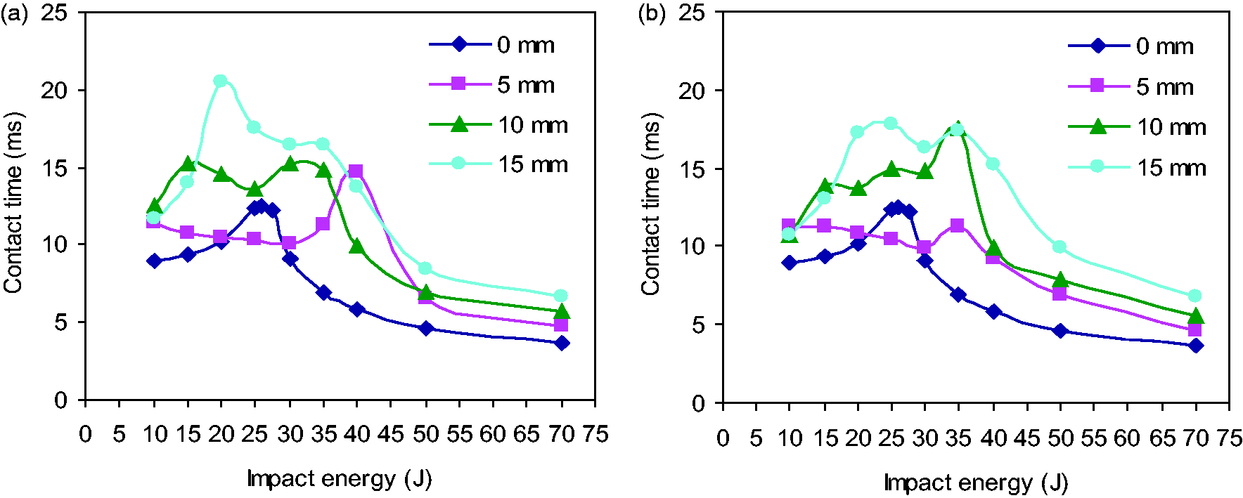
The maximum deflection-impact energy curves of specimens with PET and PVC foam cores for three different core thickness and specimens without core materials are given in Figure 7. Maximum deflection-impact energy behaviors of those specimens are similar to each other. Maximum deflection values increase by increasing the core thickness. The maximum deflection of specimens with PET foam core does not change significantly after 40 J energy level. Because this energy level follows the perforation threshold for specimens with PET foam cores.
Maximum deflection impact energy curves of specimens with (a) PET and (b) PVC foam cores for various thicknesses.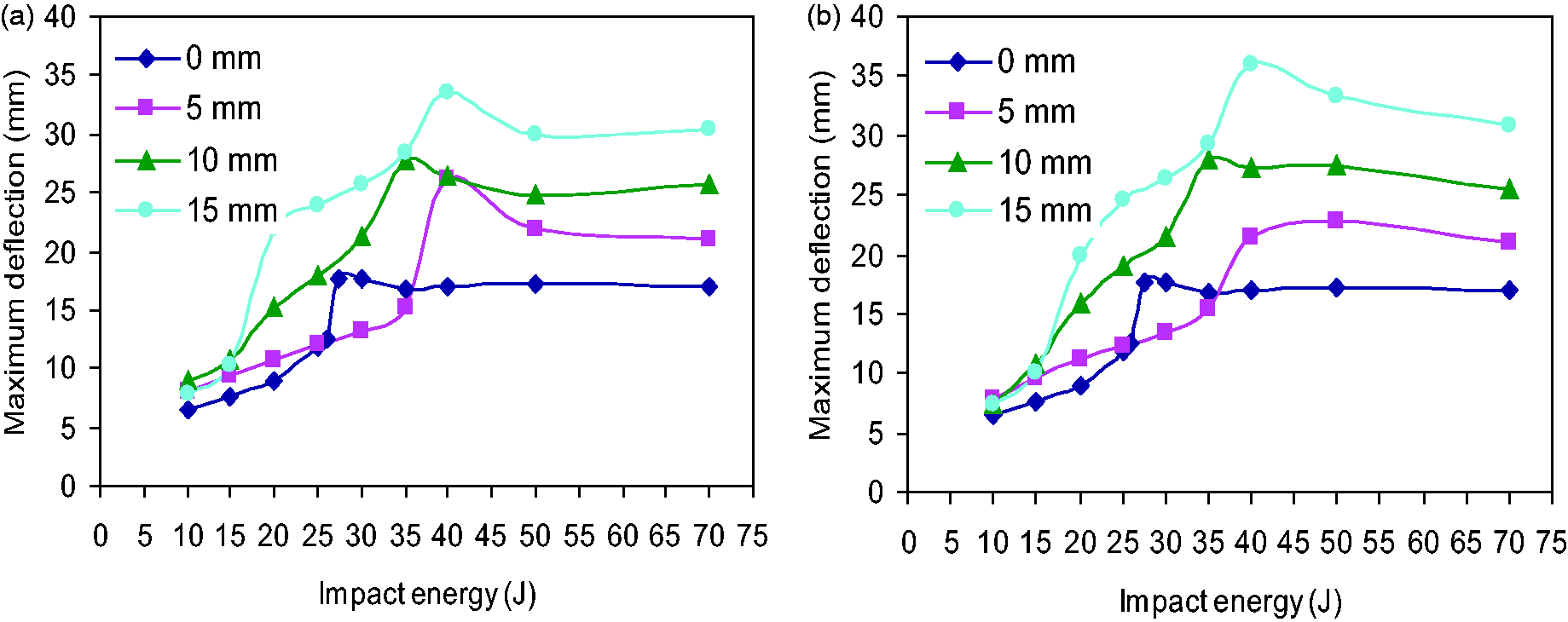
Figure 8 shows the energy-profile diagrams of specimens with PET and PVC foam cores. Behaviors of those specimens are similar to each other. It is seen from the figure that the excessive energy that causes rebound of impactor decreases by increasing the core thickness. In contrast, the absorbed energy increases. The first penetration level is obtained as 26 J, 35 J, 20 J, and 15 J for specimens with PET core thicknesses of 0 mm, 5 mm, 10 mm, and 15 mm, respectively, while it is 26 J, 35 J, 15 J, and 15 J for specimens with PVC core of same thicknesses. Also, penetration portion increases by increasing the core thickness. In the higher-core thickness, the penetration case starts 15 J and lasts until the perforation case. The perforation thresholds are 26 J, 40 J, 35 J, and 35 J for PET cores with 0 mm, 5 mm, 10 mm, and 15-mm core thicknesses, respectively, while they are 26 J, 35 J, 35 J, and 35 J for PVC cores with same thicknesses. After this impact energy level, the absorbed energy is nearly constant. For the specimens with PVC core of 5 mm thickness and specimens without core, penetration and perforation thresholds seem the same. This means penetration does not have exists, and only perforation occurs.
The energy profile diagram for specimens with (a) PET and (b) PVC foam cores for various thicknesses.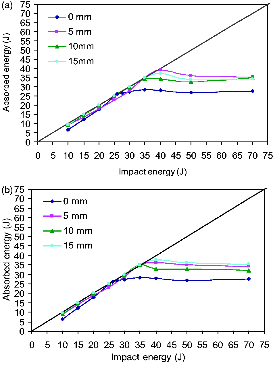
Damages of specimens
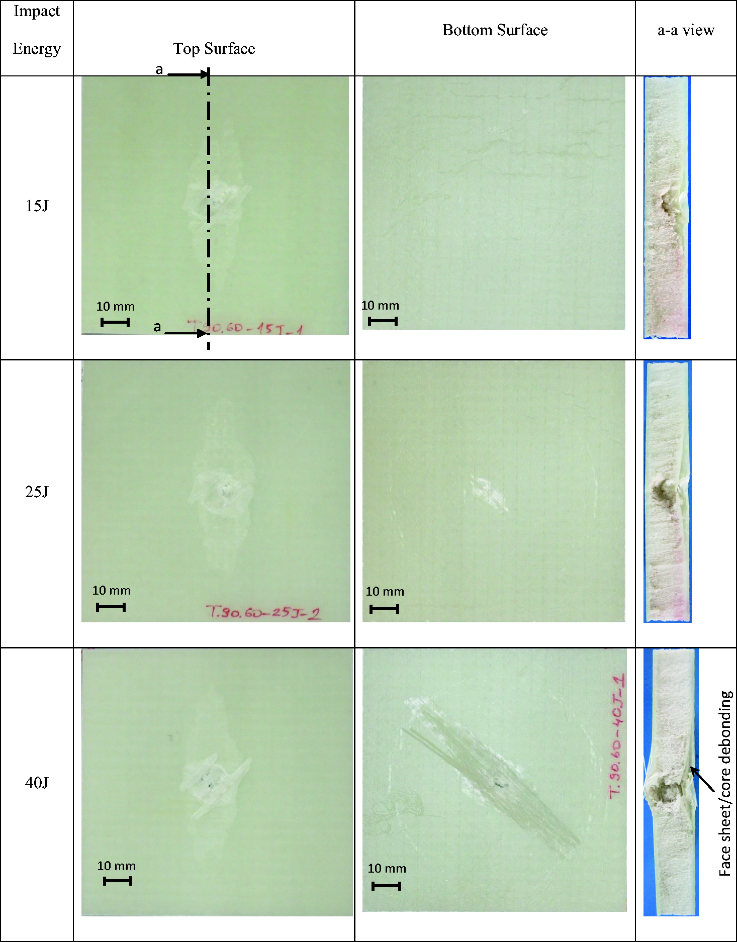
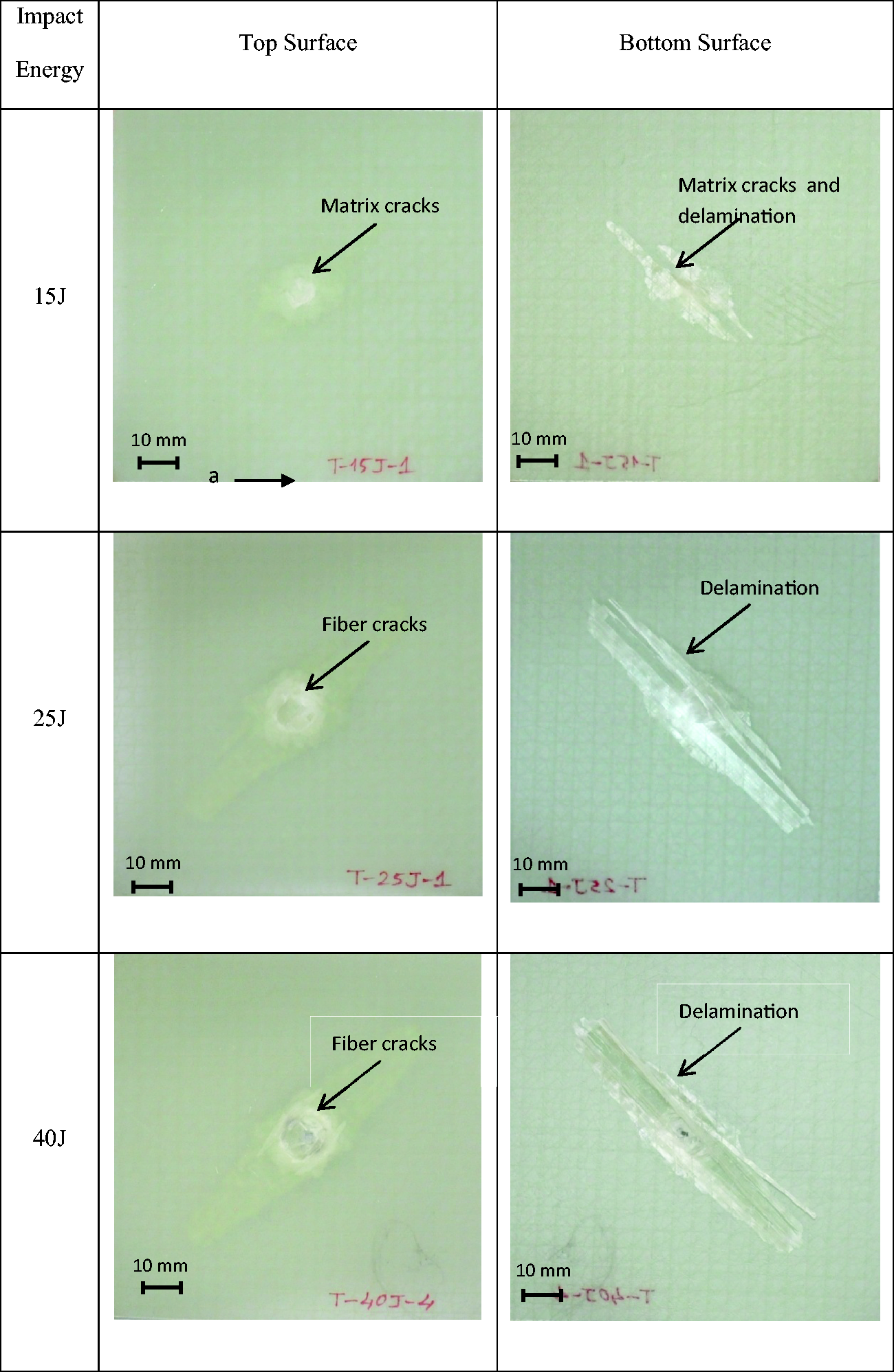
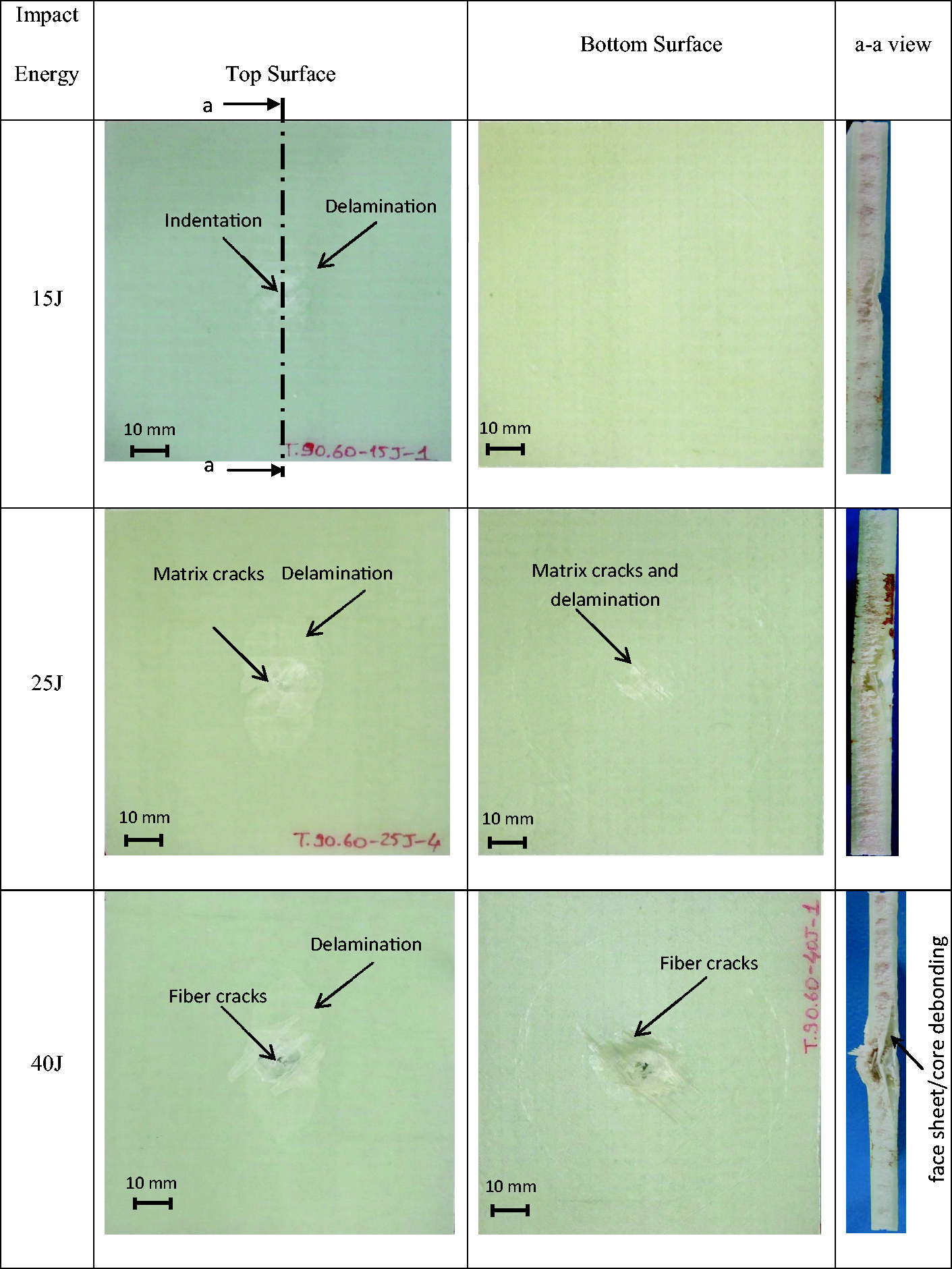
To evaluate the main damage mode of specimens having 5 mm, 10 mm, and 15-mm core thicknesses for two core materials, the images of the top and bottom surfaces and cross-sectional areas of specimens (at impact energies as 15 J, 25 J, and 40 J) are shown in Figures 9 to 14, and the images of the top and bottom surfaces of specimens without core material are shown in Figure 15. Figure 9 shows the impact-induced damage of the specimens with PET foam core having 5-mm core thickness according to impact energy. At the impact energy of 15 J, there is no damage seen at the bottom face sheet. And, indentation failure, matrix cracks can be seen at the top face sheet, and delamination occurs at the bottom interface of top face sheet. As the impact energy increases to 25 J, matrix cracks and delamination in bottom interface occur at the top face sheet, and matrix cracks were seen at the bottom face sheet. In the photos of the damage specimens under impact energy of 40 J, fiber cracks were observed at the bottom face sheet. Debonding occurred between top face sheet and core. Also, delamination areas increase at the top face sheet by increasing the impact energy. When the core thickness increases to 10 mm and 15 mm (Figures 10 and 11), delamination in bottom interface and fiber cracks were observed at the bottom face sheet at impact energy of 40 J. In the other impact energies, the main damage of specimens having 10 mm and 15-mm core thicknesses is almost the same with the specimens having 5-mm core thickness. Face sheet/core debonding was increased compared to specimen with 5-mm core thickness at same impact energy because of the higher bending stiffness.
Damages of specimens with [ ± 45°/0°/90°/PET/90°/0°/ ± 45°] having 10-mm core thickness. Damages of specimens with [ ± 45°/0°/90°/PET/90°/0°/ ± 45°] having 15-mm core thickness. Damages of specimens with [ ± 45°/0°/90°/PET/90°/0°/ ± 45°] having 15-mm core thickness. Damages of Damages of specimens with [ ± 45°/0°/90°/PET/90°/0°/ ± 45°] having 5-mm core thickness.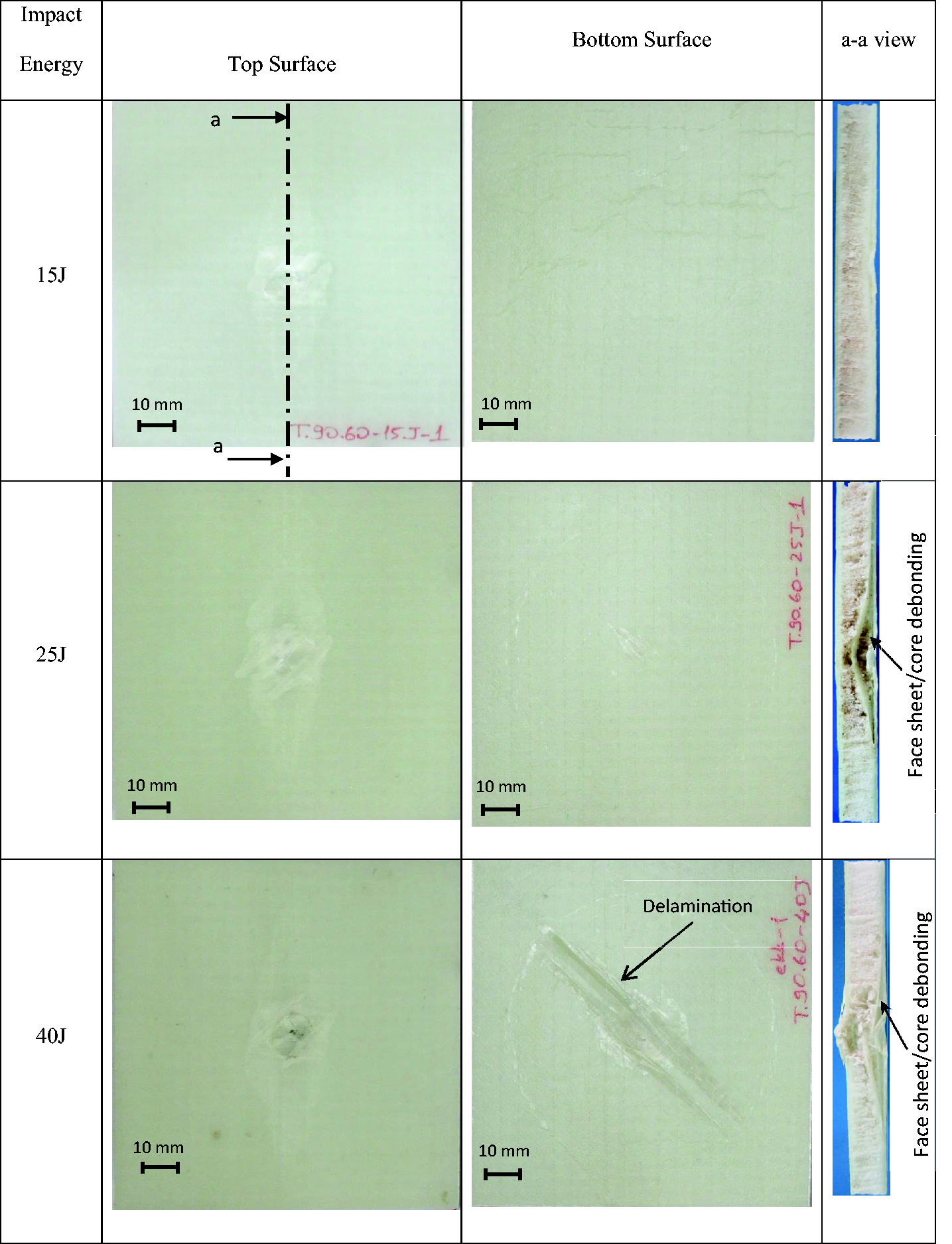
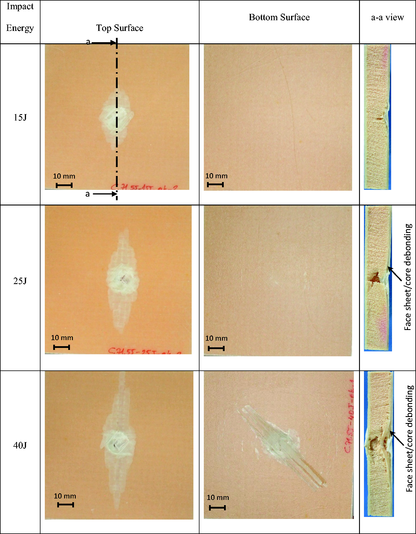
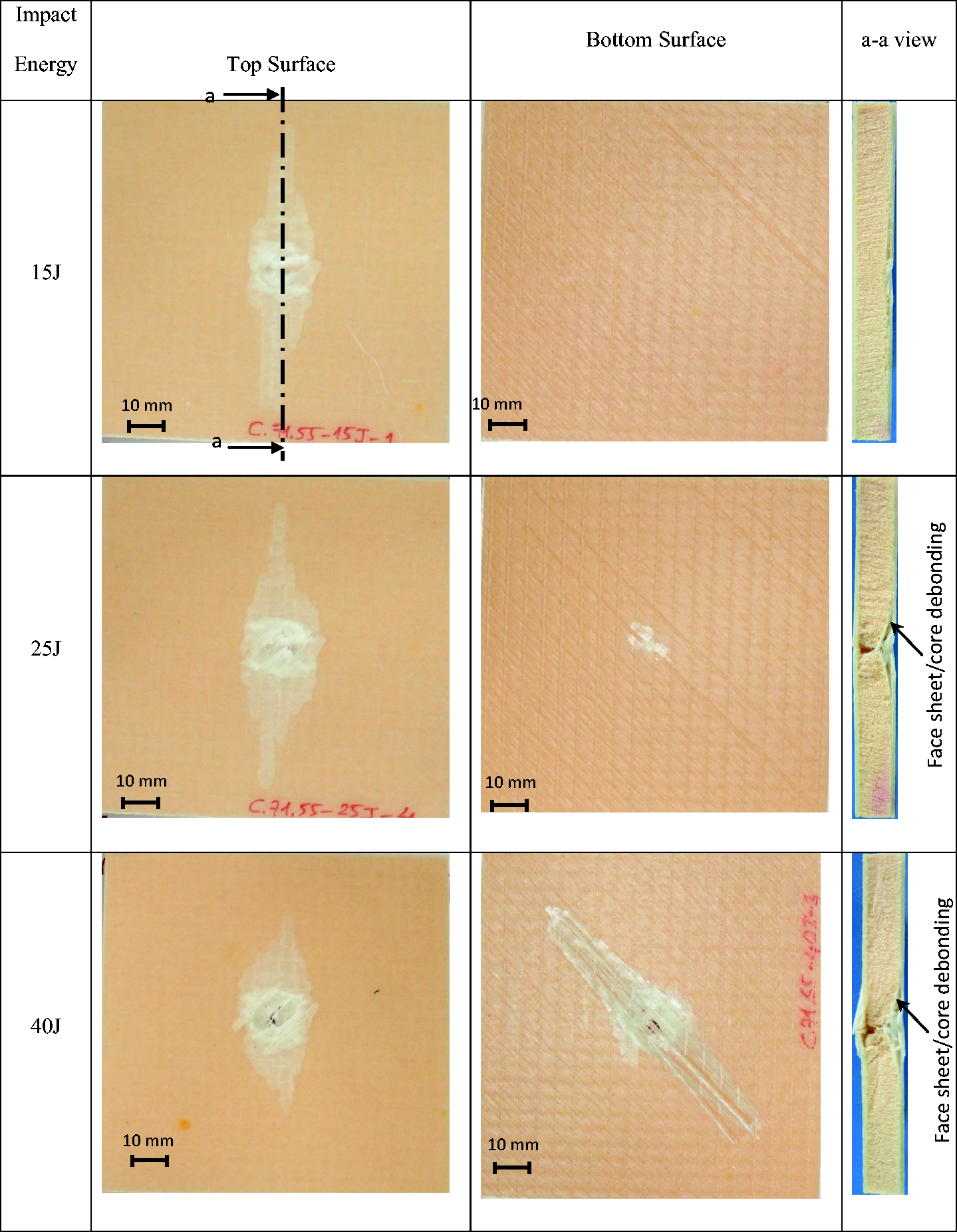
For other core material and thicknesses, impact-induced damage is nearly same with the specimens with PET foam core (Figures 12 and 13). Only, there is no damage seen at the bottom face sheet of specimens with PVC foam core having 15-mm core thickness under impact energy of 25 J (Figure 14), while it is seen in the other specimens of same thickness and impact energy.
Damages of specimens with [ ± 45°/0°/90°/PET/90°/0°/ ± 45°] having 5-mm core thickness. Damages of specimens with [ ± 45°/0°/90°/PET/90°/0°/ ± 45°] having 10-mm core thickness.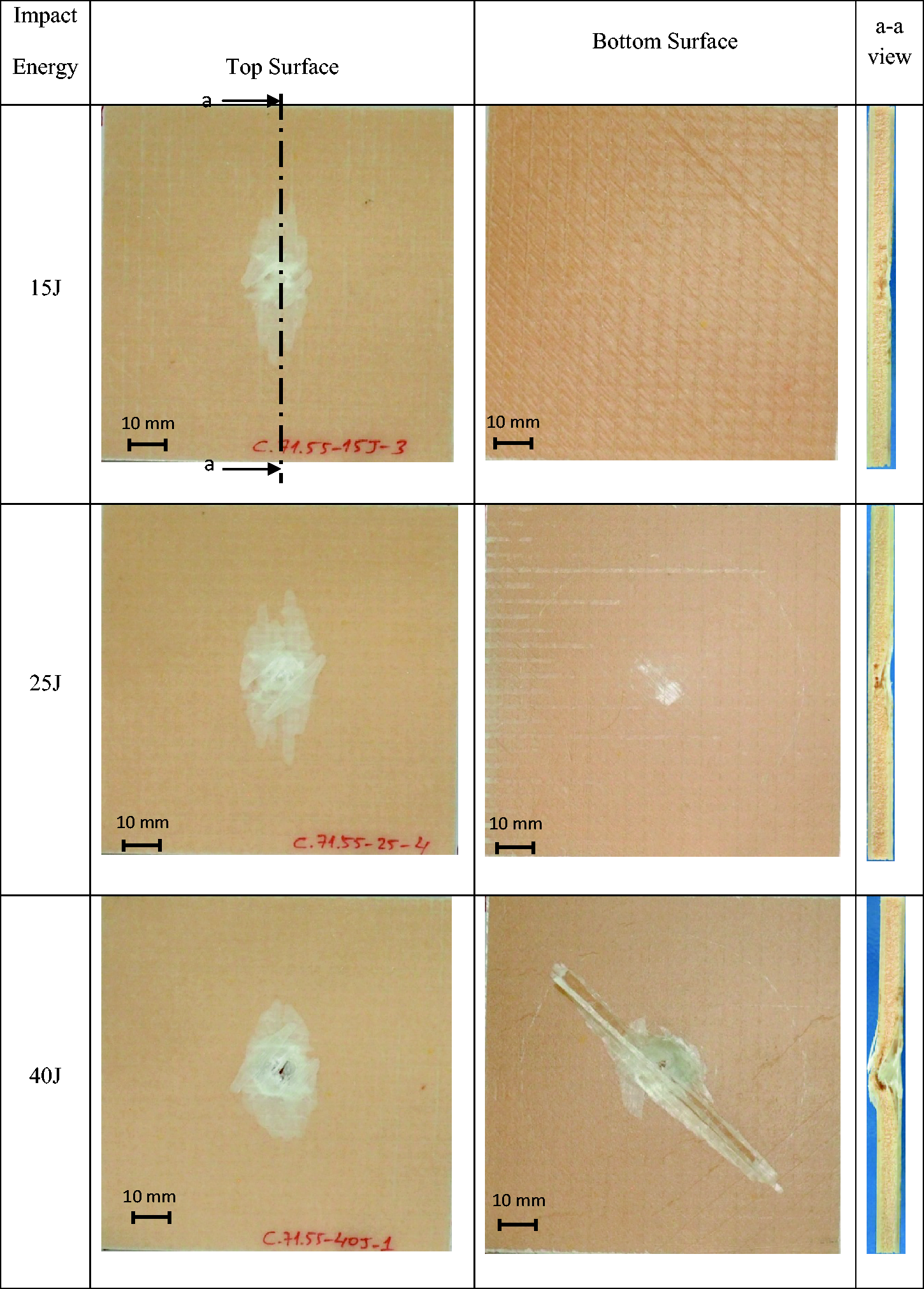
In Figure 15, photos of specimens without core impacted at 15 J, 25 J, and 40 J are given. Matrix cracks and delamination were seen under impact energy of 15 J. As the impact energy is increased to 25 J, delamination was observed at the bottom interface. In the 40-J impact energy level, delaminations in bottom interface and fiber cracks were observed, and impactor passes through the thickness.
Conclusions
In the present study, the effects of PVC and PET foam core materials and their thicknesses on low-velocity impact behavior of sandwich composites are investigated experimentally. Sandwich composites were fabricated by VARIM with [ ± 45°/0°/90°/core/90°/0°/ ± 45°] orientations. Impact characteristics like maximum contact force, time, deflection, and absorbed energy were obtained and compared for each core material and thickness and The contact force versus deflection and time curves of having 5-mm core thickness specimen consist of one peak and show nearly the same impact characteristics with laminated composite plates. Because, contact time is very small to deform core with small thickness. So, core with small thickness has no effect significantly on contact force and rigidity of specimen, with small core thickness is higher than the thicker ones. Therefore, it behaves as a laminated composite. As the core thickness increases, specimens show more elastic behavior, and so, maximum contact force value decreases while contact time and maximum deflection values increase. Also, in the thicker core thicknesses, the specimens absorbed more energy. Therefore, penetration portion that sees in the wide energy ranges. The loading portions of the curves are nearly same for all core thickness. But, unloading portions are different because of the different damage mechanism. According to impact energy levels, impactor causes damage in the bottom face sheet or stops in the core material. So, the differences are observed in the unloading portion of the curves. The bending stiffness of the specimen without core material is higher than all the specimens with cores. Bending stiffness is the maximum at the specimen with PVC and the minimum at the specimen with PET foam cores. This property is compatible with the compressive modulus of the core materials. For each type of core materials and their thicknesses, impact damage area increases by increasing the impact energy. Because, as the impact energy is increased, the specimens absorbed more energy that increases the impact damage area. In the small energy levels, the matrix damages, small fiber cracks, and face sheet/core debonding occurs, while these damages were seen clearly in the higher impact energy levels.